Electric circuit angular grinders. How to make the grumbling frequency regulator with their own hands. Roll control and smooth start - for what you need
Corner grinding machines (USM), called grinders, are in demand and reliable tool. But everything is once breaking. Perform the repair of the grinder with their own hands is easy if you are in front of you telling step-by-step order Performance of the repair of the USM. Below you will find answers to any questions about the repair of gearbox, rotor, stator, coal brushes of corner car.
Corporal machines in the midst of home masters are extremely popular. The possibility of replacing the working bodies allows to produce cutting, grinding, polishing operations.
The presence of a smooth starter makes the tool work safe and convenient. Repair of the angular grinding machine is simple and can be performed independently. For those who decide to implement repair USM On your own, you will need a circuit of a coal-glare machine of the desired type, tool, lubricants and this instruction.
Any repair of the grinder begins with the study of faults. The brander is sufficient. The rotating rotor across the rowing gear transmits torque to the shaft (spindle) of the working body. The desired working tool is installed on the spindle, whether it is cut stone, grinding or polishing circle and the necessary technological operation is performed.
By the way, about the shape of the tooth. On the low-power grotes are installed straight gears. The osostic gears are used in grinders with a power of more than 1000 W.
Corner-glasses, like any tool break out over time. Causes of Bulgarian faults can be different. They appear not only from improper operation of the tool, but also a late replacement of coal brushes, lubricants.
In independence, from the model of the angular grinding machine, everyone appears in the same nodes. Faults of Bulgarians are conditionally divided into and electric. For beginners, fault repairmen are divided into simple and complex.
Mechanical malfunctions of the USM
Bulgarian is a corner-glare machine designed to perform cutting, grinding, polishing work. Bulgarian in the process of work is exposed to large loads, works in a dusty environment.
Excessive loads When using a grinder in the "cutting mode" cause elevated wear not only the bearing, but also the gear gear teeth.
The main malfunction of the grinder on the mechanical part, wear or destruction of the sliding bearing on the shaft of a large gear of gear gears.
Eliminate the brandlock malfunctions is easy if there is its scheme, a description and recommendations for execution at hand. repair work.
Repair of bearings sliding
The weak point of any angular grinding machine are bearings. And although they are a bit in the design, only three, they are most often leading to mechanical breakdowns. For bearings, negative impacts are provided:
- high speed of rotation;
- work on limit modes;
- insufficient lubrication;
- dipping dust or dirt;
- fine replacement or destruction of coal brushes.
The design of all the grinder provides quick and not constituting complexity to replace any bearing.
Faults of the grinder associated with the wear or destruction of the sliding bearing on the gear shaft are characterized by the appearance of unpleasant outsiders.
The destruction of the sliding bearing is detected by the lathe check of the working tool setting. Determined by swinging in different directions of the shaft when installing a working tool.
If you install the working tool, check the set of the shaft, sharing for its end in different directions. The backlash should be absent or be minimal.
The appearance of the backlash indicates the need to replace the sliding bearing.

Bearing repair is to remove it from the case and removal from the gearbox.
Remove the bearing from the shaft is better using the puller. The inner clip of the destroyed bearing is best to get through the tap the desired diameterpreviously screwed into the clip.

With the rotor, bearings are removed using a puller or a people.
In vice, keys or metal stripes are inserted, the bearings are stacked on the keys and using a soft metal copper and a hammer weighing at least 400 g are dyed from the shaft axis.

Repair of the Reducer Bulgarian
The degree of wear of the gear gear of the grinder is checked on the contact stain. The reducer is completely cleaned from the old lubricant. A special blue gear is applied to the small gearbox, the gearbox turns. Next, you need to remove the larger cososophy gear and look through the magnifying glass on the contact stain. It should take a total of at least 50% of the surface of the tooth.

Otherwise, the gears must be replaced or adjusted to the tooth profile. Not once was described on the pages of this site.
But such a malfunction is eliminated only by an experienced master. Exactly shaky, cut or destroyed gears are changed entirely, and in a pair.
How to disassemble the grinder gearbox
When repairing the gearbox, any grinder is the most difficult task is to remove the gear and reassessing the support bearing.
The disassembly of the gearbox begins with removing the gearbox cover Pos 1 and disconnect the body of the stator and the release of the rotor pos.2. The released rotor is clamped in vice and unscrew the fastening nut pose.3 leading small gear.

The spindle bearing is pressed in the gear cap. To get the bearing, in some grinders should be removed the locking ring fixing the reference bearing, and remove the bearing.

Destroyed bearing pos 1 in the gearbox case pos.2 is easiest to get it, going with a screwdriver.
In other models, the gear in the spindle fixes the retaining ring.

The led large gear on the spindle is attached in several ways:
- The gear is painted on the spindle.
- The gear is mounted with a key.
The leading small gear either on the shaft is winding along the left thread (in some models of asparactions, thread the right), or fixed with a key connected and clamping a nut.

How to shoot gear gear
In the grinders up to 1000 watts, sprinkled gears are used, and the gears are used in the corner-glasses.
The repair of the gear is to replace them, and only in a pair.
Long and uninterrupted operation of the gearbox depends on availability.
Spindle fixing buttons repair
The spindle fixation button is designed to quickly remove the working tool. The cabin breaks down when the disk is pressed at the time. The repair of the grinder is to fully replace the button.
The button should be pressed only in the state of the full brand stop.
Electric malfunctions Bulgarian
The electrical circuit of the main part of the Bulgarians is almost the same. The rotor transmits the rotational moment through the reducer to the working tool. The rotor rotates in the stator field. Control chains consist of a button controlling turnover and carrying out smooth start Tools, coal brushes to transmit alternating voltage to the collector lamella. Power on the tool is fed through the connecting cable.
The main faults of the Bulgarian on the electrical part include:
- breaking cable at the entrance to the tool;
- destruction or wear of coal brushes;
- failure of the power button;
- breakdown or short circuit of the stator;
- break or short circuit of the rotor;
- clearance or generating collector lamellamas.
Bulgarian malfunctions on the electrical part are best determined by a tester or other device. Suitable for these conquer and self-made device called people "Arkashka" .
The grinding scheme is quite simple and does not require special knowledge. It is only necessary to abide care and safety equipment when performing repair work and know electrical engineering in the amount of high school.

Finding the break wire
One of the common breakdowns of the grinder becomes the impossibility of turning on the tool or spontaneous stop during operation. The cause of malfunctions of this kind is becoming a failure of the power cable pos.27 at the entrance site. A malfunction is eliminated by the replacement of the cable or the disposal of the failed area. The malfunction is easily located with the tester.
If there is no tester at hand, but there is a screwdriver with an neon indicator light, then the malfunction can be found, alternately connected power wires to the phase.
Faults of coal brushes
The reliable operation of any power tool to a large extent depends on the integrity and proper operation of coal brushes. High-quality adjacent coal brushes, their correct location Regarding the collector lamellae affects the efficiency of the rotor collector.
Remember! The length of the coal electric power can not be less than 8 mm.
Timely replacement of coal brushes avoids most of the faults.
The degree of wear of coal brushes is characterized by types of sparking at the reservoir. The sparking should be uniform throughout the spnow of the contact of the coal brush and the lamellae and not exceed the lengths of more than 8 mm. Circular sparking indicates the appearance of a malfunction in the rotor chains.

Repair the power on and regulator
Malfunctions The power button is most often manifested in the difficult and unreliable turning on the tool when starting. Such a malfunction spontaneously appears and disappears.
It is unacceptable to work with a grinder with a faulty power button. This malfunction leads to the encoffin of cutting disks during operation and their destruction with unpredictable consequences.
The fault is eliminated by the full replacement of the button to the new one.
IN modern models Bulgarians built-in a smooth starter device with revolutions. It is not subject to repair, but will require a complete replacement. No, advanced master-leafers, of course, will be able to fix such a node.

Repair of stator
The spontaneous promotion of the machine shaft specifies on the failure of the stator, the Bulgarian begins to type the maximum turnover. Such a fault indicates the emergence of an inter-touch closure in the stator winding.

Some malfunctions can only eliminate specialists. The extension of the uninterrupted operation of the stator can only be timely cleaning, lubrication and replacement of coal brushes and bearings.
Usually the stator fails quite rarely. This brings frequent overheating tool when working. The fault is manifested by a strong heating of the body of the grinder and the appearance of the smell of burner isolation.
In the stator can be like a breakdown and short circuit. Without viewing the stator, the malfunction data is easy to find using the IR-32 instrument.
Faults are eliminated by the replacement of the stator. For lovers to make your own hands we can recommend. There is nothing difficult in this.
The stator is easily removed, but in different models Esch in his own way.
The procedure for removing the stator:
- remove the grinders;
- remove the rotor, after removing the fixture bar;
- remove the plastic protection of the stator;
- unscrew the stator mounting screws in the case;
- remove the handle cover and disconnect the power wires to the Stator;
- remove the stator by tapping on the case wooden hammer or bar.
Repair of the Rotor USM.
The failure of the rotor in the Bulgarian is caused by the incorrect operation of the tool, frequent overheats, late replacement of coal brushes, hitting the collector lamellas of abrasive particles and dust.
Initially, the length of the sparks on the collector increases, then the smell of Gary appears and, at the last stage, smoke. The work of the defective gearbox is accompanied by a knock and a hum.
Destruction Even a pair of teeth leads to the wrong operation tool.
Extend the life of the rotor can be prevented from entering the dust tool, preventing the tool overheating, timely change of coal brushes and lubricants, using only those working tools and such a diameter that the manufacturer of the power tool recommends.
The rotor is a complex node that requires repair in service centers. But lovers can make their own hands.
Repair collector and Rotor Lamella
Disassembly of the rotor does not represent a special complexity.
The procedure for extracting the rotor from the angular grinding machine:
- remove the handle cover of the grinders;
- free and remove coal brushes;
- unlock the screws fastening the gear housing to the main case;
- remove the gearbox;
- remove the rotor.
The removed rotor must be carefully examined. If large grooves are grazed on the lamellae, it should be deleted, the passing collector in the lathe.
With minor grooves, the defect is eliminated by grinding. The rotor is clamped into the cartridge of the electric drill and using the appliance and grinding paper is removed. The process is simple.
The drill is clamped in vice or securely attached on a flat surface. In the cartridge, the drill inserts that end of the rotor on which the lamellas is placed, and it is secure. Bearings have previously removed from the rotor.
The second end of the rotor must be pushed by a set of wooden bars. The drill is turned on and a small number of revolutions is exposed. At the first stage, use grinding paper of large grain №40..80, at the final stage smaller №120..200.
After grinding, you need to promote the grooves between the slats. It is best to perform his bladespecially sharpened. After milling the grooves of the collector, the edges of the lamella must be cleaned of burrs, with the help of a diamond noodhyle. Correct slaughtels should not have burrs.
Press the class
Tell VK
Corner grinder Mastermax MCP - 2800
Device corner grinding

The angular grinder in our household use is the necessary power tool. Depending on the establishment of one or another nozzle to the grinders, it is possible to perform a varied amount of work.
In its appearance and design, similar grinders are the so-called grinders consisting of such parts as:
- protective casing;
- ventilation hole;
- push-button switch;
- side handle;
- spindle lock.
The photograph shows the engagement mechanism or in other words - the pairing of the mechanical part of the gearbox with the electric motor.

Reducer and electric motor grinders
For the mechanical part, depreciation is subject to:
- bearings;
- gear gears.
It would believed that give a complete explanation for the mechanical part of the gearbox, it simply does not make sense.
Nozzles to corner grinders have a different range, depending well on the work carried out.


Electrical circuit - corner grinding
We concentrate our attention \\ Fig.2 \\ in the following schematic image, - the principle of operation of the electric motor.
The image of the red arrow in the figure shows the direction of the current, - as it is customary in the section on electrical engineering: "The current in the electrical circuit proceeds from the source \\ clamp \\ with a positive potential to a source with a negative potential. Moreover, the positive potential changes its sign to the opposite - from resistance having a connection in an electrical circuit.
The electrical circuit here closes on the collector, or rather on the contact connections "Winding - collector" \\ for the rotor of the electric motor \\.
That is, the rotor collector through graphite brushes in the scheme - has electrical connection.
The two windings of the electric motor stator are connected in the electrical circuit sequentially.
In his practice, such an electrical connection \\ Fig.2 \\ for all elements of the collector electric motor - I have not met that the wire with one potential has a direct electrical connection with a collector through a graphite brush, and the second wire with another potential had a serial connection through two stator windings. with a second graphite brush.
The most simple and complete explanation of these electrical connections, the electrical circuit of the collector electric motor \\ Fig.3 \\ is directly itself. It is such a compound of all elements typically for grinders engines, where the electrical circuit closes on two rotor windings - in this way.

Motor winding connection
Here we can see that the two windings of the rotor of the electric motor for this site are interconnected between themselves and have a contact electrical connection "collector - brush".
Connection two rotor windings Regarding the external source of alternating voltage - parallel.
From among the causes of motors of the electric motor of the grinders, it is possible to bring such a malfunction as the wear of graphite brushes in contact friction with the electric motor collector.

This detail is both among other other parts for power tools - you can purchase specialized technical departments.
Diagnosis of electric motor — Shlifmashins
The diagnosis of the electric motor of the grinders \\ Fig.3 \\ should be carried out for individual sections of the electrical circuit of this circuit.
To do this, you will need either the device Oncemmeter or the device multimeter. The device multimeter is pre-measured to measure the resistance - is set to the appropriate position.
To measure the resistance of two separate stator windings, one appliance probe is connected to the brush contact, the other appliance probe is connected to the appropriate pin of the electric fork.
When breaking this section, the device will respectively indicate the absence of resistance.
If working, the device will indicate the resistance of a measured area of \u200b\u200bthe electrical circuit.
The connection of two devices of the device to two pins of the electric fork of grinders, - the instrument display will show general resistance for:
- two stator windings;
- two rotor windings,
- That is, it will indicate the total resistance value.
Changing the speed of rotation of the rotor of the electric motor \\ Fig.4 \\ is carried out through the next electrical circuit.
The electrical circuit consists of:
- resistor R1 \\ 0.5 W \\;
- resistor R2;
- resistor R3 \\ 5 W \\;
- diode VD1;
- triode thyristor VS1.
The R2 resistor performs the potentiometer function, at the expense of which the current changes in the load. Load in this explanation, is an electric motor.
Thyristor triode - creates locking current for the opposite direction. Management is carried out through the cathode.
Well, we sorted out in simple electrical circuits. It remains to make your decision in cases of malfunction, - to give the electric motor to repair or fix it yourself.
Turning to be admitted to the repair workshop household appliances- You can already set out the reason for the malfunction of your power tool.
That seems to be all.
Almost every wizard, often working with the metal, knows the device of the electric diagram of the grinder. Bulgarian is a tool that is most commonly used for cutting metal. This tool is a source of increased danger, so before each use it is used to check the health and mechanical components of the structure.
The corner grinding, which in the post-Soviet territory wears the name "Bulgarian" was another 3-4 decades ago the dream of every homemade craftsman. 30-40 years ago This work tool was produced by one manufacturer, the factory "Eltos-Bulgarket", located on the territory of Bulgaria in the city of Plovdiv. Currently, manufacturers offer consumers various models and modifications of this tool, but the main design nodes have practically not changed. Most structural elements on various models And the modifications differ only with sizes.
Electrical component of the structures
For the entire period of its existence, the appearance of the instrument has practically remained unchanged. Bulgarian has an oblong case in which the electric drive and gearbox is mounted. On the side of the tool, a handle for holding the tool in the operating position is fixed, additionally, a protective cover covers the working element is fixed to protect the wizard on the tool housing.

Bulgarian, like any tool, during operation may fail. In most cases to eliminate breakdowns required the simplest renovation Working equipment, its electrical component.
In order to repair, you need to know the device not only the mechanical part, but also to the power supply tool. For high-quality repair, the principle of work of the Bulgarian should be studied. The composition of the electrical circuit of the grinder includes the following structural elements:
- anchor;
- collector;
- electrolars;
- gearbox;
- stator;
- start and lock button;
- power cable with a fork for connecting to the household network.
Each of the components is designed to perform certain functions in electrocups, and the malfunction of any of them leads to stopping the functioning of the device. For example, anchor is a rotating element of electrocups. It provides the transmission of the rotational movement to the grinding disk. In order for the tool to function efficiently, the anchor should rotate at high speed. The higher the speed of rotation of this structural element, the higher the power of the device.
Functions performed by the Bulgarian design components

The collector is an anchor platform to which all power and control cables are derived. The collector's task is to conduct passing signals to the engine and the control unit. The collector when removing the cover of the housing is immediately striking the presence of polished plates that have large sizes.
Electrokers in the design of the device are used to transfer the electric flow to the collector from power cable. In the process of work, if the brushes have a normal technical condition, then through the ventilation holes of the case, a smooth glow is seen. If the glow in the process of inclusion of the device is not observed or has a pulsating character, this is a sign of the emergence of problems with this electrical component of the device.
Reducer is one of of the most important components Designs. Its appointment to transmit rotation energy from the rotating anchor to the grinding disk, providing its rotational movement. The gearbox is responsible for the frequency and power of rotation of the working tool of the grinder.
The stator is a complicated appliance assembly unit. The design of the stator includes windings that, when interacting, through a magnetic field with anchor windings, lead the latter in motion. Stator coils have a certain number turns calculated in accordance with the requirements of electrical engineering. At the exit of this node, the rewind of coils is required. This operation requires certain knowledge and skills. The rewind of the stator is better to trust a workshop specialist.
Electroscheme device Bulgarian

In the process of repairing, it is not enough to know enough to the purpose of the main structural elements of the tool electrical circuits, you need to be able to read it. Electroshem Bulgarian is not very complex. However, even such a design in some cases during repair can cause difficulties.
The electric hammer is arranged in a certain way. Two stator coils are connected in series through the cable to the household network with a voltage of 220 V. These coils are electrically between themselves are not connected. The inclusion and shutdown of these windings is carried out mechanically by switching. This switch is mechanically associated with the start button. Each of these windings through the contact of the switch binds to the corresponding graphite brush.
Then the electrical panel with the help of two parallel windings connected to graphite brushes goes to the rotor coil. The chain closes on the collector terminals. The anchor winding includes a large number of Separate small windings, but only two are connected to brushes from graphite.
Most often, the grinder fails because of the breakdown of its electrical components and the breaking of electrocups.
For the diagnosis and detection of faults in electrocups, a special design is used - a multimeter. This device may be required not only to test the working capacity of the grinder, but also any other electrical tool or instrument.
It is more convenient to start diagnosing from the electrotock input site. The check is carried out in stages, checking and nickning each of the elements of the device's electrical circuits.
Small repair of Bulgarian

In case, after pressing the start button, the tool does not start, it is likely that the cause of the breakage is a small malfunction that can be eliminated own forces. The diagnosis is best carried out on the principle of simple to complex. Most often, the place of rupture in electrocups is a plot from the source of power supply to graphite brushes. During the repair process, remove the casing and test the circuit on the power flow area to the pad button. If there is no current supply to the button terminals, the feed electrocabel should be replaced.
If the electrotoks enters the start button, but not transported further, then the failover of the instrument is to output the start button. In case of failure, the buttons should be replaced. For this purpose, you should carefully disassemble the starting mechanism and replace the start button. When connected, you should pay special attention to the terminals, since the wrong connection may result in the winding of the tool windings.
Replacing graphite brushes
The failure of graphite brushes is one of the most common broken breakdowns.
The service life of this element of the tool design is about 1.5-2 years. The process of replacing brushes does not represent special difficulties. To replace these structural elements, you will need to open the tool housing. After opening the housing using a screwdriver, the brush holders that are fixed on the collector are shifted.
The replacement of brushes should be made only on the branded purchased in special stores. When purchasing a new brush, it should be compared with the original, which is extracted from the tool. The new brush must be completely, in all respects, coincide with the leakage extracted from the grinder. After installing new brushes, you should check the smoothness of its movement.
After installing and checking the smoothness of the brush movement, it is fixed using the brush holder. After fixing the brush holder, the tool body closes.
I gave me a friend to solar * Balgarka *, says: they did it work before, and now it does not work. I understand the machine itself, I understand that the cutting disk is attached perpendicular to the engine rotor (dangerous thing). So when I disassembled it, I found it that I was trying to repair it to me. Inside everything on the twists was additives Cut. I need a scheme for connecting this Baida (drawing or sketch) to clearly. The machine includes: stator, rotor (two brushes), condenser with three outputs and the power button. Help please figure out, and then some kind of hat comes out, I took the device and did not.Replacing the brushes is the only operation that in the process of repair should be carried out on its own, the rest of the repair is better to entrust to those skilled in the art.
Connection diagram * Bulgarian * If without smooth inclusion, that's the whole scheme. May break the switch only one wire.
The condenser is obsessed with extreme conclusions on the entrance after the button, the average to the iron stator.
Attached images
Connection diagram * Bulgarian * aha. I understand the engine is connected sequentially. And what does a scheme look like with a smooth start? It would be interesting to see.
Connection diagram * Bulgarian *
Connection diagram * Bulgarian *
or is this connection more complicated and requires additional parts?
Yes required additional details And not in every grinder they can accommodate.
Page 2
Electric motors. PLATES. Connection schemes.
- Mark this forum read
| Sayan author, 20 Sep 2009 |
| |||
| Author NUB, 22 Jun 2008 |
| |||
| Author BIM, 29 Jan 2008 |
| |||
| Author BIM, 26 Oct 2011 |
| |||
| Author NUB, 24 Apr 2008 |
| |||
| Author SEMKO, 18 Jan 2018 |
| |||
| Author ORIO55, 12 Mar 2017 |
| |||
| Author Nikomas, today, 04:16 |
| |||
| The author of Kotelev, 19 Mar 2015 | ||||
| By Pavel47, 19 Jan 2018 |
| |||
| By Lekalschik, 22 Apr 2013 |
| |||
| By Treugolnik, 13 Jan 2008 |
| |||
| By Aftaev, 14 Feb 2010 |
| |||
| Author Sergeyil, 22 Oct 2014 |
| |||
| Author Timur05, today, 12:22 |
| |||
| Author Ivanivanov76, 20 Jan 2018 |
| |||
| Author DOCR, 02 SEP 2012 |
| |||
| Author former, yesterday, 16:44 | ||||
| Author DX1, 07 Jan 2018 |
| |||
| Author Petrk, 05 Dec 2016 |
| |||
| Valen author, 12 Feb 2012 |
| |||
| By wagner_poma, 26 jul 2013 |
| |||
| Author N-S-IV, 25 May 2017 |
| |||
| Author Duke_Nuke, 24 Dec 2017 |
| |||
| Author Aleksandr16rus, 20 Jan 2018 | ||||
| Author ArchStyle, 26 Dec 2017 |
| |||
| The author IMPartial, 30 Sep 2016 |
| |||
| Author Killdozer, 15 Jan 2018 |
| |||
| Author Trefoil, 14 Jan 2018 |
| |||
| Author Dr_LAW, 18 May 2010 |
|
- You can not create a new topic
www.chipmaker.ru.
Repair corner grinders - do it yourself
Corner grinder Mastermax MCP - 2800
Device corner grinding
The angular grinder in our household use is the necessary power tool. Depending on the establishment of one or another nozzle to the grinders, it is possible to perform a varied amount of work.
In its appearance and design, similar grinders are the so-called grinders consisting of such parts as:
- protective casing;
- ventilation hole;
- push-button switch;
- side handle;
- spindle lock.
The photograph shows the engagement mechanism or in other words - the pairing of the mechanical part of the gearbox with the electric motor.
Reducer and electric motor grinders
For the mechanical part, depreciation is subject to:
- bearings;
- gear gears.
It would believed that give a complete explanation for the mechanical part of the gearbox, it simply does not make sense.
Nozzles to corner grinders have a different range, depending well on the work carried out.

Electrical circuit - corner grinding
We concentrate our attention \\ Fig.2 \\ in the following schematic image, - the principle of operation of the electric motor.

The image of the red arrow in the figure shows the direction of the current, - as it is customary in the section on electrical engineering: "The current in the electrical circuit proceeds from the source \\ clamp \\ with a positive potential to a source with a negative potential. Moreover, the positive potential changes its sign to the opposite - from resistance having a connection in an electrical circuit.
The electrical circuit here closes on the collector, or rather on the contact connections "Winding - collector" \\ for the rotor of the electric motor \\.
That is, a rotor collector through graphite brushes in the diagram - has an electrical connection.
The two windings of the electric motor stator are connected in the electrical circuit sequentially.
In his practice, such an electrical connection \\ Fig.2 \\ for all elements of the collector electric motor - I have not met that the wire with one potential has a direct electrical connection with a collector through a graphite brush, and the second wire with another potential had a serial connection through two stator windings. with a second graphite brush.
The most simple and complete explanation of these electrical connections, the electrical circuit of the collector electric motor \\ Fig.3 \\ is directly itself. It is such a compound of all elements typically for grinders engines, where the electrical circuit closes on two rotor windings - in this way.
Motor winding connection
Here we can see that the two windings of the rotor of the electric motor for this site are interconnected between themselves and have a contact electrical connection "collector - brush".
The connection of two rotor windings relative to the external source of alternating voltage is parallel.
From among the causes of motors of the electric motor of the grinders, it is possible to bring such a malfunction as the wear of graphite brushes in contact friction with the electric motor collector.

This detail is both among other other parts for power tools - you can purchase specialized technical departments.
Diagnostics of the electric motor - grinders
The diagnosis of the electric motor of the grinders \\ Fig.3 \\ should be carried out for individual sections of the electrical circuit of this circuit.
To do this, you will need either the device Oncemmeter or the device multimeter. The device multimeter is pre-measured to measure the resistance - is set to the appropriate position.
To measure the resistance of two separate stator windings, one appliance probe is connected to the brush contact, the other appliance probe is connected to the appropriate pin of the electric fork.
When breaking this section, the device will respectively indicate the absence of resistance.
If working, the device will indicate the resistance of a measured area of \u200b\u200bthe electrical circuit.
The connection of two devices of the device to two pins of the electric fork of grinders, - the instrument display will show general resistance for:
- two stator windings;
- two rotor windings,
That is, it will indicate the total resistance value.
Changing the speed of rotation of the rotor of the electric motor \\ Fig.4 \\ is carried out through the next electrical circuit.
The electrical circuit consists of:
- resistor R1 \\ 0.5 W \\;
- resistor R2;
- resistor R3 \\ 5 W \\;
- diode VD1;
- triode thyristor VS1.
The R2 resistor performs the potentiometer function, at the expense of which the current changes in the load. Load in this explanation, is an electric motor.
Thyristor triode - creates locking current for the opposite direction. Management is carried out through the cathode.
Well, we sorted out in simple electrical circuits. It remains to make your decision in cases of malfunction, - to give the electric motor to repair or fix it yourself.
By contacting the workshop to repair household appliances, you can already set out the cause of the malfunction of your power tools.
That seems to be all.
zapiski-elektrika.ru.
Repair Bulgarian
Anchor is a rotating element of an electric motor containing windings. Sollector is an anchor, to which all windings are derived. It looks like a number of isolated plates from each other. The station is a fixed part of the electric motor containing windings. For coal parallelepipeds, bringing the current to the collector.
Reducer - a mechanical device for transmitting rotation with changes in power changes and speed.
The most popular tool in everywhere after a drill is a corner-glare or, as it is called more often, Bulgarian. Bulgarian is used for cutting metals, wood, concrete, grinding different surfaces, cutting of openings, doors, nose. If there is a Bulgarian, then the application can always be found and it happens especially when it ceases to function normally, jerks, twigs, the smell of Gary appear ...
Bulgarians are all arranged the same: the oblong case in which the engine and the gearbox is located, the knob and the protective cover is screwed on the side.

On the body of the grinder there is a sticker with source data. Here you can find both the personal number of the grinder and supply voltage - 230 V. Here is due to the maximum allowable voltage in the network. Current frequency in the network - 50 Hz. Current consumption - 5 A. Power consumed from the network - 1100 W, it turns out as a product between voltage multipliers (220 V) and current (5 A). The frequency of rotation of the disk installed on the Bulgarian - 2800-11000 rpm. Directly the anchor itself rotates with a greater speed than the disk. Specifically, this grinder is possible a stepped adjustment of the speed of rotation. The disc mounted on the Bulgarian has outside diameter 125 mm, the disk fastening nut has a thread M14.

The household tool calculated for phase voltage 220 V has an anchor winding and stator winding. Energy transmission from the network is performed using graphite brushes. The voltage from the network is fed to the switch that is mechanically connected to the turning on the grinder. The stator winding consists of two halves of electrically unlighted. An anchor winding consists of a variety of windings, but at any time the brush is associated with only two anchor windings.
When turning on the grinder, the current is fed to the input of half the stator winding, the output of the stator winding is associated with the brush holder in which the brush is inserted with the spring. The brush transfers the current on half the anchor winding, on the other hand, another brush gets current and through the brush holder transmits a current to another half of the stator winding. The current entered and left the Bulgarian. If the entire electrical circuit is good, then the anchor will start rotation.
Reverse, i.e. Changing the direction of rotation of the disk can be carried out if the wires are switched to brushes from stator windings. Just disconnect the wires on the brushes and change places.

In the end of the body of the Bulgarian, there is a red wheel for stepped adjustment of the speed of rotation of the anchor and the screw for removing the casing.

In this form, the grinders themselves are located inside the case and there are no access to them, but the developers simplified the replacement of brushes when removing the casing. After unscrewing the screw removed the plastic plate and the outer casing shifts towards the cord, exposing all the insides including the brush holders.

The speed control mechanism is electronic. The entire circuit is flooded with epoxy resin and the outside of the speed control and radiator are outward. What is hidden inside - the commercial secret of the company. When the block fails - the speed ceases to be adjusted, but remains at the maximum level. In any case, it is not necessary to despair, and in consistently with the grinder you can turn on the most ordinary dimmer - the light controller. With it, you can adjust the revolutions of any collector engine alternating currentThe main thing is that the engine power does not exceed the dimmer power.


On both sides of the housing there are steel brush holders with springs in the form of a curled steel strip. The spring is needed to hold the brush pressed to the anchor collector even with strong vibrations and heating the anchor itself.

The spring presses the brush and, as the brush, the spring brush is erased, everything lowers in the steel brush holder. Brushes are erased and decrease. When their length becomes insufficient Bulgarian ceases to work. IN expensive models Inside the brush is a spring, which repels the brush from the anchor collector. In cheap models, the brushes are not equipped with a built-in spring.

When choosing new brushes, it is better to contact the service centers specifically your producer of the grinder. The fact is that also as an artist on the schedule chooses twenty different simple pencils With different softness and producers of Bulgarians specifically develop brushes under a specific type of collector. If you use other brushes, for example, from the generator for a vase, then the anchor will most likely move soon, but at first, as a solution to the problem, such brushes will rise.

The grinding button is a plastic box with a mechanical lever transmission. The box is quite cumbersome to assume that it commutes large current currents and that the button goes not only in this equipment.

In the head part of the grinder there is a gearbox that increases the speed of rotation of the disk to 11000 rpm. The rod of the gearbox on which the disk dresses, contains a cut puck, which firmly sits on the shaft and has a supporting platform with a rubber ring for planting a disk.
Nearby is a foot with propuls, which fixes the protective casing. For greater safety, the protective shield can be shifted with subsequent fixation. The paw is pressed down to the grinder and shifted the shield to the desired level, after which the paw is released and it fixes the shield.

Nuts for fasteners of the disk are self-apparatus SDS and normal with turnkey holes.

Reducer keeps on four screws. If they are promoted and carefully draws up a screwdriver to open the cover, then the gearbox items will appear. The gear on the shaft of the anchor has left thread And with the help of the threaded, the anchor shaft is connected.
Rolling bearings are applied in the gearbox, i.e. Conventional sleeves are abundant with solidol. The teeth on the model with a capacity of 1,100 W - straight, apparently this is quite enough when plumbing works, but in the models of 1500 watts, gears with crystal teeth are used.


In order to remove the anchor gently remove the brushes, remove the gearbox and stretch anchor from the case for the gear. At the other end of the anchor, the rolling bearing will come close to the cord, which is recessed into the plastic case. To remove anchor you need to pull hard and carefully.
Anchor is a steel rod to which a steel cell typed from the plates is pressed. In the grooves of the cells, the cooles of the copper insulated wire. At the back end of an anchor, called the collector, all ends of the windings are derived. In the front end of the anchor there is a gear for transmitting rotation.

To win in the strength that you want to attach the disk to work use gear gear. For Bulgaris with a capacity of 2 kW, the anchor gear has 10 teeth, and the gear of the circle is 41 tooth. It turns out that at the speed of rotation of the circle 8000 rpm Anchor rotates 8000x41 / 10 \u003d 32800 rpm. If you consider that the number of collector contact plates 36, then 32800x36 / 60 \u003d 19680 Hz. This is approximately the frequency that gives interference to the network and to eliminate which ferrite rings are needed.

The drive gear is located on the shaft. At the production gear heated, and the shaft was cooled. After that, the gear was put on the shaft. The resulting connection is characterized cheap, simplicity and does not even make it possible to remove the gear without damaging the gearbox housing. Heat collected details It will cause the expansion of both the shaft and gears. The only thing to remove the gear is the puller. At the same time, the captures of the puller paw should be thin and strong to go into a small gap between the case and gear.


The shaft gear is attached to the thread. Probably, the manufacturers counted that the anchor gear is more often scattered than gear gear. On this model of the gear of the axle to increase the output power.

The gear has the right thread. For a surrounding gear, it is necessary to wind it with a rag in order not to break the teeth when unscrewed, clamp the gas key and turn counterclockwise.

After the gear is removed, it becomes clear that the thread is made not all over the height of the gear, but only on its small area. The plot without thread allows you to put on the gear exactly, without distortion.

| Fault | Elimination |
|
| Sparkling on the collector, smell, heating the case, the sound of cotton | Polluted collector | Disassemble, get anchor, clean the collector |
| Burned collector | Replace anchor |
|
| Bulgarian does not turn on | Worn brushes | Disassemble and replace both brushes |
| Slug button | Disassemble, replace the button |
|
| Faulty feeding cable | Make a breakdown seat and isolate |
|
| Mechanical sound when rotating disk | Worn gear | Disassemble, replace the gear, lubricate with cyatin (solidol, lithol) |
| The disc is constantly gaining momentum and Bulgarian goes into the separation | Vitkova closure of stator windings of the Bulgarian | Disassemble, replace windings (if it works) |
www.volt-220.com
Performance of the repair of the grinder with their own hands
Anyone, even the most reliable tool someday fails, and it happens, as a rule, at the most inopportune moment. Bulgarian repair with their own hands allows you to revive the tool with some small faults. In order to opening time spend necessary work, you need to know the design of the apparatus and have an idea of possible reasons His breakdowns. In most cases, the repair of the Bulgarian does not represent much difficulty and can be carried out by any person. Moreover, the tools of different firms differ little from each other, except that layout of parts and appearance.

Bulgarian device.
Tool device
Bulgarian or, more precisely, the angular grinding machine (USM) is based on the transformation of the torque of the electric motor in the rotation of the special disk, the axis of which is perpendicular to the axis of the engine. Depending on the type of disk, the tool allows you to cut or grind the blanks.
Schematic scheme The USM provides any tool consists of the following main parts: a durable case made of two half, with a handle for ease of operation (or without it); motor different power; electrical part; Reducer with safety clutch. The latter provides a reduction in the speed of rotation and the rotation of its axis by 90 °, and the safety clutch blocks excessive disk acceleration during disorders in the gearbox.
The basis of the gearbox is 2 conical type gears to change the direction of rotation. In devices with a capacity of up to 1.1 kW, the boosted gears on the engine anchor are most common, and with greater power - ososophy.
Bulgarian repair with their own hands allows you to revive the tool with some small faults.
When repairing the grinder with their own hands, it is necessary to initially proceed from two principles: hold an analysis of the circumstances preceding the output of the tool failure, which will help determine the cause, and repair the tool, moving from simple to complex. First you need to eliminate the simplest malfunctions, and then look for more complex breakdowns in a gearbox or electric motor.
The electric part of the grinder is considered the most capricious area of \u200b\u200bthe equipment. Its details can fail when the device is overloaded during operation, water or dust, from the occurrence of overvoltage in the network. In a mechanical system, bearings often become a weak link. The breakdown in this part is caused by a violation of the operating mode, in the gearbox of dirt and foreign objects, insufficient care of the tool (untimely and poor-quality lubrication).
Uninterrupted work of any good grinder depends on compliance the following conditions: Application apparatus only by its direct purpose, compliance with regulatory technical characteristics, excluding garbage from entering the housing and cleaning from dust, high-quality and timely lubrication of the mechanical part of the instrument, carrying out maintenance According to the applied instructions in full and within the specified time frame.
The basis of the electrical part is the AC motor by 220 V, consisting of a stator and the rotor. An important element is a collector through which the filing is carried out with the help of copper-graphite brushes. electric voltage on the rotor. The start of the electric motor is performed through the starting capacitor. To manage it, a special scheme and a starting mechanism in the form of a push-button switch are collected. Speed \u200b\u200bcontrol performs a mechanism for adjusting rotation revolutions.
Characteristic malfunctions and necessary tools
One of the most common faults is when you click on the Bulgarian start switch does not turn on. When repairing the grinder with their own hands, the following tools and devices will be required:
The diagram of the brine device from the inside.
- tester;
- ommeter;
- megommeter;
- a set of keys;
- screwdriver;
- a hammer;
- pliers;
- vice;
- tweezers;
- scissors;
- soldering iron;
- emery skin;
- tassel.
The first step in determining the cause of such a malfunction is a complete shutdown from the network and attempt to manually rotate the disk. If the disc is not going to rotate or scrolls very tight, then the reason is usually associated with the mechanical part. In the case when the disk rotates freely with hand, you can hope for the elementary reason that causes the non-electricity to the engine.
Attempt to repair the tool begins with checking the integrity of the supply cord and forks. For this, the tester is determined by the wire break, and when it is detected, the cord is simply replaced by a new one.
The next step is to check the push button. After disassembling the starting mechanism, all contacts are checked. Sometimes to eliminate the button malfunction, it is sufficient to clean the contacts with a shallow grinding skin or suck the wires when they are climbing at a connection location with a switch. Most often, the button is not subject to repair and is replaced by a similar power (mark and parameters are shown on the key of the switch).
If checking the cord and the buttons it has established that the cause of the malfunction is not in them, then the next step is made - checking the brushes. They are sufficiently loaded elements during operation, and their periodic wear is a natural process. To check, the body of the grinder is revealed, and the brushes are removed alternately from the brush holders. Wear an assessment is carried out visually: more than 40% is considered critical. Uncompressed brushes are replaced, and the new item must accurately match the size. At the same time, the state of the collector node is estimated: there should not be burning and damage on the surface. It is advisable to clean the contact surface with alcohol.
Malfunction of the electric motor
Most characteristic malfunctions The electric motor is a break or short closure of turns of the stator or rotor windings. In addition, the causes of failure may be damage to the magnetic pipeline and manifold. To determine the cause, the engine is disassembled, that is, anchor (rotor) is extracted from the stator. First of all, a visual inspection is carried out, which, when a short circuit occurs, easily defines the location of the winding slot.
The cause and place of damage can be determined by the Latr, by direct supply of electricity to the engine (bypassing the electric grinder) and the gradual lift of the voltage up to 240-250 V.
This method detected the following breakdowns:
- the closure between the turns of the rotor winding is manifested by an increase in sparking on the collector node in proportion to the increase in the inlet voltage;
- the characteristic manifestation of the closure is an attempt to rotate the rotor in different directions with a slight voltage;
- crowning a cooler or bad contact of the rotor winding with a collector is detected when a narrow spark on brushes appears, and with a tendency of an increase in proportion to the lifting of the voltage;
- the stator winding breakdown is stated with a hoping increase in spark on one of the brushes with a larger voltage;
- disruption of the rotor balancing is determined by great spark at the collector and noise during rotation.
Another way to determine the loogier of the winding is to measure the insulation resistance to the megommeter. Wire breaks in windings can be detected when measuring the resistance between contacts on the collector using an ohmmeter. The most accurate measurements can be made by the PUNS-5 special device.
Malfunction of the mechanical part
If it is impossible to manually scrolling the disc, twisting it during operation, the absence of rotation under explicit signs of turning on the electric motor (buzz) can be assumed to malfunction of the mechanical part. Most characteristic signs: breakdown or abrasion of gear teeth, jamming or destruction of bearings, jamming gears when foreign items hit.
The estimate of the state of the gear is carried out visually. The presence of uneven wear of teeth or damage to at least one tooth requires the replacement of the gear new, and both gears should be changed simultaneously. An important feature of their destruction is the appearance of characteristic sounds: a grinding, a crash.
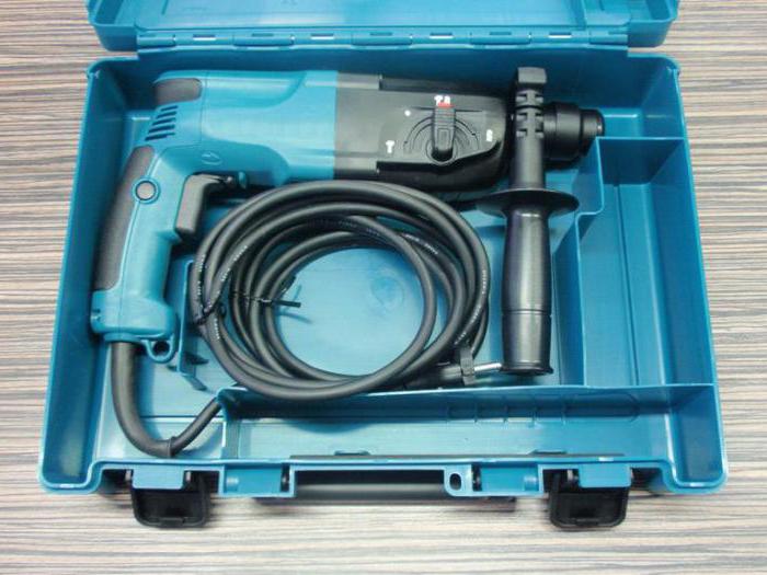
In our country, one of the most popular perforators is "Makita 2450". And it is not by chance. After all, "Makita 2450" has good characteristics, and its assembly scheme allows you to perform with your own hands. Makita is known as a high-quality Japanese manufacturer, but the HR 2450 model is produced in China. To draw conclusions about the quality of the equipment presented, you should consider user reviews about "Makita 2450", left in different sources. Having deepening knowledge about the instrument presented, it will simply conclude about the feasibility of its purchase.
General characteristics
"Makita 2450" is known among builders and repairmen as rather functional professional instrument. It is simple and reliable in operation, has ease and good balancing. Due to this, "Makita 2450" will serve enough for a long time. It has a good dust protection system, which makes the operation of equipment durable.
Its popularity is explained by the possibility of repairing the perforator "Makita 2450" at home. It will not be necessary to spend a lot of money for its service. However, before the process of assembling 2450, it should be familiar with the technology of its disassembly and repair.
Specifications
A definite set of qualities has a perforator "Makita 2450". The characteristics represented by the manufacturer in the instructions are as follows.
The weight of the tool is only 2.4 kg. The fastenings of the drill is carried out by the SDS + system. The perforator is intended for crushing, drilling and drilling drilling. He has three modes of operation. Number of revolutions idle move Equally 1100 per minute, and the maximum number of shocks is 4500 per minute. The strength of the translational movement at the maximum is 2.7 J. Maximum drilling diameter:
- for wood - 32 mm;
- for metal - 13 mm;
- for concrete - 24 mm;
- for the hollow crown - 54 mm.
There are also additional functions Perforator "Makita 2450". Characteristics Selects the presence of a safety clutch, reverse, blocking the power button, as well as electronic speed adjustment.
Power supply power is 780 W. Cable length is 4 m.
Signs of fakes
Because of the great popularity of the presented equipment, it is often necessary for the cases of his fake. Exist characteristicswhich define an unreal perforator HR 2450. These include a short cord (about 0.5 m). The letters on the black clasp suitcase in the fakes are matte, and the original is brilliant.
In the photo of the perforator in the instructions at the present product, the background is light gray, almost white. The copy will have a dark, deaf color of the image of the image.
If the suitcase of the HR 2450 model is indicated as the manufacturer of Japan, this is an unreal tool. On the original it is written: "Made in p.r.c.", i.e. "Made in China."
Includes the rubberized handle on which the serial number is specified. All parts of the suitcase should also contain each of its own designation. For fake, the handle is not made of rubber, but from plastics. It should also become a signal about the need to refuse to buy such a tool.
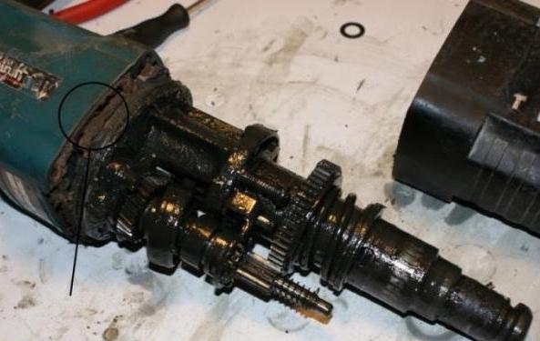
Disassembly scheme
In the process of implementing the repair of the submitted equipment, the user must be able to disassemble the tool. The scheme of the injection of the perforator "Makita 2450" has many nodes and elements. For repair, not all of them should be known. Here are the most basic elements that represent the scheme ("Makita 2450" - the device is very complex).

The first is a stop ring. It participates in the process of dismantling the cartridge cover. Next comes ring shut-off. It keeps the ball for fixing the bora. Its guides serve a washer and a conic spring.
Reducer with the engine connect 4 screws. In the scheme there is a lot rubber detailswhich when they are wear frequent cause breakdowns.
These knowledge is enough to repair at home. Next, you should familiarize yourself with the technique of its holding.
Features of independent repairs
Repair of the perforator "Makita 2450" with their own hands for several reasons.

Representatives of the service center implement troubleshooting on a specific algorithm. This leads to quite high costs.
There is also a great opportunity that employees of the company's representation will hold just a planned inspection, the need of which is doubtful. And pay for it anyway will have to.
If the node or several of them will still be replaced, the service staff will supply only licensed details "Makita 2450". Repairs in this case may be comparable in cost with buying a new tool. All these facts speak in favor of self-configuration or replace equipment parts.
Repairs
"Makita 2450" is repaired with its own hands in the presence of certain knowledge and skills. The technology of inspection and replacement of parts of the HR 2450 model is quite simple. It involves making a disassembly tool, after which the whole old lubricant is removed, dust, dirt. Damaged nodes are replaced with new ones. Then all the details of the perforator are collected together. It is necessary to familiarize yourself with each point of such works. They can be carried out in the field of cartridge, mode switch, perforator housing.
For repair, first remove the cartridge, then the speed switch. After that, repair inside the housing. Replacing lubrication and worn rubber elements.
Cartridge
With a flat screwdriver, a cartridge disassembled. Repair of the perforator "Makita 2450" are starting with this element with their own hands. Pulling the cartridge cover, remove the rubber boot. A lock ring is dismantled. Then removed the lid of the cartridge and metal ring. It locks the Bura fixing ball in the barrel. He is removed and metal washerThe conic spring is taken without effort.
The cause of the breakdown may be exhaust details. It is detected if the drill is not snapped automatically, without pressed the lid. Checking all the details, detect the cause of the breakdown. Old elements are purified from dirt and old lubrication. The ball is thickly processed by new oil. The conical spring is set by a narrow side to the resistor.
The guide washer must press it so as to be lower than the hole in the trunk. Repair of the perforator "Makita 2450" with a cartridge area requires fixing the ball in the well. All items are collected in reverse order.
Switch modes
For disassembly, the T-shaped latch is removed on the switch knob. Use a 2 mm screwdriver for this. Very neatly need to press the paws of the latch. It is pulled out. The red retainer must be kept so that it does not fly off the springs.

After these actions, the switch knob should be rotated to the leftmost position. So the protrusions will coincide with the grooves of the editor's case. The switch is easily removed. The retainer gets together with the spring. The rubber ring on the switch knob should pose a thin screwdriver and remove it. It prevents the leakage of the housing.
The McITE 2450 Perforator Assembly Scheme in the switch area involves a specific sequence. All items and landing space are cleaned from old mud. Gusto lubricate two metal pins and rubber ring. It is put on the switch. The spring is inserted into the handle, then the retainer. He should not pop up when a latch will be installed in the case.
Then the switch is inserted into the gearbox. In this case, the handle is sent to the sector between the designation of the combined mode and the impact. It does not insert until the end. The switch should be rotated until the drilling mode and slightly further. In this case, do not forget to press the button of the retainer so that it does not interfere with the movement.
Then rotate the switch clockwise and the latch is pressed to the end.
Switch malfunctions
In the process of familiarizing with the question, how to collect "Makita 2450", you should find out the frequent failure of the switch. They can be caused by wear of metal pins. In this case, there will be no one of the modes. You will need to replace the switch. This should be done in the event of a breakdown of landing protrusions.
If the rubber ring was worn out, a slight leakage of lubrication will occur. You will have to replace it.
It happens that the retainer breaks the key with which it is attached to the shutoffs of the gearbox. Can be damaged by the paws of the retainer. To avoid all the above damage, you need to carefully handle the tool.
Case reducer
To remove the case from the gearbox, it is necessary to raise the trunk of the tool up. The perforator should be pressed to the workbench, at the same time pulling the shell up. In this position, all the details remain in their places.

After their revision, checking and replacing the gearbox is installed in place. All its elements must be located in its original form. The necessary items need to be lubricated.
In the process of assembly, the gearbox must be cleaned by kerosene or gasoline. Next, the shell is worn to its original place. The mode switch in it should not be.
Malfunctions in the gearbox
The housing of the HR 2450 model is characterized by high strength, breakdown in this node is rather rare. But it happens that certain troubles occur here. If the housing got along with it means, its seat is strongly worn out. When this item is cleaned extremely strongly, the case should be replaced.
Sometimes the seat of the intermediate shaft is broken. Repair is assumed similar to the first case.
Shaka Gear Case has if the construction dust damaged it (it happens extremely rarely) or non-acceptable actions of the repairman, it is changed along with the case.
The same procedure is performed in case of failure of the modes switch holes. The listed types of damage are characteristic of fake instances.
 Why you can not give icons
 Is it possible to give icons as a gift: Signs, the opinion of the Church
 A year ago left her husband, and now I do not know what to do