Covering pipelines of fire extinguishing installations. Test pipelines - Installation of automatic fire extinguishing in cable structures Terms and definitions
- Appendix A (recommended). Act of delivery and acceptance of the installation of gas fire extinguishing commissioning Appendix B (recommended). Act of fire testing of the gas fire extinguishing installation application in (recommended). Protocol for carrying out autonomous testing of the installation of the gas fire extinguishing application G (recommended). Act of testing pipelines for strength Appendix D (recommended). The act of testing pipelines for tightness with the definition of pressure drop during testing the application E (informational). Bibliography
State Standard of the Russian Federation GOST R 50969-96
"Installations of gas fire extinguishing automatic. General technical requirements. Test methods"
(put into effect by the Resolution of the State Standard of the Russian Federation of November 13, 1996 N 619)
With changes and additions from:
Automatic Gas Fire Extinguishing Systems. General Technical Requirements. Test Methods.
Introduced for the first time
1 area of \u200b\u200buse
This standard applies to centralized and modular automatic installation of bulk gas fire extinguishing (hereinafter - installations) and establishes general technical requirements for installations and methods of their tests.
The requirements of this standard can also be used in designing, installation, testing and operation of local gas fire extinguishing installations.
3.6 fire extinguishing substance: The required amount of fire extinguishing agent, which is stored in order to restore the calculated amount or reserve of fire extinguishing agent
3.10 modular gas fire extinguishing unit:Automatic fire extinguishing installation containing one or more gas fire extinguishing modules that are placed in a protective room or next to it
3.14 duration of filing GOTV: Time from the start of the release of GOTS from the nozzle to the protected room until the release of 95% of the mass of the GOTV, which is required to create a regulatory fire extinguishing concentration in the protective room
3.20 centralized gas fire extinguishing installation: Installation of gas fire extinguishing, in which gas vessels, as well as distribution devices (if available), placed indoors of fire extinguishing station
4 General Technical Requirements
4.1 Development, acceptance, maintenance And the operation of the installations should be carried out in accordance with the requirements of GOST 12.1.004, GOST 12.1.019, GOST 12.2.003, GOST 12.2.007.0, GOST 12.3.046, GOST 12.4.009, GOST 21128, GOST 21752, GOST 21753, SP 5.13130 , Rules ,,, These Standard and Technical Documentation, approved in the prescribed manner.
4.2 Installations on the execution and category of placement in terms of the effects of climatic factors of the external environment must be compliance with GOST 15150 and operating conditions.
4.3 Equipment, products, materials, gotals and gases for their displacement used in the installation must have a passport, documents certifying their quality, duration of continuity and comply with the conditions of application and project specification to install.
4.4 Installations should use GOTV, allowed to use in the prescribed manner.
4.5 Nitrogen, the technical characteristics of which correspond to GOST 9293 should be applied as a gas-oscillator. It is allowed to use air for which the dew point must be no higher than minus 40 ° C.
4.6 vessels (vessels of various design versions, cylinders installed separately or in batteries, etc.) used in fire extinguishing installations, must comply with the requirements of the rules.
4.7 Installations should be provided with devices for monitoring the number of GOTV and gas-displacer pressure in accordance with the requirements of GOST R 53281 and GOST R 53282.
Installations in which Step under operating conditions are compressed gas is allowed to provide only pressure control devices.
4.8 The composition of the installation, placement of its elements and their interaction must comply with the requirements of the project to install and technical documentation for its elements.
4.9 Installations should provide inertia (without taking into account the delay time of the release of GOTV, which is necessary for the evacuation of people, stopping technological equipment, etc.) not more than 15 seconds.
4.10 The duration of the supply of GOTS must comply with the requirements of existing regulatory documents.
4.11 Installations should ensure the concentration of GOTV in the amount of protected premises are not lower than the normative.
4.12 Filling vessels of GOTOS and gas-gas-out (pressure) must comply with the requirements of the project for the installation and technical documentation on the vessels, GOTV, as well as the conditions for their operation. For the cylinders of one size in the installation, the calculated values \u200b\u200bfor the filling of GOTV and the gas-oscillator should be the same.
4.13 Centralized installations, in addition to the estimated number of GOT, should have a 100% reserve in accordance with SP 5.13130. The stock of GOTS in centralized installations is not provided.
4.14 Modular installations, in addition to the estimated number of GOTV, should have a margin in accordance with SP 5.13130. The reserve of GOTS in modular installations is not provided. The stock of GOTS should be stored in modules similar to installation modules. The stock of GOTS should be prepared for installation in the installation.
4.15 Mass of GOTS in each vessel of installation, including vessels with a reserve of GOTV in centralized installations and modules with a reserve of GOTV in modular installations, should be at least 95% of the calculated values, the pressure of the gas-displacement (if available) - at least 90% of their calculated values \u200b\u200btaking into account the temperature of operation.
It is allowed to control only the pressure of the GOTV, which under the operation of the installations are compressed gases. At the same time, the pressure of the GOTS should be at least 95% of the calculated values, taking into account the temperature of operation.
The frequency and technical means of monitoring the preservation of GOTV and Gaza-Promescriber must comply with technical documentation for modules, batteries and isothermal fire tanks.
4.16 The supply pipelines of the GOTV and their compounds in the installations should provide strength at pressure at least, and for motivating pipelines and their compounds - no less (- the maximum pressure of the GOTS in the vessel under operating conditions is the maximum gas pressure (air) in the promoting system).
4.17 Intelligent pipelines and their connections in the installations should ensure tightness at a pressure of at least.
4.18 Installation facilities must provide:
a) automatic and manual remote start;
b) disconnection and restoration of automatic start;
c) automatic switching of power from the main source to the backup when the voltage is turned off at the main source;
d) health care (break, short circuit) fire alarm loops and connecting lines;
e) health care (breaking) of electrical control circuits of starting elements;
e) pressure control in starting cylinders and motivating pipelines;
g) control of the health of sound and light alarm (on call);
h) disabling sound alarm;
and) the formation and issuance of a command impulse to control the technological and electrical equipment, ventilation, air conditioning, as well as fire alert devices.
4.19 Installations should provide a delay in the release of the GOTV to the protected room with an automatic and manual remote start for the time required for evacuation from the people's room, but at least 10 s from the moment of inclusion in the room of the evacuation alert devices.
The time of complete closing of the flaps (valves) in the air ducts of ventilation systems in the protected room should not exceed the delay time of the release of MOTOS into this room.
4.20 In the protected room, as well as in adjacent, having output only through the protected room, when the installation is triggered, the lighting devices should be turned on (the light signal in the form of inscriptions on the light scoreboard "Gas - Leave!" And "gas is not to enter!") And sound Alerts in accordance with GOST 12.3.046, SP 5.13130 \u200b\u200band GOST 12.4.009.
4.21 In the premises of the fire station or another room with personnel leading round-the-clock duty, light and sound alarms should be provided in accordance with the requirements of SP 5.13130.
4.22 Centralized settings must be equipped with local launch devices. Started elements of local installation devices, including switchgear, Must have signs indicating the names of protected premises.
5.6 At the venue of the test or repair work Installations should be installed warning signs "Caution! Other hazards" according to GOST 12.4.026 and explaining the inscription "Tests are tested!", And also posted instructions and safety rules.
5.7 Pyopatrons used in installations as simulators when conducting tests, should be placed in assemblies that ensure the safety of their use.
5.8 pneumatic tests The pipelines are no longer allowed.
Pneumatic strength tests are not allowed for pipelines located in the premises if there are people or equipment in them, which may be damaged when the pipeline is destructed.
5.9 The actions of the staff in the premises in which the movement of the GOTOS when the settings are triggered must be specified in the safety instructions applied at the facility.
5.10 Included in the protected room after the release of steps to it until the end of the ventilation is allowed only in insulating respiratory protection agents.
5.11 The installation with the installation should be allowed by persons who have passed special briefing and training in safe work methods, checking the knowledge of the safety and instructions in accordance with the post being held in relation to the work performed according to GOST 12.0.004.
6 Security Requirements ambient
6.1 In terms of environmental protection, the installation should ensure the relevant requirements of technical documentation for fire extinguishes during operation, maintenance, testing and repair.
7 Completeness, marking and packaging
7.1 Requirements for completeness, labeling and packaging of elements included in the settings should be specified in the technical specifications on these elements.
8 Procedure for testing
8.2 For the period of testing, measures must be provided to ensure the fire safety of the protected object.
8.3 Installation tests should be carried out by enterprises (organizations), operating installations with attracting, if necessary, third-party organizations and take shape (Appendix A).
8.4 When accepting installation facilities, assembly and commissioning organizations should present:
Executive documentation (a set of work drawings with changes made in them);
Passports or other documents certifying the quality of products, equipment and materials applied in the production of installation work.
8.5 Integrated installation tests should be carried out:
When accepting operation;
During the period of operation at least once every 5 years in accordance with the RD 25.964 (except for the tests of 4.9-4.11).
Before accepting, the installation should be run in to identify malfunctions that can lead to a false triggering of the installation. The duration of the runoff sets the installation and commissioning organization, but not less than 3 days.
The run is carried out with the connection of the starting chains to the simulators of 9.5, which electrical characteristics correspond to the executive devices (activators) of the installation. It should be fixed by the automatic registration device of all cases of fire alarm triggering or controlling the automatic installation of the installation, followed by the analysis of their causes.
In the absence of false positives or other disruptions, the installation is translated into automatic operation. If, during the run, the failures continue, the installation is subject to re-regulation and running.
8.6 Tests of installations for inspection of inertia, duration of the supply of GOTV and the fire extinguishing concentration of GOTV in the amount of protected premises (4.9-4.11) are not mandatory. The need for their experimental verification is determined by the Customer or, in the case of retreat from the design standards that affect the parameters verified, the officials of the management bodies and units of the State Fire Service in the implementation of the State Fire Supervision.
9 Test Methods
9.1 Tests are carried out under normal climatic conditions of tests according to GOST 15150, if special conditions are not specified by the test method.
9.2 In the tests where the requirements for the accuracy of measurement of the parameter specified as a value with one-sided limit (except for temporary parameters) are guided by the following: The possible measurement error must be taken into account in the measured parameter in such a way as to rise. Reliability of its definition.
For example, the requirement is given that the mass of GOTV in the vessel should be at least 95 kg. When weighing on scales having accuracy kg, a weight of 96 kg was obtained. Given the measurement error in the direction of increasing the reliability of determining the parameter, we obtain the test result - 94 kg. Conclusion: Installation for this test does not satisfy the specified requirement.
9.3 The relative error of measurements of temporary parameters should not exceed 5%.
9.5 Testing for the interaction of installation elements (4.8) is carried out using instead of a compressed air.
Vessels with GOTS are disconnected from installation. Instead of them (vessels), simulators are connected to the starting circuits of the installation (electrical stations, lamps, self-sash devices, pyropathyroids, etc.) and one or two vessels filled with compressed air to a pressure corresponding to the pressure in vessels with GOTOS at test temperatures. In installations with pneumopus, motivating pipelines and wider-starting sections are also filled with compressed air to the appropriate operating pressure. Automatic installation starts. Hereinafter, the automatic start of installations are carried out by activating the necessary number of fire detectors or imitating their devices in accordance with the design documentation for the installation. The operation of fire detectors should be implemented by imitating the corresponding fire factor.
The installation is considered to be withstood the test if the operation of nodes and instruments meets the technical documentation for test equipment and design documentation for installation.
Test results are executed by the protocol (application B).
9.6 Inertia testing (4.9) Test is carried out with automatic startup installation (9.5).
Time is measured from the moment of the last fire detector responding to the start of the expiration of GOTS from the nozzle, after which the feeding of the GOTV can be discontinued.
Hereinafter, when testing, the moments of the beginning or end of the expiration of GOTS from the nozzle must be determined using thermocouples, pressure sensors, gas analyzers, audio and video recording of jets (liquefied GOT) or other objective control methods.
It is allowed instead of GOTV, which, when stored in a vessel, are compressed gas, apply another inert gas or compressed air. Gas pressure in the vessel should be equal to the pressure of GOTV in the installation. It is allowed instead of GOTV, which, when stored in a vessel, are liquefied gas, apply other model liquefied gas.
The installation is considered to be sustained the test if the measured time is excluding the delay time for evacuation, stopping technological equipment, etc. Complies with the requirements of 4.9.
9.7 Test to determine the duration of the supply of GOTV (4.10), which, when stored, is liquefied gas, is carried out as follows. In the vessels of the installation, 100% of the mass of the GOTOS required to create a regulatory fire extinguishing concentration in the protected room are refilled. Paste the installation and feeding the GOTV to the protected room. Measure from the moment of expiration from the nozzle until the end of the expiration from the nozzle of the liquid phase of the GOTS (9.6).
When tested, the installation with GOTV, which is compressed with compressed gas, measure from the moment of starting the expiration of GOTS from the nozzle until the calculated pressure in the installation (vessel, pipeline) of the calculated pressure corresponding to the release from the installation of 95% of the mass of the GOTOS required to create a regulatory extinguishing Concentration in the protective room.
The duration of the submission is allowed to determine using the model gas instead of the GOTOS gas. In this case, the duration of the feed is calculated based on the results of the experiment by definition bandwidth Pipelines installation.
The installation is considered to be withstood test if the measured feed time meets the requirements of the current regulatory documents.
9.8 Ensuring the regulatory extinguishing concentration of GOTV in the protected room (4.11) is tested by measuring the concentration of GOTS under cold tests or on the extinguishing of model foci of fire during fire tests.
9.8.1 Concentration measurement points (model foci) are located at levels 10, 50 and 90% of the room height. The number and location of the points of measurement of concentration (model foci of fire) at each level is determined by the test methodology. The location of the measurement points of the concentration (model foci of fire) should not be located in the zone of direct exposure to the jets of the GOTS supplied from the nozzles.
9.8.3 In firing tests, model foci of fire-tanks with a fuel load are used, which, as a rule, use combustible materials that are typical for the protected room. The amount of combustible material is determined by the test methodology, it should be sufficient to ensure the duration of the burning for at least 10 minutes after the start of the gotto to the protected room. It is forbidden to fill the tank with combustible materials, which can create an explosive concentration in the room.) In the vessel, weighing on scales or by calculation based on the measurement results of the level, temperature, pressure.
Checking the pressure of the GOTOS and the gas-oscillator in the vessel is performed by pressure gauge.
The installation is considered to be withstood the test if the mass (pressure) of the GOTV and the gas-oscillator in the vessels corresponds to 4.15.
9.10 Test of the installation pipelines and their compounds for strength (4.16) are carried out as follows.
Before testing, pipelines are subjected to external inspection. As a test liquid, as a rule, water is used. Pipelines supplying fluid must be previously tested. Instead of nozzles, in addition to the last on the distribution pipe, screw the plugs. Pipelines are filled with liquid and then installed the plug instead of the last nozzle.
When testing, the pressure lift should be carried out in steps:
the first stage is 0.05 MPa;
second step - ();
third step - ();
fourth stage - ().
At the intermediate levels of pressure lifting, an excerpt is made for 1-3 minutes, during which the absence of pressure in the pipes is set to the pressure gauge or other instrument. The pressure gauge should be not lower than the 2nd accuracy class.
Under pressure () pipelines withstand 5 minutes. Then the pressure is reduced to () and inspected. At the end of the test, the fluid is drained and producing pipelines with compressed air.
Application is allowed instead of a test liquid of compressed inert gas or air while compliance with safety requirements.
Pipelines are considered withstanding the test if the pressure drop is not detected and the release, cracks, leaks, fogging are not detected. Tests draw up an act (application d).
9.11 The tightness test of the planting pipelines (4.17) is carried out after they are tested for strength (9.10).
Air or inert gas is used as a test gas. In pipelines create pressure equal to.
Pipelines are considered with the test, if within 24 hours there will be no pressure drop in more than 10% and the release, cracks and leaks are not detected. To identify defects, when inspection of pipelines, it is recommended to use foaming solutions. Pressure should be measured by a manometer not lower than the 2nd accuracy class.
Tests for tightness are drawn up with an act (Appendix D).
9.12 Checking the automatic and manual remote installation of installation (4.18, enumeration A) perform without a release from the installation of GOTS. The vessels with GOTS are disconnected from the launchers and connect simulators (9.5). Alternately carry out the automatic and remote installation start.
The installation is considered to be withstood the test if the installation automatically and remote startup starts, all simulators in the starting circuits occurred.
9.13 Checking off and restoring the automatic installation start setting (4.18, the enumeration b) is carried out by exposure to a shutdown device (for example, by opening the door to the room or for installations with a pneumopus switching of the corresponding device on the motivating pipeline) and restore the automatic startup.
The installation is considered to be sustained the test if the automatic start is turned off and restores the light alarm in accordance with the technical documentation for the equipment test.
9.14 Checking the automatic switching of power from the main source to the backup (4.18, the listing c) is carried out in two stages.
At the first stage, when you run the installation in standby mode, the main power supply is turned off. Must work light and sound alarms in accordance with the technical documentation for the test equipment. Connect the main power supply.
At the second stage, tests are carried out in accordance with 9.12. In the period from the moment of inclusion of automatic or remote starting before issuing the installation of start-up pulses to simulators, the main power supply is turned off.
The installation is considered to be withstood the test if the light and sound alarms are triggered at the first stage in accordance with the technical documentation for the test equipment and at the second stage all simulators in the starting chain are triggered.
9.15 Testing means of monitoring the health of the fire alarm and connecting lines (4.18, the listing g) is carried out by alternate opening and short circuit of the loops and lines.
9.16 Testing means of monitoring the health circuits of the power controls (4.18, the listing D) is carried out by opening the trigger chain.
The installation is considered to be withstood test if the light and sound alarm is triggered in accordance with the technical documentation for the test equipment.
9.17 The test of air pressure controls in starting cylinders and a motion pipeline of installation (4.18, enumeration E) is carried out with a decrease in pressure in the induct pipeline by 0.05 MPa and in launch cylinders - by 0.2 MPa from the calculated values.
The air pressure drop is allowed to imitate by closing the contacts of the electrocontact pressure gauge or in another way.
The installation is considered to be withstood test if the light and sound alarm is triggered in accordance with the technical documentation for the test equipment.
9.18 Test to control the serviceability of light and sound alarm (4.18, lifying G) Make the switching on the display devices of the light and sound alarm.
Installation is considered to be withstood test if light and sound alarms are triggered in accordance with the technical documentation for the equipment test.
9.19 Test of the disabling means of sound alarm (4.18 enumeration h) is performed as follows. After the sound alarm is triggered (for example, when checking on 9.13 -9.17) include a device for disconnecting sound alarm.
The installation is considered to be withstood test if the sound alarm is turned off and in the absence of automatic recovery of sound alarm, light alarm is triggered in accordance with the technical documentation for the test equipment.
9.20 Testing of the command impulse formation (4.18, enumeration and) perform without a release from the installation of GOTS. Vessels with hobbies are disconnected from launchers.
To the output terminals of the element forming a command impulse, a device for managing technological equipment or measuring device. The instrument for measuring the parameters of the command impulse is chosen in accordance with the technical characteristics of the equipment test and indicate the test method. Perform an automatic or remote installation start.
The installation is considered to be withstood the test if the device is triggered to control technological equipment or the command pulse is recorded by a measuring instrument.
9.21 Checking the delay time (4.19) and inclusions on the alert devices (4.20) are carried out without the release of GOTS with an automatic and remote start of installation. The installation chains of the installation instead of vessels with GOTOS connected simulators (9.5).
After starting the installation in the protected room, as well as in adjacent, having the output only through the protected room, control the inclusion of the lighting devices (the light signal in the form of an inscription on the light scoreboard "Gas - Leave!") And sound alert. Measure the time from the moment the alert devices are turned on until the simulators are triggered in the installation launchers.
Then check the inclusion of the light alert device (the light signal in the form of an inscription on the light scoreboard "Gas is not to enter!") Before the protected room.
The installation is considered to be sustained test if the measured time corresponds to the delay required at 4.19 and the alert devices are turned on in accordance with 4.20.
10 Transportation and Storage
Requirements for transportation and storage of elements that make up the settings should be specified in the technical specifications on these elements.
______________________________
* Installations designed or reconstructed after the introduction of this standard.
** Test methods are designed to verify installations that use newly developed equipment, substances, products, materials.
Why "LLC New Wave"
special offer for the price for users of the Bizorg site;
timely fulfillment of obligations made;
diverse payment methods.
We are waiting for your call!
FAQ.
- How to leave an application?
To leave an application for "crimping pipelines of fire extinguishing installations" Contact the company "Ltd. New Wave" by contact data, which are indicated in the upper right corner. Be sure to specify that the organization found on the site of Bizorg.
- Where to learn more complete information about the organization "Ltd. New Wave?
For details on the organization, go to the upper right corner by reference with the company name. Then go to your interesting tab with the description.
- The offer is described with errors, the contact number of the phone does not respond, etc.
If you have problems with the interaction with the "New Wave LLC" - inform the identifiers of the organization (10676) and goods / services (50780) to our user support service.
Service information
"Covering pipelines of fire extinguishing installations" can be found in the following category: "Design and maintenance of fire extinguishing systems".
In the pipe wiring there is a two-phase flow of a gas fire extinguishing agent (liquefied and gaseous). For the hydraulic balance, you must adhere to several rules:
- The length of the area after the removal or tee must be 5-10 nominal diameters.
- The orientation of the outputs from the tee must lie in one horizontal plane.
- The use of crosses is unacceptable.
- Maximum removal of the nozzle from the gas fire extinguishing module is not more than 50-60 meters along the horizon and no more than 20-25 meters in height.
- The volume of the pipe wiring should not exceed 80% of the volume of the liquid phase of GOTS
Gas fire extinguishing pipeline
Black tube necessarily needs anti-corrosion protection. There are two opinions in what color to paint the pipeline of gas fire extinguishing systems. The first thing is to use red, as it is fire equipment. The second thing is to be painted in yellow, like this pipeline transporting gases. The norms allow painting to any color, but require to make an alphabet or digital labeling of the pipeline.
The design of gas fire extinguishing systems is a rather complex intellectual process, the result of which the workable system becomes reliably, and effectively protect the object from fire. This article discusses and analyzedproblems arising from the design of automaticgas fire extinguishing installations. Estimated maybedata data systems and their effectiveness, as well as relativespossible options for optimal constructionautomatic gas fire extinguishing systems. Analysisthese systems are made in full compliance withcP Rules 5.13130.2009 and other rulessNiP, NPB, GOST and federal laws and ordersRF on automatic fire extinguishing installations.
Chief Engineer project LLC "ASPT SpecialAvtomatika"
V.P. Sokolov
To date, one of the most effective means of extinguishing fires, in premises to be protected automatic installations Fire extinguishing AUPT in accordance with the requirements of the SP 5.13130.2009 Appendix "A", are the installations of automatic gas fire extinguishing. The type of automatic extinguishing method, the extinguishing method, the type of fire extinguishing agents, the type of equipment of fire automation installations is determined by the designer organization, depending on the technological, constructive and volume and planning features of protected buildings and premises, taking into account the requirements of this list (see paragraph A.3. ).
The use of systems where the fire extinguishing agent during fire automatically or remotely in manual start-up mode is supplied to the protected room is especially justified when protecting expensive equipment, archival materials or values. Automatic fire extinguishing installations allow you to eliminate the ignition of solid, liquid and gaseous substances, as well as electrical equipment under voltage at an early stage. This extinguishing method may be volumetric - when creating a fire extinguishing concentration throughout the volume of the protected room or local - if the fire extinguishing concentration is created around the protected device (for example, a separate unit or a unit of technological equipment).
When choosing optimal option Management of automatic fire extinguishing installations and the choice of fire extinguishing agent is usually guided by the norms, technical requirements, features and functionality of protected objects. Gas fire extinguishes with the correct selection practically do not damage the protected object in it with equipment with any industrial and technical purpose, as well as the health of the staff working in the protected premises with a permanent stay. The unique gas ability to penetrate the cracks into the most inaccessible places and effectively affect the focus of ignition gained the widespread distribution in the use of gas extinguishing substances in automatic gas fire extinguishing installations in all areas of human activity.
That is why automatic gas fire extinguishing installations are used to protect: data processing centers (data center), server, telephone bonds, archives, libraries, museum stoves, banks' cash repositories, etc.
Consider the varieties of fire extinguishing substances most commonly used in automatic gas fire extinguishing systems:
Cladon 125 (C 2 F 5 H) The regulatory bulk fire extinguishing concentration of n-heptane GOST 25823 is 9.8% of the volume (corporate name HFC-125);
Claudone 227EA (C3F7H) The regulatory bulk fire extinguishing concentration of n-heptane GOST 25823 is equal to - 7.2% of the volume (branded name FM-200);
Claudone 318C (C 4 F 8) The regulatory bulk fire extinguishing concentration of n-heptane GOST 25823 is - 7.8% of the volume (corporate name HFC-318C);
Cladon FC-5-1-12 (CF 3 CF 2 C (O) CF (CF 3) 2) Regulatory volumetric concentration of n-heptane GOST 25823 is equal to - 4.2% of the volume (NOVEC 1230 proprietary name);
Carbon dioxide (CO 2) The regulatory volumetric fire extinguishing concentration of n-heptane GOST 25823 is - 34.9% of volume (can be used without constant stay of people in the protective room).
We will not analyze the properties of gases and their principles of influence on the fire in the fire focus. Our task will be the practical use of these gases in automatic gas fire extinguishing installations, the ideology of constructing these systems in the design process, the issues of calculating the mass of the gas to ensure the regulatory concentration in the amount of protected room and determine the diameters of the supply and distribution pipe pipes, as well as the calculation of the exhaust area of \u200b\u200bthe nozzle .
In gas fire extinguishing projects when filling in the drawing stamp, on title sheets and in the explanatory note, we use the term automatic installation of gas fire extinguishing. In fact, this term is not entirely correct and correct will be the use of the term automated gas fire extinguishing.
Why is that! We look at the list of terms in the joint venture 5.13130.2009.
3. Terms and definitions.
3.1 Automatic Fire Extinguishing Installation Start: Starting installation from her technical means without human participation.
3.2 Automatic fire extinguishing installation (AUP): Installation of fire extinguishing, automatically triggered by exceeding the controlled factor (factors) of the fire of installed threshold values \u200b\u200bin the protected zone.
In the theory of automatic control and regulation there is a separation of terms Automatic control and automated control.
Automatic systems - This is a complex of software and technical means and devices working without human participation. The automatic system does not have to be a complex device complex, to control engineering systems and technological processes. This can be one automatic device that performs the specified functions according to a predetermined program without person.
Automated systems - This is a complex of devices that transform information into signals and transmitting these signals to the distance via the communication channel for measurement, alarm and management without human participation or with its participation of no more than one side of the transmission. Automated systems This is a combination of two automatic and manual control systems (remote) control systems.
Consider the composition of automatic and automated systems Control of active fire protection:
Funds for obtaining information information collection devices.
Means for transmitting information lines (Channels) communication.
Means for receiving, processing information and issuing control signals of the lower level local receptions electrotechnical devicesdevices and control and control stations.
Means for using information automatic regulators I.executive mechanisms and devices alerts of various purposes.
Means display and processing information, as well as automated top-level control - central control panel orautomated operator workplace.
Automatic installation of gas fire extinguishing augpt includes three launch modes:
- automatic (running from automatic fire detectors);
- remote (the launch is carried out from the manual fire detector located at the door to the protected room or the protection post);
- the local (from the mechanical device of the manual start-up located on the starting module "cylinder" with a fire extinguishing agent or next to the fire extinguishing module for liquid carbon dioxide MPJA structurally made in the form of isothermal capacity).
Remote and local start mode are performed only with human intervention. It means the correct decoding of augpt, will be the term « Automated gas fire extinguishing installation ».
Recently, the Customer in the coordination and approval of the project on gas fire extinguishing to work requires that the inertia of the fire extinguishing installation is indicated, and not just the estimated time delay of the outlet of the gas evacuation of the personnel of the premises.
3.34 Fire extinguishing installation inertia: Time from the moment the controlled factor of the fire threshold of the sensitive element of the fire detector, the sprinkler irrigator or the motivating device before the start of supplying the extinguishing agent in the protected zone.
Note - For fire extinguishing installations, which provide a time delay to the release of a fire extinguishing agent in order to safely evacuate people from a protected room and (or) to control technological equipment, this time is included in the inertia of the AUP.
8.7 Temporary characteristics (see SP 5.13130.2009).
8.7.1 Installation should provide a delay in the release of GOTV to the protected room with an automatic and remote start for the time required for evacuation from the room of people, disconnecting the ventilation (air conditioning, etc.), closing the flaps (fireproof valves, etc.), But not less than 10 seconds. From the moment of inclusion in the premises of devices for evacuation.
8.7.2 Installation should provide inertia (response time without taking into account the delay time of the GOTV) not more than 15 seconds.
The delay time of the release of the gas fire extinguishing agent (GOT) into the protected room is set by programming the algorithm for the operation of the station control gas fire exterior. The time required to evacuate people from the room is determined by calculating the special procedure. The time interval of delays to evacuate people from the protected room can be from 10 seconds. up to 1 min. and more. The delay time of the gas release depends on the dimensions of the protected room, the complexity of the flow in it technological processes, functional features installed equipment I. technical appointment, both separate rooms and industrial facilities.
The second part of the inertial delay in the installation of gas fire extinguishing over time is the product of the hydraulic calculation of the supply and distribution pipe with nozzles. The longer and harder the main pipeline to the nozzle, the greater the inertia of the installation of gas fire extinguishing. In fact, compared with the delay of time, which is necessary to evacuate people from the protected area, this value is not so big.
The inertia of the installation (the beginning of the gas expiration through the first nozzles after the opening of the shut-off valves) is MIN 0.14 seconds. and max. 1.2 sec. This result is obtained from the analysis of about a hundred hydraulic calculations of different complexity and with different compositions of gases, both chladones and carbon dioxide located in cylinders (modules).
Thus, the term "Inertia of gas fire extinguishing installation" It consists of two components:
Gas release delay time for safe evacuation of people from the room;
Time of technological inertiality of the installation itself when issuing GOTS
It is necessary to separately consider the inertia of the installation of gas fire extinguishing with carbon dioxide on the basis of the isothermal firefighter reservoir "Volcano" with different volumes of the vessel used. A structurally unified row form vessels with a capacity of 3; five; 10; sixteen; 25; 28; 30m3 on operating pressure 2,2mP and 3,3 mp. To configure the data of the vessels by shut-off and starting devices (s), depending on the volume, three types of shut-off valves are used with the diameters of the conditional passage of the outlet 100, 150 and 200mm. As an actuator in the shut-off device, a ball valve or disk shutter is used. As a drive, a pneumatic drive with a working pressure on the piston of 8-10 atmospheres is used.
Unlike modular installations, where the electrical start of the head lock-starting device is carried out almost instantly, even with the subsequent pneumatic launch of the remaining modules in the battery (see RIS-1), the disk shutter or ball valve open and close with a small time delay, which can be 1-3 seconds. Depending on the equipment manufactured by the manufacturer. In addition, the discovery and closure of this equipment ZPU in time due to the structural features of the shut-off valves is far from a linear dependence (see RIS-2).
The figure (RIS-1 and RIS-2) presents a graph on which one axis is the value of the average carbon dioxide flow, and the time value of the time. The area under the curve within the regulatory time determines the calculated amount of carbon dioxide.
Average carbon dioxide consumption Q M., kg / s, determined by the formula
where: m. - the calculated amount of carbon dioxide ("mg" on SP 5.13130.2009), kg;
t.- The regulatory time of supply of carbon dioxide, p.
with modular carbon dioxide. 
Rice-1.
1-
t.o. - opening time of the shut-off and starting device (s).
t.x. – the end time of the outlet of the CO2 gas through the CPU.
Automated gas fire extinguishing installation
With carbon diquses based on isothermal capacity MPJU "Volcano".
 Rice-2.
1- the curve that determines the consumption of carbon dioxide over time through the CPU.
The storage of the main and reserve reserve of carbon dioxide in isothermal containers can be carried out in two different separate tanks or in one. In the second case, there is a need to close the shut-off and starting device after the output of the main reserve from isothermal container during an emergency situation of fire extinguishing in a protective room. This process is shown in the figure as an example (see RIS-2).
Using isothermal capacity MPJU "Volcano" as a centralized fire extinguishing station into several directions, implies the use of a shut-off-starting device (s) with a function open-close function to cut off the desired (calculated) amount of fire extinguishing agent for each gas fire extinguishing direction.
The presence of a large distribution network of the gas fire extinguishing pipeline does not mean that the expiration of the gas from the nozzle will not begin earlier than the CPU completely opens, therefore the opening time of the exhaust valve cannot be included in the technological inertia of the installation during the production of GOTV.
A large number of automated gas fire extinguishing installations is used in enterprises with different technical production to protect technological equipment and installations, both, with normal operating temperatures, and with a high level of operating temperatures on the working surfaces of the units, for example:
Gas pumping units of compressor stations dividing by type
drive motor on gas turbine, gas engine and electric;
High pressure compressor stations with an electric motor drive;
Generator sets with gas turbine, gas engine and diesel
drives;
Manufacturing technological equipment By comprementing I.
preparation of gas and condensate on oil and gas condensate fields, etc.
Let's say working surface Gas turbine drive housings for an electrical generator in certain situations can reach sufficiently high heating temperatures exceeding the self-ignition temperature of some substances. When an emergency situation occurs, a fire, on this technological equipment and further eliminating this ignition using an automatic gas fire extinguishing system, there is always a possibility of recurrence, the occurrence of re-fire when contacting hot surfaces with natural gas Or turbine oil that is used in lubrication systems.
For equipment where there are hot work surfaces in 1986. VNIIPO The USSR Ministry of Internal Affairs for the USSR Ministry of Gas Industry was developed a document "Fire protection of gas-pumping units of compressor stations of main gas pipelines" (summarized recommendations). Where it is proposed to apply individual and combined fire extinguishing installations to extinguish such objects. Combined fire extinguishing installations imply two input queues into action of fire extinguishers. The list of combinations of fire extinguishers are available in a generalized methods. In this article we consider only the combined installations of gas fire extinguishing "Gas Plus Gas". The first phase of the gas fire extinguishing of the object complies with the standards and requirements of the SP 5.13130.2009, and the second queue (proceeding) eliminates the possibility of re-fire. The method of calculating the mass of gas for the second stage is given in generalized recommendations. See "Automatic gas fire extinguishing installations" section.
To start a gas fire extinguishing system of the first stage in technical installations without the presence of people, the inertia of the gas fire extinguishing installation (gas start delay) must correspond to the time of the hardware of the technical means and disabling the equipment air cooling. The delay is envisaged in order to prevent the depths of the gas extinguishing substance.
For the gas fire extinguishing system, the second stage recommends a passive method for preventing recurrence of re-fire recurrence. The passive method implies the inertization of the protected room for a time sufficient for the natural cooling of the heated equipment. The feeding time of the fire extinguishing agent into the protected zone is calculated and depending on the technological equipment can be 15-20 minutes and more. The operation of the second stage of the gas fire extinguishing system is carried out in the mode of maintaining a given fire extinguishing concentration. The second phase of gas fire extinguishing is included immediately at the end of the first stage. The first and second phase of gas fire extinguishing for feeding the extinguishing agent should have its own separate pipe wiring and a separate hydraulic calculation of the distribution pipe with nozzles. The time intervals, between which the opening of the cylinders of the second line of fire extinguishing and the stock of the fire extinguishing agent is determined by the calculations.
As a rule, for extinguishing above the described equipment, carbon dioxide CO 2 is used, but Claudones 125, 227ea and others can be used. Everything is determined by the value of the protected equipment, the requirements for the effects of the selected fire extinguishing agent (gas) on equipment, as well as efficiency when extinguishing. This issue lies entirely in the competence of specialists engaged in the design of gas fire extinguishing systems in this area.
The control circuit of such an automated combined gas fire extinguishing installation is rather complex and requires a very flexible logic of control and management work from the control station. It is necessary to carefully approach the choice of electrical equipment, that is, to gas fire control devices.
Now we need to consider general issues on the placement and installation of gas fire extinguishing equipment.
8.9 Pipelines (see SP 5.13130.2009).
8.9.8 The system of distribution pipelines, as a rule, should be symmetric.
8.9.9 Internal volume of pipelines should not exceed 80% of the volume of the liquid phase of the estimated amount of GOTV at a temperature of 20 ° C.
8.11 Nozzles (see SP 5.13130.2009).
8.11.2 Nozzles should be placed in a protective room, taking into account its geometry and ensure the distribution of GOTV all over the volume of the room with a concentration not lower than the normative.
8.11.4 The difference in the costs of GOTV between two extreme nozzles on one distribution pipe should not exceed 20%.
8.11.6 In one room (protected volume), nozzles of only one sizes should be applied.
3. Terms and definitions (see SP 5.13130.2009).
3.78 Distribution pipe: Pipeline on which rods, sprayers or nozzles are mounted.
3.11 Branch of the distribution pipeline: Section of a row of a distribution pipe located on one side of the feed pipeline.
3.87 Row of distribution pipeline: A combination of two branches of the distribution pipe located on one line from two sides of the supply pipeline.
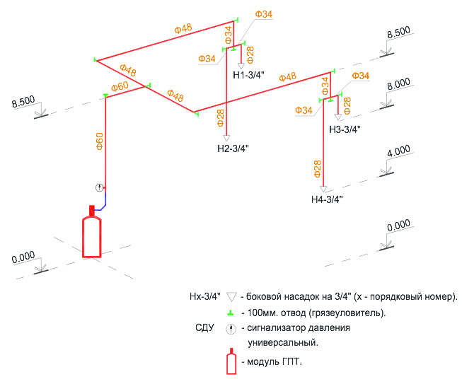
Increasingly, when coordinating project documentation on gas fire extinguishing, it is necessary to deal with different interpretation of certain terms and definitions. Especially if the axonometric scheme of pipeline layout for hydraulic calculations sends the customer himself. In many, the organization of gas fire extinguishing systems and water fire extermination are among the same specialists. Consider two layout of gas fire extinguishing pipes, see Fig-3 and Rice-4. The "comb" type scheme is mainly used in water fire extinguishing systems. Both schemes shown in the figures are used in the gas fire extinguishing system. There is only a restriction for the "comb" type scheme, it can only be used to extinguish carbon dioxide (carbon dioxide). The regulatory time of carbon dioxide comes into a protected room is no more than 60 seconds, and it does not matter this modular or centralized installation of gas fire extinguishing.
The fill time of the carbon dioxide of the entire pipeline depending on its length and diameters of the tube can be 2-4 seconds, and then the entire pipeline system to distribution pipelines on which nozzles are converted, both in the system, water fire extinguishing in the "feed pipe". Under all the rules of the hydraulic calculation and the correct selection of internal diameters of pipes, the requirement will be carried out in which the difference in the costs of the GOTV between two extreme nozzles on one distribution pipe or between two extreme nozzles on the two extreme rows of the supply pipeline, such as a row 1 and 4, will not exceed twenty%. (See Catching Clause 8.11.4). The operating pressure of carbon dioxide in front of the nozzles will be approximately the same, which will ensure the uniform consumption of the fire extinguishing agent of the step through all the nozzles over time and the creation of a regulatory concentration of gas at any point of the protected room after a period of 60 seconds. Since the start of installing gas fire extinguishing.
Another case of a variety of fire extinguishing substances - chladones. The regulatory time of the reference to the protected room for modular fire extinguishing is not more than 10 seconds, and for centralized installation no more - 15 seconds. etc. (See SP 5.13130.2009).
fire extinguishingaccording to the "comb" type scheme.

Rice-3.
Hydraulic calculation with gas refrigeric gas (125, 227EA, 318C and FC-5-1-12) For an axonometric scheme for wiring a "comb" type, the main requirement of the ruled rules is ensuring a uniform consumption of fire extinguishing agent through all nozzles and ensure the distribution of GOTOS throughout the volume of the protected room with a concentration is not lower than the normative (see sawing clause 8.11.2 and paragraph 8.11.4). The difference in consumption of the GOTS family of chladone through the nozzles between the first and last rows can reach the values \u200b\u200bof 65% in the place of permissible 20%, especially if the number of rows on the supply pipeline reaches 7 pcs. and more. Obtaining such results for the gas of the chladone family can be explained by the process physics: the process of the process in time, the fact that each subsequent row takes part of the gas on itself, gradually increasing the length of the pipeline from the row to the row, the dynamics of resistance to the gas movement through the pipeline. It means that the first row with nozzles on the feed pipeline is in more favorable working conditions than the last row.
The rule says that the difference in the costs of the step between two extreme nozzles on one distribution pipeline should not exceed 20% and say nothing about the consumption difference between rows on the feed pipeline. Although another rule says that nozzles should be placed in a protective room, taking into account its geometry and ensure the distribution of GOTV all over the volume of the room with a concentration not lower than the normative.
Gas installation pipeline layout plan
Fire extinguishing on a symmetric scheme.

Rice-4.
How to understand the requirement of the array of rules, the system of distribution pipelines, as a rule, should be symmetric (see Catching 8.9.8). The "Comb" type pipeline layout system Installation of gas fire extinguishing also has a symmetry relative to the feed pipeline and at the same time does not provide the same gas consumption of the chladone brand through the nozzles throughout the volume of the protected room.
On Figa-4 shows a pipeline wiring system for installing gas fire extinguishing on all symmetry rules. This is determined by three features: the distance from the gas module to any nozzle has one and the tight length, the diameters of the pipes to any nozzle are identical, the number of bends and their direction is similar. The difference in gas costs between any nozzles is practically zero. If the architecture of the protected room is necessary, some kind of distribution pipeline with a nozzle to lengthen or move to the side, the cost difference between all the nozzles will never go beyond 20%.
Another problem for gas fire extinguishing installations is the large height of the protected rooms from 5 m. And more (see RIS-5).
AXONOMOMETRIC SCHEME OF THE GAS FIRE PIPERING PUBLISHin the room one volume with a large height of the ceilings.
Rice-5.
This problem occurs when protecting industrial enterprises, where production workshops are subject to defense may have ceilings up to 12 meters high, specialized archives buildings, with ceilings reaching 8 meters altitudes and above, storage and maintenance hangars various special equipment, gas pumping stations and petroleum products and T .. The generally accepted maximum height of the installation of the nozzle relative to the floor in the protective room, widely used in gas fire extinguishing installations, is usually no more than 4.5 meters. It is at this height that the developer of this equipment and checks the work of its nozzle for compliance with its parameters with the requirements of SP 5.13130.2009, as well as the requirements of other regulatory documents of the Russian Federation on fire safety.
With a high height of industrial premises, for example, 8.5 meters, the technological equipment itself will uniquely be located at the bottom at the production site. With volumetric gas fire extinguishing installation in accordance with the rules of the SP 5.13130.2009, the nozzles should be located on the ceiling of the protected room, at a height of not more than 0.5 meters from the surface of the ceiling in strict accordance with their technical parameters. It is clear that the height of the production premises is 8.5 meters does not match technical characteristics nozzle. The nozzles should be placed in the protected area, taking into account its geometry and ensure the distribution of GOTV all over the volume of the room with a concentration not lower than the normative (see sawing. 8.11.2 from SP 5.13130.2009). The question of how long the regulatory concentration of gas will be equalized in time throughout the volume of the protected room with high ceilings, and what rules it can be adjusted. One solution is seen this issue This conditional division of the total amount of protected premises in height into two (three) equal parts, and on the borders of these volumes every 4 meters in the direction down the wall symmetrically set additional nozzles (see RIS-5). Additionally, the installed nozzles make it possible to quickly fill the volume of the protected room with a fire extinguishing agent with the provision of a regulatory concentration of gas, and that much more importantly ensure the fast supply of the extinguishing agent to technological equipment at the production site.
Submitted pipe wiring diagram (see Riga-5) is more convenient on the ceiling to have nozzles with spraying gun by 360o, and on the walls of the nozzle with side spraying of GOTV on the 180-1 single size and equal to the calculated area of \u200b\u200bholes for spraying. As the rule is read in one room (protected volume), nozzles of only one sizes should be applied (see sawing section 8.11.6). True, the definition of the term nozzles of one size in SP 5.13130.2009 is not given.
For hydraulic calculation of the distribution pipe with nozzles and calculating the mass of the required amount of gas extinguishing agent to create a regulatory fire extinguishing concentration in a protected amount, modern computer programs are used. Earlier, this calculation was made in manual using special approved techniques. It was difficult and long in time by action, and the result was quite greatest. To obtain reliable results of the hydraulic calculation of the pipe wiring, there was a great experience of a person dealing with the calculations of gas fire extinguishing systems. With the advent of computer and training programs, hydraulic calculations have become available to a large circle of specialists working in this area. Computer program "Vector", one of the few programs allowing you to optimally solve all sorts of complex tasks in the field of gas fire extinguishing systems with minimal loss of time on calculations. To confirm the reliability of the calculation results, the verification of hydraulic calculations was carried out on the computer program "Vector" and a positive expert opinion was obtained No. 40 / 20-2016 of 03/31/2016. The Academy of GPS of the Emergencies Ministry of Russia for the use of the system of hydraulic calculations "vector" in the gas fire extinguishing facilities with the following fire extinguishers: Cold 125, Cladon 227EA, Cladon 318c, FC-5-1-12 and CO2 (carbon dioxide) production of LLC ASPT SpecialAvtomatika.
Computer program of hydraulic calculations "Vector" frees the designer from routine work. It contains all the rules and rules of the joint venture 5.13130.2009, it is within these restrictions that calculations are performed. A person inserts only its source data into the program to calculate and makes edits if the result is not satisfied.
Finally I would like to say, we are proud that in recognition of many specialists, one of the leading Russian manufacturers of automatic gas fire extinguishing installations in the field of technology is LLC ASPT Special Automation.
The company designers have developed a number of modular installations for various conditions, features and functionality of protected objects. The equipment fully complies with all Russian regulatory documents. We carefully follow and study world experience in developing in our area, which allows the use of the most advanced technologies in the development of its own production facilities.
An important advantage is that our company does not only design and establishes fire extinguishing systems, but also has its own production base for the manufacture of all the necessary equipment for fire extinguishing - from modules to collectors, pipelines and nozzles for spraying gas. Own gas stations gives us the opportunity to as soon as possible make a refueling and examination large number Modules, as well as carry out comprehensive tests of all newly developed gas fire extinguishing systems (GPT).
Cooperation with leading world producers of fire extinguishes and manufacturers of GOTS in Russia allows LLC ASPT SpecialAvtomatik to create multidisciplinary fire extinguishing systems using the safest, highly efficient and widespread compositions (Claudones 125, 227EA, 318C, FC-5-1-12, carbon dioxide ( CO 2)).
LLC "ASPT SpecialAvtomatika" offers not one product, but a single complex is a complete set of equipment and materials, project, installation, commissioning and subsequent maintenance above the listed fire extinguishing systems. In our organization is regularly held free Training in design, installation and commissioning of equipment manufactured, where you can get the most complete answers to all the questions that arise, as well as get any consultation in the field of fodder protection.
Reliability and high quality - our main priority!
A technical and economic comparison showed that in order to protect the premises of more than 2000 m3 in the UGP, it is more expedient to use isothermal modules for liquid carbon dioxide (mp3).
Moju consists of an isothermal reservoir for CO2 storage, with a capacity of 3000 l to 25000l, shut-off and starting device, instruments for controlling the amount and pressure CO2, refrigeration units and control cabinets.
From the HPP on our market, applying isothermal tanks for liquid carbon dioxide, the mission of Russian production in its technical characteristics is superior to foreign products. Isothermal reservoirs of foreign production must be installed in heated room. The mission of domestic production can be operated at ambient temperature up to minus 40 degrees., Which allows you to install isothermal tanks outside the buildings. In addition, in contrast to foreign articles, the design of the Russian mission allows the submission to the protected room CO2, dosing by weight.
Cladon Nozzles
For the uniform distribution of GOTV in the volume of the protected room on the distribution pipelines, the UGP is installed nozzles.
Nozzles are installed on the outlet openings of the pipeline. The design of the nozzle depends on the type of gas supplied. For example, for the supply of refrigeration 114V2, which under normal conditions is a liquid, two-rigs were previously used with the impact of the jets. Currently, such nozzles are recognized as ineffective regulatory documents recommended to replace them on hooks of a jack-type or centrifugal, providing fine spliced \u200b\u200bchladone type 114V2.
For supplying refrigerations type 125, 227EA and C02, a radial type nozzle is used. In such nozzles, the flows of gas incoming in nozzles and extending gas jets are approximately perpendicular. Radial type nozzles are divided into ceiling and walls. Ceiling nozzles can supply gas jets to sector with an angle of 360 °, walls - about 180 °.
An example of the use of radial-type ceiling nozzles as part of augps is shown on fig. 2.

The placement of nozzles in the protective room is carried out in accordance with the technical documentation of the manufacturer. The number and area of \u200b\u200bthe outlet openings of the nozzles is determined by the hydraulic calculation, taking into account the flow rate and the map of the dispenser specified in the technical documentation for the nozzle.
AUGP pipelines are made from seamless pipeThat ensures the preservation of their strength and tightness in dry rooms for a period of up to 25 years. Applied pipe connection methods - welded, threaded or flange.
To maintain the expenditure characteristics of pipeline wiring over a long period of operation, the nozzles should be made from corrosion-resistant and durable materials. Therefore, advanced domestic firms do not apply nozzles from aluminum coating alloys, and only brass nozzles use.
The right choice of UGP Depends on many factors.
Consider the main of these factors.
Method of fire protection.
UGPs are designed to create a gas environment that does not support the combustion in the protected room (volume). Therefore, there are two ways to fire extinguishing: volumetric and locally volumetric. The overwhelming majority applies a volumetric method. Local in terms of volume from an economic point of view is beneficial in the case when the protected equipment is installed indoors of a large area, which regulatory requirements No need to fully protect.
In NPB 88-2001, regulatory requirements are given at the locally and volume method of fire extinguishing only for carbon dioxide. Based on the data of the regulatory requirements, it follows that conditions exist under which the location of the extinguishing method is economically more expedient for volume. Namely, if the size of the room is 6 times and more exceeds the conditionally dedicated volume occupied by the equipment to be protected by the APT, then in this case the local extinguishing method is cost-effective in volume.
Gas fire extinguishing substance.
The choice of gas fire extinguishing agent should be made only on the basis of a feasibility study. All other parameters, including the efficiency and toxicity of GOTS cannot be considered as determining for a number of reasons.
Any of the permitted to use is quite efficient and the fire will be eliminated if a regulatory concentration will be created in the protected amount.
An exception to this rule is the extinguishing of materials prone to degeneration. Studies conducted in FGU VNIIPO EMERCOM of Russia under the direction of A.L. Chibisov showed that the complete cessation of burning (fiery and decline) is possible only when the three-time carbon dioxide is submitted. Such a number of carbon dioxide reduces the concentration of oxygen in the burning zone below 2.5% vol.
According to regulatory requirements in Russia (NPB 88-2001), it is forbidden to produce a gas extinguishing agent into the premises if people are located there. And this restriction is correct. The causes of people's death in fire shows that more than 70% of the deaths of people are fatal outcome due to the poisoning of combustion products.
The cost of each of the GOTS is significantly different from each other. At the same time, knowing only the price of 1 kg of gas fire extinguishing agent cannot be estimated the cost of fire protection 1 m 3 volume. Unambiguously, it is only possible to say that protection of 1 m 3 of volume with GOTV N 2, AR and "Inergen" at a cost of 1.5 times and more expensive than the remaining gas fire extinguishing substances. This is due to the fact that the listed GOTOS is stored in gas fire extinguishing modules in a gaseous state, which requires a large number of modules.
UGPs are two types: centralized and modular. The selection of the type of gas fire extinguishing type depends on the number of protected premises on one object, secondly, from the availability of a free space in which the fire extinguishing station can be placed.
When protecting on one object of 3 and more rooms, located apart at a distance of 10 m, from an economic point of view, centralized UGP is preferable. Moreover, the cost of the protected volume decreases with increasing the number of rooms protected from one fire extinguishing station.
At the same time, centralized UGP compared to modular, has a number of shortcomings, namely: the need to perform a large number of requirements of the NPB 88-2001 to the fire extinguishing station; The need for laying on the building of pipelines from fire extinguishing station to protected premises.
Gas fire extinguishing modules and batteries.
Gas fire extinguishing modules (IHL) and batteries are the main element of the installation of gas fire extinguishing. They are intended for storing and producing GOTV to the protected room.
IHP consists of a cylinder and a locking device (s). Batteries, as a rule, consist of 2 and more gas fire extinguishing modules, combined with a single collector of factory execution. Therefore, all the requirements that are presented to the IHL are similar for both batteries.
Depending on the gas extinguishing agent used in the UGP of the Gas Fire extinguishing substance, MHP should meet the listed requirements.
IHL, reflected by chladones of all brands should ensure the release time of GOTV not exceeding 10 s.
The design of gas fire extinguishing modules, filled with 2, N 2, AR and "inergen", should ensure the release time of the GOTV not exceeding 60 s.
In the process of operation, the IHP should ensure the control of the mass of the payroll.
Control of the mass of refrigeration 125, chladone 318c, chladone 227ea, N 2, Ar and "inergen" is carried out using a pressure gauge. With a decrease in the pressure of the gas-displacer in the cylinders with the above chladones above 10%, and N 2, Ar and "inergen" by 5% of the nominal IHP should be sent for repair. The difference in pressure loss is caused by the following factors:
With a decrease in the pressure of the gas-displacer, the mass of chladone in the vapor phase is partially lost. However, this loss is not more than 0.2% of the initial reflection of the mass of the chladone. Therefore, a pressure limit equal to 10% is caused by an increase in the release time of the GOTOS from the UGP as a result of a decrease in the initial pressure, which is determined based on the hydraulic calculation of the gas fire extinguishing installation.
N 2, Ar and "Inergen" are stored in gas fire extinguishing modules In a compressed state. Therefore, the decrease in pressure by 5% of the initial value is an indirect method of losing the mass of gotat on the same value.
Monitoring the loss of the mass of GOTV, displaced from the module under pressure from its own saturated vapor (chladone 23 and CO 2), should be carried out by a direct method. Those. A gas fire extinguishing module, fastened with chladone 23 or CO 2, during operation should be installed on a weight device. At the same time, the weight device should ensure control of the loss of the mass of the gas fire extinguishing substance, and not the total mass of the step and module, with an accuracy of 5%.
The presence of such a weight device provides that the module is installed or suspended on a strong elastic element, the movement of which changes the properties of the strain sensor. The electronic device reacts to these changes, which gives an alarm signal when changing the parameters of the strain sensor above the installed threshold. The main drawbacks of the tensometric device are to ensure the free movement of the cylinder on a solid metal-mounted design, as well as negative influence External factors - connective pipelines, periodic jokes and vibrations during operation, etc. increase the metal consumption and product dimensions, problems with installation increase.
In MPTU modules 150-50-12, MPTU 150-100-12 applied a high-tech method for monitoring the preservation of GOTV. The electronic mass control device (UKM) is built directly into the locking device (PC) of the module.
All information (Massop, calibration date, service date) is saved in the MCM storage device and can be displayed on the computer. For visual control, the module's CPU is equipped with an LED, which gives signals about normal operation, reducing the mass of GOTS by 5% or more or malfunction to the UKM. Moreover, the cost of the proposed gas control device in the module is much smaller than the cost of a strain gauge weight device with a control device.
Isothermal module for carbon liquid dioxide (MIJO).
Miscellates consists of a horizontal tank for storage CO 2, a lock-starting device, the amounts of quantity control and pressure control devices, refrigeration units and control shield. Modules are intended to protect the premises of up to 15 thousand. 3. Maximum capacity mission - 25t CO 2. The module is stored, as a rule, a working and backup reserve CO 2.
Additional advantage Mozhu is the possibility of its installation outside the building (under a canopy), which allows you to significantly save production areas. In heated room or warm boxing, only mpg control devices and Distribution devices UGP are installed (if available).
IHL with a capacity of cylinders up to 100 liters, depending on the type of combustible load and the filled GOTOS allow to protect the room with a volume of not more than 160 m 3. To protect the premises of the larger volume requires installation of 2 or more modules.
A technical and economic comparison showed that in order to protect the premises of more than 1500 m 3 in the UGP, it is more expedient to use isothermal modules for liquid carbon dioxide (mew).
Nozzles are intended for uniform distribution of GOTV to the volume of protected room.
The placement of nozzles in the protective room is carried out in accordance with the factory of the manufacturer. The number and area of \u200b\u200bthe outlet openings of the nozzles is determined by the hydraulic calculation, taking into account the flow rate and the map of the dispenser specified in the technical documentation for the nozzle.
The distance from the nozzles to the ceiling (overlap, suspended ceiling) should not exceed 0.5 m when using all GOTS, with the exception of N 2.
Pipe layout.
The layout of pipelines in the protective room, as a rule, should be symmetrical with an equal removal of nozzles from the main pipeline.
Installation pipelines are performed from metal pipes. The pressure in the installation pipelines and diameters is determined by the hydraulic calculation according to the methods agreed in the prescribed manner. Pipelines must withstand pressure when tested for strength and tightness of at least 1.25 rract.
When used as a GOT ROOM, the total volume of pipelines, including a collector, should not exceed 80% of the refrigerant phase of the refrigerant in the installation.
Tracing of distribution pipelines of installations that use chladone should be carried out only in the horizontal plane.
When designing centralized installations using chladones, attention should be paid to the following points:
- connect the main piping of the room with a maximum volume closer to the battery with GOTS;
- with a serial connection to the station collector with the main and reserve reserve, the most remote from the protected premises should be the main supply from the condition of the maximum reference output from all cylinders.
The right choice of gas fire extinguishing installation UGP depends on many factors. Therefore, the purpose of this work is to show the main criteria affecting the optimal choice of UGP and the principle of its hydraulic calculation.
Below are the main factors affecting the optimal choice of UGP. First, the type of combustible load in the protective room (archives, focusing, radio-electronic equipment, technological equipment, etc.). Secondly, the magnitude of the protected volume and its leaks. Third, the type of gas fire extinguishing agents of GOTV. In the fourth, the type of equipment in which the GOTS must be stored. Fifth, Type of UGP: centralized or modular. The last factor can only take place if you need fire protection two or more rooms on one object. Therefore, we consider the mutual influence of only four above the listed factors. Those. In the assumption that the facility requires fire protection only one room.
Sure, right choice UGP should be based on optimal technical and economic indicators.
It should be especially noted that any of the permitted GOTOS liquidates the fire regardless of the type of combustible material, but only when creating a regulatory extinguishing concentration in the protected volume.
The mutual influence of the factors listed above on the technical and economic parameters of the UGP will be assessed from the condition that the following GOTV: Cladon 125, reference 318c, reference 227EA, reference 23, CO 2, N 2, AR and mixture (N 2, AR and CO 2), having a trademark "Inergen".
According to the method of storage and methods of controlling the GOTV in the MMP gas fire extinguishing modules, all gas fire extinguishes can be divided into three groups.
The 1st group includes chladone 125, reference 318c and reference 227ea. These chladones are stored in the IHL in a liquefied form under pressure of the gas-displacer, most often - nitrogen. Modules with listed chladones, as a rule, have a working pressure not exceeding 6.4 MPa. The control of the amount of chladone during the operation of the installation is carried out according to the pressure gauge installed on the IHL.
Claudone 23 and CO 2 make up the 2nd group. They are also stored in liquefied form, but they are displaced from the IHL under pressure from their own saturated vapors. The operating pressure of modules with the listed GOTS must have a working pressure of at least 14.7 MPa. During operation, the modules must be installed on weighing devices that provide continuous control of the mass of chladone 23 or CO 2.
The 3rd group includes N 2, AR and inergen. Data from GOTOS is stored in the IHL in a gaseous state. Further, when we evaluate the advantages and disadvantages of GOTS from this group, only nitrogen will be considered. This is due to the fact that N2 is the most efficient GOTV (has the smallest fire extinguishing concentration and at the same time the smallest cost). The mass control of the 3rd group's mass is carried out on a pressure gauge. N 2, AR or inergen are stored in modules at a pressure of 14.7 MPa and more.
Gas fire extinguishing modules, as a rule, have a container of cylinders not exceeding 100 liters. Modules with a capacity of more than 100 liters according to PB 10-115 are subject to registration in the Gosgortkhnadzor of Russia, which entails a sufficiently large number of restrictions on their use in accordance with the indicated rules.
The exceptions are isothermal modules for carbon liquid dioxide mobility with a capacity from 3.0 to 25.0 m3. These modules are designed and manufactured for storage in gas fire extinguishing systems of carbon dioxide in quantities exceeding 2500 kg or more. Movie equipped with refrigeration units and heating elementsIt allows you to maintain the pressure in the isothermal tank in the range of 2.0 - 2.1 MPa at ambient temperature from minus 40 to plus 50 degrees. FROM.
Consider on the examples, as each of the 4 factors affect the technical and economic indicators of the UGP. The mass of GOTS was calculated according to the method described in the NPB 88-2001.
Example 1. It is required to protect radio-electronic equipment indoors of 60 m 3. The room is conditional hermetic. Those. K2 \u003d 0. The results of the calculation in the table. one.
Table 1
Economic substantiation of the table in specific figures has a certain difficulty. This is due to the fact that the cost of equipment and gotto from companies - producers and suppliers has a different cost. However, there is a common trend in the fact that the cost of the gas fire extinguishing module increases with an increase in the capacity of the cylinder. The cost of 1 kg of CO 2 and 1 m 3 N 2 is close at a price and two orders of magnitude less than the cost of chladone. Table analysis. 1 shows that the cost of UGP with chladone 125 and CO 2 is comparable in magnitude. Despite the significantly higher cost of chladone 125 compared with carbon dioxide. The total price of refrigerant 125 - IHP with a capacity of 40 liters with a capacity of 40 liters will be comparable or even somewhat lower than the carbon dioxide set - IHP with a cylinder 80 L - weight device. It is uniquely to state a significantly greater value of UGP with nitrogen compared to the two previously considered options. Because 2 modules are required with a maximum volume. It will take more space to accommodate 2 modules in the room and, of course, the cost of 2 modules with a volume of 100 liters will always be larger than the module with a volume of 80 liters with a weight device, which, as a rule, 4 - 5 times the price is less than the module itself.
Example 2. The parameters of the room are similar to example 1, but it is required to protect non-radio-electronic equipment, but an archive. The results of the calculation is similar to the 1st example in Table. 2 We will bring in table. one.
table 2
Based on the analysis of Table. 2 can be unambiguously to say, and in this case, UGP with nitrogen at a cost is significantly higher than gas fire extinguishing installations with chladone 125 and carbon dioxide. But in contrast to the 1st example, in this case, it can be more clearly to note that the lowest cost has a treaty with carbon dioxide. Because With a relatively small difference in the cost between the IHL with a cylinder, a capacity of 80 l and 100 liters, the price of 56 kg of chladone 125 significantly exceeds the cost of the weight device.
Similar dependencies will be traced if the volume of the protected room is increasing and / or its leaks increases. Because All this is caused general increase The number of any kind of GOTS
Thus, only on the basis of 2 examples it can be seen that it is possible to choose the optimal UGP for the fire protection of the room, only after consideration, at least two options with various species GOTS
However, there are exceptions when the UGP with optimal technical and economic parameters cannot be applied due to certain restrictions imposed on gas fire extinguishes.
Such restrictions, first of all, refers to the protection of particularly important objects in the seismic zone (for example, objects of nuclear power, etc.), where installation of modules in seismic resistant frames is required. In this case, the use of chladone 23 and carbon dioxide is excluded, since modules with these GOTS should be installed on weight devices that exclude their rigid fastening.
In the fire protection of premises with constantly present personnel (air traffic, halls with nuclear power plants, etc.), restrictions on the toxicity of GOTS are presented. In this case, the use of carbon dioxide is excluded, since the volumeting fire extinguishing concentration of carbon dioxide in the air is fatal for humans.
When protecting the volumes of more than 2000 m 3 from an economic point of view, the use of carbon dioxide, refilled in a mission, compared with all the rest of GOTS, is the use of carbon dioxide.
After conducting a feasibility study, the number of GOTV, which is necessary to eliminate fire and a preliminary amount of IHP becomes a known.
Nozzles must be installed in accordance with the scrawl cards specified in the technical documentation of the manufacturer of the manufacturer of the nozzles. The distance from the nozzles to the ceiling (overlapping, suspended ceiling) should not exceed 0.5 m when using all GOTV, with the exception of N 2.
Pipe layout, as a rule, should be symmetrical. Those. Nozzles must be equal to the main pipeline. In this case, the consumption of retreats through all the nozzles will be the same, which will ensure the creation of a uniform fire extinguishing concentration in the protected amount. Typical examples of symmetric pipe wiring are shown on fig. 1 and 2..

When designing the pipe wiring, it should also take into account the correct compound of removal pipelines (rows, taps) from the main pipeline.
Conducting compound is possible only under the condition when the consumption of G1 and G2 is equal in size (Fig. 3).
 If G1? G2, then the opposite compounds of rows and taps with a main pipeline must be made in the direction of movement of the move at a distance L, exceeding 10 * d, as shown in Fig. 4. Where d is the inner diameter of the main pipeline.
No restrictions are superimposed on the spatial connection of pipes during the design of pipe wiring, there are no restrictions when applying GOTV, belonging to the 2nd and 3rd groups. And for pipe wiring UGP with the 1st group, there are a number of restrictions. This is caused by the following:
When reducing the chladone 125, the refrigeration of 318c or chladone 227ea in the IHP nitrogen to the desired pressure, partially nitrogen dissolves in the listed chladones. Moreover, the amount of dissolved nitrogen in chladones is proportional to pressure pressure.
 After opening the shut-off-starting device, the CPU of the gas fire extinguishing module under the pressure of the gas-displacer pressure with a partially dissolved nitrogen on the pipe wiring is received to nozzles and through them it goes into the protected volume. In this case, the pressure in the system (modules - pipe wiring) decreases as a result of the expansion of the volume occupied by nitrogen in the process of displacing the refrigeration, and the hydraulic resistance of the pipe wiring. A partial selection of nitrogen from the liquid chladone phase occurs and a two-phase medium is formed (a mixture of the liquid chladone phase is nitrogen gaseous). Therefore, a number of restrictions are superimposed on the pipe wiring of the UGP using the 1st group. The main meaning of these restrictions is aimed at preventing the separation of the two-phase medium inside the pipe wiring.
When designing and installing, all pipe wiring connections UGP should be performed as shown in Fig. 5A, 5B and 5V

and it is forbidden to perform in the species shown in Fig. 6a, 6b, 6c. In the drawings, the arrows shows the direction of the flow of the GOTO through the pipes.

In the process of designing an UGP in axonometric form, a pipe wiring diagram is performed, the length of the pipes, the number of nozzles and their high-altitude marks. For determining internal diameter The pipes and the total area of \u200b\u200bthe outlet openings of each nozzle are necessary to perform the hydraulic calculation of the gas fire extinguishing installation.
Manage automatic gas fire extinguishing installations
When choosing an optimal control of automatic gas fire extinguishing installations, it is necessary to be guided by the technical requirements, features and functional features of protected objects.
The main schemes for building gas fire extinguishing control systems:
- autonomous gas exhaust control system;
- decentralized gas fire extinguishing control system;
- centralized gas extinguishing system.
Other options are derived from these typical schemes.
To protect local (separately worthy) rooms per one, two and three directions of gas fire extinguishing, as a rule, the use of autonomous gas fire extinguishing systems is justified (Fig. 1). The autonomous gas extinguishing station is located directly at the entrance to the protected room and controls both threshold fire detectors, light or sound notification and remote and automatic starting of the gas fire extinguishing unit (GPT). The number of possible directions of gas fire extinguishing on this scheme can reach from one to seven. All signals from the autonomous gas fire extinguishing station come directly to the Central Dispatch District on the station's output panel.

Fig. one.Autonomous Gas Faivory Control Installations
The second typical scheme is a diagram of a decentralized gas control control, presented in Fig. 2. In this case, the autonomous gas extinguishing station is embedded in an existing and existing comprehensive object security system or newly designed. Signals from an autonomous gas extinguishing station come to the address blocks and control modules, which then transmit information to the central dispatch post on the central fire alarm station. A feature of the decentralized gas fire management control is that upon failure of individual elements. complex system Safety of the object The autonomous gas fire extinguishing station remains in operation. This system allows you to integrate any number of gas fire extinguishing directions, which are limited only by the technical capabilities of the fire alarm station itself.

Fig. 2.Decentralized gas fire extinguishing control into several directions
The third scheme is a diagram of a centralized control of gas fire extinguishing systems (Fig. 3). This system is applied in the case when the requirements for fire safety are priorities. The fire alarm system includes address and analog sensors that allow you to control the protected space with minimal errors and prevent false responses. False responses of the fire system occur due to the contamination of the ventilation systems, supply exhaust ventilation (Smoke hit from the street), strong wind, etc. Warning false positives in address and Analog Systems It is carried out by controlling the dust of the sensors.

Fig. 3. Centralized gas fire extinguishing management into several directions
The signal from address-analog fire detectors enters the central station of fire alarm, after which the data processed through the address modules and blocks come to autonomous system Gas fire control. Each sensor group is logically tied to its gas fire extinguishing direction. The centralized gas extinguishing system is calculated only on the number of station addresses. Take, for example, a station with 126 addresses (single-stove). Calculate the number of necessary addresses to maximize the premises. Control modules - automatic / manual, gas is served and a malfunction is 3 addresses plus the number of sensors indoors: 3 - on the ceiling, 3 - per ceiling, 3 - under the floor (9 pcs.). We get 12 addresses to the direction. For a station with 126 addresses, these are 10 directions plus additional addresses for managing engineering systems.
The use of centralized gas fire extinguishing management leads to the rise in the cost of the system, but significantly increases its reliability, makes it possible to analyze the situation (control of dusty of sensors), and also reduces the cost level of maintenance and operation. The need to install a centralized (decentralized) system occurs with additional management of engineering systems.
In some cases, in place of the modular gas fire extinguishing unit, fire extinguishing stations are used in the gas fire extinguishing systems of the centralized and decentralized type. Their installation depends on the area and the specifics of the protected room. In fig. 4 shows the system of centralized control of gas fire extinguishing with a flame station (OGS).

Fig. four.Centralized gas fire extinguishing control of several directions with a fire
The choice of the optimal version of the gas fire extinguishing option depends on the large number of source data. An attempt to summarize the most significant parameters of gas fire extinguishing systems and installations is presented in Fig. five.

Fig. five.Select the optimal option for installing gas fire extinguishing software
One of the features of AGPT systems automatically is the use of address-analog and threshold fire detectors as devices recording a fire when the fire extinguishing system is launched, i.e. Release of fire extinguishing agent. And here it should be noted that from the reliability of the fire detector, one of the cheapest elements of the fire alarm system and fire extinguishing system, depend on the efficiency of the entire expensive complex of fire automation and, therefore, the fate of the protected object! At the same time, the fire detector must meet two basic requirements: the early definition of fire and the absence of false positives. What depends on the reliability of the fire detector as an electronic device? From the level of development, quality of element base, assembly technology and final testing. The consumer is very difficult to understand all the variety of detectors presented today in the market. Therefore, many are focused on the price and availability of a certificate, although, unfortunately, it is not today a guarantee of quality. Only the units of fire detector manufacturers openly publish the figures of the refusal, for example, according to the Moscow manufacturer of Systems Sensor Fair Detectors, its products are less than 0.04% (4 products per 100 thousand). This is definitely a good indicator and the result of multistage testing of each product.
Of course, only the address-analog system allows the customer to be absolutely confident in the performance of all its elements: smoke and heat sensors controlling the protected room are constantly polled by the fire management station. The device monitors the state of the loop and its components, in the case of a decrease in the sensor sensitivity, the station automatically compensates for it by installing the corresponding threshold. But when using chaasadres (threshold) systems, the sensor failure is not determined, and the loss of its sensitivity is not tracked. It is believed that the system is in working condition, but in reality the fire management station in the event of a real fire will not work accordingly. Therefore, when installing automatic gas fire extinguishing systems, it is preferable to use targeted-analog systems. Their relatively high cost is compensated by unconditional reliability and qualitative decrease in the risk of fire.
In general, the working draft RP of the gas fire extinguishing unit consists of an explanatory note, the technological part, the electrical part (in this paper is not considered), the specifications of equipment and materials and the estimation (at the request of the customer).
Explanatory note
The explanatory note includes the following sections.
Technological part.
In the subsection, the technological part is given a brief description of the main components of the UGP. The type of selected gas fire extinguishing agent of GOTV and the gas-displacer is indicated, if available. For chladone and mixture of gas fire extinguishing substances, a fire safety certificate number is reported. The type of IHL gas fire extinguishing modules (batteries) selected for the storage of the gas fire extinguishing agent, the fire safety certificate number is given. A brief description of the main elements of the module (battery), the method of controlling the mass of GOTS The parameters of the MHP electrical start (battery) are given.
1. General Provisions.
In chapter general provisions The name of the object is given for which the working draft UGP is made, and the rationale for its implementation. Regulatory and technical documents are given, on the basis of which project documentation has been completed.
The list of basic regulatory documents used in designing UGP is given below. NPB 110-99
NPB 88-2001 with meas. №1
Due to the fact that there is a permanent job on improving regulatory documents, designers must constantly adjust this list.
2. Purpose.
This section indicates how to install gas fire extinguishing and the functions performed.
3. Brief description of the protected object.
This section generally provides a brief description of the premises to be protected by the UGP, their geometric dimensions (volume). It is reported on the presence of raised floors and ceilings with a volumetric method of fire extinguishing or the configuration of the object and its location with local in volume. Information about the maximum and minimum temperature and humidity of the air, the presence and characteristics of the ventilation and air conditioning system, the presence of constantly open opening and extremely permissible pressures in protected areas are indicated. Data on the main types of fire load, the categories of protected premises and zone classes are given.
4. Basic design solutions. This section has two subsections.
It is reported on the selected type of nozzles for the uniform distribution of the gas extinguishing agent in the protected volume and the adopted standards of release of the estimated mass of GOTV.
For centralized installation, the type of distribution devices and the fire safety certificate number is given.
Formulas that are used to calculate the mass of the gas fire extinguishing agent of the UGP, and the numerical values \u200b\u200bused in the calculations are the numerical values \u200b\u200bof the main values: the adopted regulatory fire extinguishes for each protected volume, the density of the gas phase and the residue of the GOTOS in modules (batteries), the coefficient that takes into account the losses of the gas fire extinguishing substance From modules (batteries), the residue of GOTV in the module (batteries), the height of the protected room above sea level, the total area of \u200b\u200bconstantly open openings, the height of the room and the filing time of the GOTS.
The time calculation of the evacuation time of people from premises, which are protected by gas fire extinguishing installations and indicates the time of stopping the ventilation equipment, the closure of fire-graded valves, air dampers, etc. (if available). At the time of evacuation of people from the room or stopping the ventilation equipment, the closure of fire-graded valves, air dampers, etc. Less than 10 s Recommended Time Delay Time to receive 10 s. If all or one of the limiting parameters, namely, the estimated time of the evacuation of people, the time of stopping the ventilation equipment, the closure of fire-graded valves, air dampers, etc. exceeds 10 s, then the delay time of the release of GOTS must be taken by greater value or close to him but in most side. It is not recommended to artificially increase the delay time of the release of GOTOS for the following reasons. First, UGPs are designed to eliminate the initial stage of the fire, when the destruction of the enclosing structures and, above all, the windows. The emergence of additional openings as a result of the destruction of enclosing structures with a developed fire, not taken into account when calculating the required amount of GOTS, will not allow the normative fire extinguishing concentration of the gas fire extinguishing agent in the room after the operation of the UGP. Secondly, an artificial increase in free combustion time leads to unreasonably large material losses.
In the same subsection, according to the results of calculations of the maximum permissible pressures, carried out by the requirements of paragraph 6 of GOST R 12.3.047-98, it is reported that it is necessary to establish additional openings in the protected premises to reset the pressure after the assignment of the UGP or not.
- Electrical part.
In this subsection it is reported on the basis of what principles, fire detectors are selected, their types and numbers of fire safety certificates are given. The type of receiving and control and control instrument and the number of its fire safety certificate is indicated. A brief description of the basic functions that performs the device.
- Electrical part.
- Principle of installation.
This section has 4 subsections in which it is described: "Automatic Mode is enabled";
- mode "Automation is disabled";
- remote Start;
- local start.
- Power supply.
This section indicates which category of power reliability includes an automatic installation of gas fire extinguishing and in what diagram the instruments and equipment included in the installation should be carried out.
- Composition and placement of elements.
This section has two subsections.
- Technological part.
This subsection provides a list of the main elements, of which the technological part of the automatic installation of gas fire extinguishing, places and requirements for their installation.
- Electrical part.
This subsection provides a list of the main elements of the electrical part of the automatic gas fire extinguishing installation. Givens on their installation. The brands of cables, wires and conditions for their gasket are reported.
- Technological part.
- Professional and qualifying composition of persons working at the facility for maintenance and operation of the automatic fire extinguishing installation.
The composition of this section includes the requirements for personnel qualifications and its number when servicing the projected automatic gas fire extinguishing installation.
- Activities for labor protection and safe operation.
This section communicates regulationsOn the basis of which assembly and commissioning and maintenance and maintenance of automatic installation of gas fire extinguishing should be carried out. Requirements for persons allowed to maintain automatic gas fire extinguishing installation.
The activities that need to be performed after the operation is described in the event of a fire.
British standards requirements.
It is known that there are significant differences between Russian and European requirements. They are due to national peculiarities, geographical location and climatic conditions, the level of economic development of countries. However, the main provisions that determine the efficiency of the system should coincide. The following are comments to the British standard BS 7273-1: 2006 Part 1 on the gas volumetric extinguishing systems with electrical activation.
British standard BS 7273-1: 2006 Replaced Standard BS 7273-1: 2000. Fundamental differences of the new standard from previous version Marked in its preface.
- BS 7273-1: 2006 is a separate document, but in it (in contrast to the operating NPB 88-2001 *), references to the regulatory documents, together with which it should be used. These are the following standards:
- BS 1635 "Recommendations for graphic symbols and abbreviations for drawings of fire protection systems";
- BS 5306-4 "Equipment and installation of fire extinguishing systems" - part 4: "Technical requirements for systems with carbon dioxide";
- BS 5839-1: 2002 concerning fire detection systems and alerts for buildings. Part 1: "Norms and rules for the design, installation and maintenance of systems";
- BS 6266 "Norms and rules for protection against fire equipment installations";
- BS ISO 14520 (all parts), "Gas fire extinguishing systems";
- BS EN 12094-1, "Stationary Fire Systems - Components gas systems Fire extinguishing "- Part 1:" Requirements and Test Methods of Automatic Controls ".
Terminology
Definitions of all major terms are taken from BS 5839-1, BS EN 12094-1 standards, in the BS 7273 standard, only the few listed terms are defined.
- Automatic / manual mode switch and manual only - a system for transfering a system from an automatic or manual activation mode to manual activation mode (with a switch, as explained in the standard, can be made in the form of a manual switch in the control device or in other devices, or in the form of Separate door block, but in any case, switching system activation mode with automatic / manual on only manual or back) is provided:
- automatic mode (in relation to the fire extinguishing system) is a functioning mode in which the system is initiated without manual intervention;
- manual mode - the one in which the system can only be initiated by manual control.
- The protected area is an area located under the protection of the fire extinguishing system.
- The coincidence is the logic of the system in which the output signal is supplied in the presence of at least two independent input signals that are simultaneously present in the system. For example, the output signal to activate fire extinguishing is formed only after the fire is detected by one detector and, at least, when another independent detector of the same protected zone confirmed the presence of a fire.
- The control device is a device that performs all the functions necessary to manage the fire extinguishing system (in the standard it is indicated that this device can be made as a separate module or as an integral part of the automatic fire alarm system and fire extinguishing).
Design system
The standard also notes that the requirements for the protected area must be established by the designer during consultations with the client and, as a rule, by architect, specialists of contractors engaged in the installation of the fire alarm system and the automatic fire extinguishing system, fire safety experts, experts of insurance companies, responsible person From the Office Office, as well as representatives of any other interested departments. In addition, it is necessary to pre-schedule actions that, in the event of a fire, should be taken to ensure the safety of persons in the territory and the effective functioning of the fire extinguishing system. This kind of action should be discussed at the design stage and implement in the proposed system.
The system project must also comply with the standards of BS 5839-1, BS 5306-1 and BS ISO 14520. Based on the data obtained during the consultation, the designer is obliged to prepare documents containing not only a detailed description of the design solution, but, for example, and simply graphic Representation of the sequence of actions leading to the launch of the extinguishing agent.
System functioning
In accordance with the specified standard, the fire extinguishing system operation algorithm should be formed, which is given in graphical form. Annex to this standard provides an example of such an algorithm. As a rule, in order to avoid unwanted gas startup in the case of an automatic system operation mode, the sequence of events should assume a fire definition at the same time with two separate detectors.
The activation of the first detector should, at least, lead to an indication of the "Fire" mode in the fire alarm system and the inclusion of alert within the protected area.
The gas release from the extinguishing system should be monitored and indicated by the control device. To control the gas start, the pressure or gas flow sensor should be used, located in such a way as to control its release from any cylinder in the system. For example, in the presence of conjugate cylinders, gas production should be monitored from any container to the central pipeline.
The interruption of the communication between the fire alarm system and any part of the fire extinguishing control device should not affect the operation of fire sensors or to respond to the fire alarm system.
Requirement for improving performance
The fire alarm system and alert must be designed in such a way that in the event of a single damage to the loop (cliff or short circuit), it detected a fire on the protected area and, at least, left the possibility of switching on fire extinguishing manually. That is, if the system is designed in such a way that the maximum system controlled by one detector is x m 2, then with a single loop failure, each workable fire sensor must ensure control of the area to the maximum 2x m 2, the sensors must be distributed via the protected area evenly.
This condition can be performed, for example, by using two radial loops or one ring loop with short-circuit protection devices.
 Fig. one.System with two parallel radial loops
Indeed, when climbing or even with a short circuit of one of two radial loops, the second loop remains in a working condition. In this case, the detectors should ensure control of the entire area protected by each loop separately. (Fig. 2)
 Fig. 2.Alignment of detectors "couples"
A higher level of performance is achieved when using ring loops in address and address-analog systems with short circuit insulators. In this case, when the ring loop is cut, it is automatically converted into two radial, the breakdown location is localized and all sensors remain in the working condition, which saves the system functioning in automatic mode. With a short circuit of the ring loop, only devices are disconnected between two adjacent short circuit insulators, and therefore most of the sensors and other devices also remain workable.

Fig. 3. Open ring loop

Fig. four.Ring Circuit
A short circuit insulator is usually two symmetrically turned electronic keys, between which the fire sensor is located. Structurally, a short-circuit insulator can be built into the database, which has two additional contacts (input and output via a plus), or embedded directly into the sensor, in manual and linear fire detectors and in functional modules. If necessary, a short circuit insulator, made in the form of a separate module, can be used.
 Fig. five.Short-circuit insulator in the sensor database
Obviously, the system often used in Russia with one "two-step" loop does not meet this requirement. When breaking such a plume, a certain part of the area of \u200b\u200bprotected area remains without control, and during the short circuit there is no control completely. The "Fault" signal is formed, but before troubleshooting the "Fire" signal is not formed by any sensor, which does not allow you to turn on the fire extinguishing manually.
Protection against false response
Electromagnetic fields from radio transmission devices may cause false signals in fire alarm systems and lead to activation of the processes of electrical output of gas outlet from fire extinguishing systems. Almost all buildings use such equipment as portable radio stations and cell phones, near or on the building itself there may be basic transceiver stations at the same time several cellular operators. In such cases, measures must be taken to exclude the risk of random gas emission due to the effects of electromagnetic radiation. Similar problems may occur if the system is installed in places of high field strengths - for example, near airports or radio transmission stations.
It should be noted that a significant increase in the level of electromagnetic interference in recent years caused by the use of mobile communications has led to an increase in European requirements for fire sensors in this part. According to European standards, the fire detector must withstand the effect of electromagnetic interference with the tension of 10 V / m in the ranges of 0.03-1000 MHz and 1-2 GHz, and 30 V / m intensity in the cellular ranges of 415-466 MHz and 890-960 MHz, and with sinusoidal and impulse modulation (Table 1).
Table 1. Requirements LPCB and VDS on sensor stability to electromagnetic interference.

*) Pulse modulation: frequency 1 Hz, dioxide 2 (0.5 C - incl., 0.5 C - pause).
European requirements correspond to modern operating conditions and are several times higher than the requirements even at the highest (4th degree) of stiffness on NPB 57-97 "Instruments and equipment of automatic fire extinguishing and fire alarm installations. Noise immunity and interference. General technical requirements. Test methods" (Table 2). In addition, according to NPB 57-97, tests are carried out at maximum frequencies of up to 500 MHz, i.e. 4 times smaller compared to European tests, although the "effectiveness" of the impact of interference to the fire detector with increasing frequency usually increases.
Moreover, according to the requirements of the NPB 88-2001 * clause 12.11, to control automatic fire extinguishing installations, fire detectors must be resistant to the effects of electromagnetic fields with a degree of rigidity just not lower than the second.
Table 2.Requirements for stability of detectors to electromagnetic interference on NPB 57-97
 Ranges of frequency and levels of electromagnetic fields during tests for NPB 57-97 do not take into account the presence of several cellular systems with a huge number of base stations and mobile phones, nor increasing the power and number of radio and television stations, or other similar interference. An integral part of the urban landscape was the transceiver antennas of base stations, which are placed on different buildings (Fig. 6). In zones where there are no buildings of the required height, the antennas are installed on various masts. Usually on one object there is a large number of antennas of several cellular operators, which increases the level of electromagnetic interference several times.
In addition, according to the European standard EN 54-7 to smoke sensors, tests are required for these devices:
- at moisture - first at a constant temperature of +40 ° C and a relative humidity of 93% for 4 days, then with a cyclic temperature change of 12 hours at +25 ° C and 12 hours - at +55 ° C, and with relative humidity at least 93% for another 4 days;
- corrosion tests in the atmosphere of SO 2 gas for 21 days, etc.
It becomes clear why on European requirements the signal from two pi is used only to enable fire extinguishing in automatic mode, and not always, as will be indicated below.
If the detectors are covered by several protected areas, then the emergence initiation signal in the protected area where fire has been detected, should not lead to a fire extinguishing agent to another protected area, the detection system of which uses the same loop.
The activation of manual fire detectors also should not be in any way to influence the launch of the gas.
Establishing a fact of fire
The fire alarm system must meet the recommendations given in Standard BS 5839-1: 2002 according to the corresponding system category, unless other standards are more applicable, for example, the BS 6266 standard for the protection of electronic equipment installations. Detectors used to control the gas start automatic system Fire extinguishing, must function in coincidence mode (see above).
However, if the danger has such nature at which the system's slowdown reaction associated with the coincidence mode can be fraught with severe consequences, then in this case, the gas start is automatically produced when activated by the first detector. Provided that the probability of a false response of the detector and signaling is low, or people (for example, spaces for suspended ceilings or under falsefields, control cabinets).
In general, measures should be taken to avoid unforeseen gas emissions due to false response alarm. The coincidence of the operation of two automatic detectors is a method of minimizing the likelihood of a false start, which is essential if the possibility of a false response of one detector.
Fire alarm systems that cannot identify each detector separately must have at least two independent loops in each protected area. In address systems using a coincidence mode, the use of one loop is allowed (provided that the signal for each detector can be identified independently).
Note: In zones protected by traditional nonsense systems, after activating the first detector to 50% of detectors (all other detectors of this loop) are excluded from the match mode, that is, the second detector activated in the same loop is not perceived by the system and cannot confirm the presence of a fire. Address systems ensure the monitoring of the environment from each detector and after activating the first fire detector, which ensures maximum efficiency of the system through the use of all other detectors in coincidence mode, to confirm the fire.
For the coincidence mode, signals from two independent detectors should be used; Different signals from the same detector cannot be used, for example, formed by one aspiration smoke detector at high and low sensitivity thresholds.
Type of detector used
The choice of detectors should be made in accordance with the BS 5839-1 standard. In some circumstances, two different detection principles may be required for earlier fire detection - for example, optical smoke detectors and ionization smoke detectors. In this case, a uniform distribution of detectors of each type throughout the entire protected area should be ensured. Where the coincidence mode is used, it is usually possible to match the signals from two detectors operating according to the same principle. For example, in some cases, two independent loops are used to achieve coincidence; The number of detectors included in each loop acting according to different principles should be approximately the same. For example: where four detectors are required to protect the room, and they are represented by two optical smoke detectors and two ionization smoke detectors, each plume should have one optical detector and one ionization detector.
Nevertheless, it is not always necessary to use various physical principles Fire recognition. For example, taking into account the type of expected fire and the required fire detection rate is permissible to use the detectors of the same type.
Detectors must be placed in accordance with the recommendations of the BS 5839-1 standard, according to the required system category. However, when using the coincidence mode, the minimum detector density should be 2 times higher than those recommended in this standard. To protect electronic equipment, the fire detection level must comply with the requirements of the BS 6266 standard.
It is necessary to have the means to quickly identify the location of hidden detectors (behind suspended ceilings, etc.) in "Fire" mode - for example, by using remote indicators.
Management and indication
Switch mode
The mode switching device is automatic / manual and only manual - should provide a change in the mode of operation of the fire extinguishing system, that is, when accessing personnel to a non-serving area. The switch must be given in manual control mode and be equipped with a key that can be removed in any position and should be placed near the main entrance to the protected zone.
Note 1: The key is intended only for a responsible person.
The key application mode must comply with BS 5306-4 and BS ISO 14520-1 standards, respectively.
Note 2: Door lock switches acting during locked doors can be preferable for this purpose - in cases where it is necessary to ensure that at the time of the presence of personnel in the protected zone, the system is in manual control mode.
Manual launch device
The functioning of the manual fire extinguishing device must initiate the gas emission and requires the execution of two separate actions to prevent accidental response. Manual starter must be mainly yellow color And to have a designation indicating the function performed by it. Usually, the manual start button is closed with a lid and two steps are required to activate the system: to push the cover and press the button (Fig. 8).
Fig. eight. The manual start button on the control panel is under yellow lid
 Devices for access to which you need to break the glazed cover are undesirable due to potential danger For operator. Manual starter devices should be easily accessible and secure for personnel, while it is necessary to avoid their malicious use. In addition, they must visually differ from the manual fire detectors of the fire alarm system.
Start delay time
A start-up delay device can be built into the system in order to allow the staff to evacuate employees with a protected area before gas start. Since the time delay period depends on the potential speed of spreading fire and evacuation facilities from the protected area, this time should be as shorter as possible and not exceed 30 seconds, unless longer than a long time is provided by the appropriate authority. Turning on the time delay device must be designated by a warning beep signal, audible in the protected area ("pre-warning signal").
Note: A continuous start delay contributes to the further dissemination of the fire and the occurrence of the risk of thermal decomposition products from some extinguishing gases.
If you have a start delay device, the system can also be equipped with an alarm device that needs to be placed near the exit of the protected area. While the button is pressed on the device, the countdown of the prepox should stop. When you stop pressing the system continues to be in alarm state, and the timer must be restarted first.
Emergency lock and reset devices
 Alarm devices must be present in the system if it works in automatic mode when people are present in the protected area, unless otherwise specified in consultations with stakeholders. The view of the "pre-warning sound signal" must be changed to control the inclusion of the alarm device, and should also be a visual indication of this mode on the control unit.
In some environments, fire extinguishing reset devices can also be installed. In fig. 9 shows an example of a fire extinguishing system structure.
Fig. nine. Fire extinguishing system structure
Sound and light indication
The visual indication of the status of the system should be provided outside the protected zone and are located at all inputs to the room so that the state of the fire extinguishing system is understandable to the personnel entitled to the protected area:
* Red indicator - "Gas Start";
* Yellow indicator - "Automatic / manual mode";
* Yellow indicator - "manual only" mode.
A clear visual indication of the operation of the fire alarm system within the protected area is to activate the first detector: completing the sound notification recommended in the BS 5839-1 standard, light alarms should flash so that people in the building have been notified about the possibility of starting gas. Light alert must comply with the requirements of the BS 5839-1 standard.
Easeless sound alerts must be supplied at the following stages:
- during the launch period of the gas start;
- at the beginning of the start of gas.
These signals can be identical or two distinguishable signals can be fed. The signal included in the "A" stage must be disabled when the alarm lock is functioning. However, if necessary, it can be replaced during its broadcast signal, easily different from all other signals. The signal included in the "B" stage must continue to operate until it is turned off manually.
Power supply, eyeliner
The power supply of the fire extinguishing system must comply with the recommendations given in Standard BS 5839-1: 2002, paragraph 25. The exception is that the words "fire extinguishing system" must be used instead of the words "fire alarm" on the labels describing in BS 5839-1 : 2002, 25.2F.
Food to the fire extinguishing system should be summarized in accordance with the recommendations given in the BS 5839-1: 2002 standard, clause 26 for cables with standard refractory properties.
Note: There is no need to separate fire extinguishing cables from fire alarm cables.
Acceptance and commissioning
After the installation of the fire extinguishing system is completed, clear instructions should be prepared, describing the procedure for its use and intended for the person responsible for using protected premises.
All and responsibility for using the system must be distributed in accordance with BS 5839-1 standards, and the manual and personnel must be familiar with the rules of safe handling of the system.
The user must be provided with a logging log, installation certificate and commissioning, as well as all tests for the work of the fire extinguishing system.
The user must be provided with documentation related to various parts of the equipment (connecting boxes, pipelines), and electrical wiring schemes - that is, all documents relating to the composition of the system, on the items recommended in the standards of BS 5306-4, BS 14520-1, BS 5839- 1 and BS 6266.
The specified schemes and drawings should be prepared in accordance with the BS 1635 standard and as the system changes are updated in order to contain any modifications or additions entered into it.
In conclusion, it can be noted that in the British standard BS 7273-1: 2006 there is no mention of the duplication of fire detectors to increase the reliability of the system. Hard European certification requirements, the work of insurance companies, a high technological level of production of fire sensors, etc. - All this ensures so high reliability that the use of reserve fire detectors lose sense.
Materials used in the preparation of the article:
Gas fire extinguishing. British standards requirements.
Igor Nepchekh, k.t.n.
Technical director of GK fit the PS.
- Magazine “ , 2007
 Why you can not give icons
 Is it possible to give icons as a gift: Signs, the opinion of the Church
 A year ago left her husband, and now I do not know what to do