Coaxial chimney for a wall-mounted gas boiler. Smoke extraction systems Split view of the smoke extraction system
Efficient and safe work boiler heat units depends on the competent installation of systems air supply and removal of combustion products. When choosing smoke exhaust systems for a heat generating unit, the calculation is made taking into account specifications boiler plant. There are several ways to organize the supply of air to the combustion chamber and the removal of combustion products from it:
- for equipment with an open type combustion chamber - this is a traditional chimney (natural draft);
- for installations with a closed chamber, coaxial or separate chimneys are used.
Selection of a smoke exhaust system for a heating boiler with an open combustion chamber
The area and shape of the section of the chimney, its height determine the amount of vacuum - draft, which occurs in the pipe due to the difference in temperature and pressure. The higher the chimney, the greater the draft will be. And, in turn, the deterioration of traction can occur due to:
- insufficient height of the chimney;
- poor thermal insulation of the chimney;
- lack of air in the combustion chamber, etc.
The main requirements for a chimney are:
- tightness;
- fire resistance;
- resistance to corrosion;
- the ability to withstand repeated temperature changes;
- ease of installation.
The most popular option for organizing chimneys for heating equipment private households are stainless steel structures.
Selection of a chimney system for boilers with a closed combustion chamber
Depending on the design heating system from closed type combustion chambers use one of the following options for air supply and removal of combustion products:
- coaxial pipelines, in which air is supplied through the outer pipe, and smoke and gas are removed through the inner pipe.
- separate pipelines: air supply and removal of combustion products is carried out through different pipes.
Selection of a smoke exhaust system for a gas condensing boiler
When organizing chimneys for condensing boilers (design), the flue pipes are made of resistant plastic.
Regulatory requirements for the design of chimneys
When organizing a heating system, in particular, an air supply and removal of combustion products, these measures are carried out taking into account the requirements of a number of regulatory documents:
- DBN V.2.5-20-2001 "Gas supply";
- SNiP (“Boiler installations. Design standards”, “Heating, ventilation, air conditioning”);
- DSTU (“Chimneys. Methods of heat engineering and aerodynamic calculations”, “Heat supply of residential buildings with gas-fired heat generators with closed camera combustion")
Classification of chimney systems
According to the international classification, there are several types of chimney systems, designated B22-23, C12-82, etc. In flue systems "B", the combustion air is taken from the boiler room and the combustion products are vented outside. In "C" flue systems, air is taken in from the outside and the smoke is expelled to the outside. The numbers define the camera type.
For the correct choice of a chimney system, consider:
- type of heating unit;
- technical characteristics of the thermal installation;
- type of air supply system and removal of combustion products, etc. parameters.
What is the difference between a coaxial smoke exhaust system and a separate one. Features of types of smoke exhaust systems.
When installing a heating boiler in the house, of course, you need to take care of the removal of combustion products. This task is not an easy one, but thanks to the use of modern equipment, it is easily solved, and without special financial costs.
Installation modern look smoke extraction systems are convenient and the fact that it allows simultaneously solving the problem of providing the heating boiler with oxygen. The fact is that during the operation of the boiler a significant amount of oxygen is consumed.
If you take it from the interior space of the room, then drafts are created, and the microclimate deteriorates significantly. In addition, the temperature in the room will decrease all the time.
After all, the air from outside will be constantly drawn into the room. The energy of the boiler will be spent on heating it. Thus, it will be practically impossible to protect yourself from the cold.
Therefore, it is best that the air is supplied from the street directly to the heating boiler. This will avoid any interaction with the indoor air, which means that your cold protection system will work as efficiently as possible.
Coaxial view of the fume extraction system
The coaxial smoke extraction system consists of an outer and an inner pipe. Through the inner pipe, the products of combustion (smoke, water vapor, carbon dioxide), due to the traction force of the heating boiler itself, are brought out. And, through the space between the pipes, the air necessary to maintain the combustion process in the boiler enters.
The diameter of the smaller pipe is usually 6 cm, and the larger one is 10 cm. For the operation of small gas boilers, a pipe diameter of 6 cm is sufficient. Therefore, a coaxial smoke extraction system is recommended for use in private homes and small commercial (public) areas.
But still, such equipment is not some one-stop solution, because it has a certain ratio of pluses and minuses.
The advantage of the coaxial smoke extraction system is its low fire hazard. After all, the temperature outer pipe quite low, and the interaction of combustible objects and substances with the inner tube is practically excluded.
The disadvantages of this smoke removal system include its high cost. In the case of a long chimney, it is more advantageous to use a separate smoke extraction system.
Split view of smoke extraction system
 The separate fume extraction system also uses two pipes. Through one pipe, the combustion products are brought out, and through the other, air enters the boiler. Such a smoke extraction system is ideal for powerful boilers. After all, the larger the heating boiler, the more combustion products are formed during its operation.
Advantages of a separate smoke extraction system:
- This system can be used for boilers operating on different form fuel ( natural gas, fuel oil, coal, firewood).
- Inexpensive installation.
As a rule, a special room is allocated for powerful boilers, into which oxygen can easily enter both through a special pipe and through the ventilation system.
What is the feature of assembling and installing types of smoke removal systems
For the installation of both smoke extraction systems, straight sections (pipes) and adapters are used. The straight sections of the system are first connected to each other. Then, with the help of special fasteners, they are installed on the walls of the building. If the section is complex, then adapters are used to connect straight sections.
Boilers are distinguished by the following features:
By appointment:
Energetically e- generating steam for steam turbines; they are distinguished by high productivity, increased steam parameters.
Industrial - generating steam both for steam turbines and for the technological needs of the enterprise.
Heating - producing steam for heating industrial, residential and public buildings. These include hot water boilers. A hot water boiler is a device designed to produce hot water at a pressure above atmospheric pressure.
Waste heat boilers - designed to produce steam or hot water through the use of heat from secondary energy resources (SER) in the processing of waste from chemical industries, household waste etc.
Energy technology – designed to produce steam by means of secondary energy and are an integral part of the technological process (for example, soda recovery units).
According to the design of the combustion device (Fig. 7):
Rice. 7. General classification of combustion devices
Distinguish fireboxes layered – for burning lumpy fuel and chamber - for combustion of gas and liquid fuels, as well as solid fuels in a pulverized (or finely crushed) state.
Layer furnaces are subdivided into furnaces with a dense and fluidized bed, and chamber furnaces are divided into direct-flow flare and cyclone (vortex) furnaces.
Chamber furnaces for pulverized fuel are divided into furnaces with solid and liquid ash removal. In addition, by design they can be single-chamber and multi-chamber, and by aerodynamic mode - under vacuum And supercharged.
Basically, a vacuum scheme is used, when a pressure less than atmospheric pressure is created in the gas ducts of the boiler by a smoke exhauster, that is, a vacuum. But in some cases, when burning gas and fuel oil or solid fuels with liquid ash removal, a pressurized circuit can be used.
Diagram of a pressurized boiler. In these boilers, a high-pressure blower unit provides overpressure in the combustion chamber 4 - 5 kPa, which allows to overcome the aerodynamic resistance of the gas path (Fig. 8). Therefore, in this scheme there is no smoke exhauster. The gas tightness of the gas path is ensured by the installation of membrane screens in the combustion chamber and on the walls of the boiler flues.
Advantages of this scheme:
Relatively low capital costs for brickwork;
Lower compared to a boiler operating under
discharge, electricity consumption for own needs;
Higher efficiency by reducing losses with flue gases due to the absence of air suction into the gas path of the boiler.
Flaw– the complexity of the design and manufacturing technology of membrane heating surfaces.
By type of coolant generated by the boiler: steam And hot water.
For the movement of gases and water (steam):
gas-tube (fire-tube and with smoke tubes);
water pipe;
combined.
Scheme of a fire-tube boiler. The boilers are designed for closed systems of heating, ventilation and hot water supply and are manufactured for operation at an allowable operating pressure of 6 bar and an allowable water temperature of up to 115 °C. The boilers are designed to operate on gaseous and liquid fuels, including fuel oil and crude oil, and provide an efficiency of 92% when working on gas and 87% on fuel oil.
Steel hot water boilers have a horizontal reversible combustion chamber with a concentric arrangement of fire tubes (Fig. 9). To optimize the heat load, combustion chamber pressure and flue gas temperature, the fire tubes are equipped with stainless steel turbulators.

Rice. 8. Scheme of the boiler under "pressure":
1 - air intake shaft; 2 – high-pressure fan;
3 – air heater of the 1st stage; 4 - water economizer
1st stage; 5 – air heater of the 2nd stage; 6 - air ducts
hot air; 7 - burner device; 8 - gas tight
screens made of membrane pipes; 9 - flue

Rice. 9. Scheme of the combustion chamber of fire-tube boilers:
1 - front cover;
2 - boiler furnace;
3 - fire tubes;
4 - tube boards;
5 – fireplace part of the boiler;
6 - mantel hatch;
7 - burner device
By way of water circulation all the variety of designs of steam boilers for the entire range of operating pressures can be reduced to three types:
- with natural circulation - rice. 10a;
- with multiple forced circulation - rice. 10b;
- once-through - rice. 10th century


Rice. 10.Water circulation methods
In boilers with natural circulation, the movement of the working fluid along the evaporation circuit is carried out due to the difference in the densities of the columns of the working medium: water  in the downcomer feed system and steam-water mixture
  in the lifting evaporative part of the circulation circuit (Fig. 10a). circulating driving head
  in the contour can be expressed by the formula
 , Pa,
, Pa,
where h is the contour height, g is the free fall acceleration,  ,
, is the density of water and steam-water mixture.
At critical pressure, the working medium is single-phase and its density depends only on temperature, and since the latter are close to each other in the lowering and lifting systems, the driving pressure of the circulation will be very small. Therefore, in practice, natural circulation is used for boilers only up to high pressures, usually not higher than 14 MPa.
The movement of the working fluid along the evaporative circuit is characterized by the circulation ratio K, which is the ratio of the hourly mass flow rate of the working fluid through the evaporative system of the boiler to its hourly steam output. For modern ultra-high pressure boilers K = 5-10, for low and medium pressure boilers K is from 10 to 25.
A feature of boilers with natural circulation is the method of arranging heating surfaces, which consists in the following:

In boilers with multiple forced circulation, the movement of the working fluid along the evaporation circuit is carried out due to the operation of the circulation pump, which is included in the downward flow of the working fluid (Fig. 10b). The circulation rate is maintained low (K=4-8), since the circulation pump guarantees its preservation during all load fluctuations. Boilers with multiple forced circulation make it possible to save metal for heating surfaces, as higher water and working mixture velocities are allowed, thus partially improving the cooling of the pipe wall. At the same time, the dimensions of the unit are somewhat reduced, since the diameter of the tubes can be chosen smaller than for boilers with natural circulation. These boilers can be used up to critical pressures of 22.5 MPa, the presence of a drum makes it possible to dry steam well and blow through contaminated boiler water.
In once-through boilers (Fig. 10c), the circulation ratio is equal to one and the movement of the working fluid from the inlet to the economizer to the outlet of the superheated steam unit is forced, carried out by the feed pump. There is no drum (a rather expensive element), which gives a certain advantage to direct-flow units at ultrahigh pressure; however, this circumstance causes an increase in the cost of station water treatment at supercritical pressure, since the requirements for the purity of the feed water, which in this case should contain no more impurities than the steam produced by the boiler, increase. Once-through boilers are universal in terms of operating pressure, and at supercritical pressure they are generally the only steam generators and are widely used in modern electric power industry.
There is a type of water circulation in once-through steam generators - combined circulation, carried out by a special pump or an additional parallel circulation circuit of natural circulation in the evaporative part of a once-through boiler, which improves cooling screen pipes at low boiler loads due to an increase by 20–30% of the mass of the working medium circulating through them.
Scheme of a boiler with multiple forced circulation for subcritical pressure is shown in fig. eleven.

Rice. 11. Structural diagram of a boiler with multiple forced circulation:
1 – economizer; 2 - drum;
3 - lowering feed pipe; 4 - circulation pump; 5 - distribution of water through the circulation circuits;
6 - evaporative radiation heating surfaces;
7 - festoon; 8 - superheater;
9 - air heater
The circulation pump 4 operates with a pressure drop of 0.3 MPa and allows the use of small diameter pipes, which saves metal. The small diameter of the pipes and the low circulation ratio (4 - 8) cause a relative decrease in the water volume of the unit, therefore, a decrease in the dimensions of the drum, a decrease in drilling in it, and hence the overall decrease in the cost of the boiler.
The small volume and independence of the useful circulation pressure from the load allow you to quickly melt and stop the unit, i.e. operate in control mode. The scope of boilers with multiple forced circulation is limited by relatively low pressures, at which it is possible to obtain the greatest economic effect due to the reduction in the cost of developed convective evaporative heating surfaces. Boilers with multiple forced circulation have found distribution in heat recovery and combined-cycle plants.
Direct flow boilers. Once-through boilers do not have a fixed boundary between the economizer and the evaporative part, between the evaporative heating surface and the superheater. When the temperature of the feed water, the operating pressure in the unit, the air regime of the furnace, the moisture content of the fuel and other factors change, the ratios between the heating surfaces of the economizer, the evaporative part and the superheater change. So, when the pressure in the boiler decreases, the heat of the liquid decreases, the heat of evaporation increases and the heat of overheating decreases, therefore the zone occupied by the economizer (heating zone) decreases, the evaporation zone increases and the overheating zone decreases.
In once-through units, all impurities coming with feed water cannot be removed with blowing like drum boilers and are deposited on the walls of heating surfaces or are carried away with steam into the turbine. Therefore, once-through boilers place high demands on the quality of the feed water.
To reduce the risk of pipe burnout due to the deposition of salts in them, the zone in which the last drops of moisture evaporate and steam overheating begins is taken out of the furnace at subcritical pressures into a convective gas duct (the so-called remote transition zone).
In the transition zone, there is an energetic precipitation and deposition of impurities, and since the temperature of the pipe metal wall in the transition zone is lower than in the furnace, the risk of pipe burnout is significantly reduced and the thickness of the deposits can be allowed to be greater. Correspondingly, the interflushing working campaign of the boiler is lengthened.
For supercritical pressure units, the transition zone, i.e. a zone of increased salt precipitation is also present, but it is greatly extended. So, if for high pressures its enthalpy is measured as 200-250 kJ/kg, then for supercritical pressures it increases to 800 kJ/kg, and then the implementation of a remote transition zone becomes impractical, especially since the salt content in the feed water is so low here, which is almost equal to their solubility in vapor. Therefore, if a boiler designed for supercritical pressure has a remote transition zone, then this is done only for reasons of normal flue gas cooling.
Due to the small storage volume of water in once-through boilers, the synchronism of the supply of water, fuel and air plays an important role. If this compliance is violated, wet or excessively superheated steam can be supplied to the turbine, and therefore, for once-through units, automation of the control of all processes is simply mandatory.
Once-through boilers designed by Professor L.K. Ramzin. A feature of the boiler is the layout of radiant heating surfaces in the form of a horizontally ascending winding of tubes along the walls of the furnace with a minimum of collectors (Fig. 12).

Rice. 12. Structural scheme of Ramzin's once-through boiler:
1 – economizer; 2 - bypass unheated pipes;
3 - lower distribution manifold of water; 4 - screen
pipes; 5 - upper collection manifold of the mixture; 6 - rendered
transition zone; 7 - wall part of the superheater;
8 – convective part of the superheater; 9 - air heater;
10 - burner
As practice later showed, such shielding has both positive and negative sides. Positive is the uniform heating of individual tubes included in the tape, since the tubes pass along the height of the furnace all temperature zones under the same conditions. Negative - the impossibility of performing radiation surfaces with factory large blocks, as well as an increased tendency to thermal hydraulic reamers(uneven distribution of temperature and pressure in pipes along the width of the gas duct) at ultrahigh and supercritical pressure due to a large increment of enthalpy in a long coil.
For all systems of direct-flow units, some General requirements. Thus, in a convective economizer, the feed water is not heated to boiling by about 30 °C before it enters the furnace screens, which eliminates the formation of a steam-water mixture and its uneven distribution along the parallel tubes of the screens. Further, in the zone of active fuel combustion, in the screens, a sufficiently high mass velocity ρω ≥ 1500 kg/(m 2 s) is provided at a nominal steam output D n, which guarantees reliable cooling of the screen tubes. About 70 - 80% of the water turns into steam in the furnace screens, and the remaining moisture evaporates in the transition zone and all steam is superheated by 10-15 ° C to avoid salt deposits in the upper radiation part of the superheater.
In addition, steam boilers are classified according to steam pressure and steam output.
Steam pressure:
low - up to 1 MPa;
average from 1 to 10 MPa;
high - 14 MPa;
ultra-high - 18-20 MPa;
supercritical - 22.5 MPa and above.
By performance:
small – up to 50 t/h;
medium - 50-240 t / h;
large (energy) - over 400 t / h.
Boiler marking
The following indices are established for marking boilers:
fuel type but: TO – coal; B- brown coal; FROM- slates; M- fuel oil; G- gas (when fuel oil and gas are burned in a chamber furnace, the index of the type of furnace is not indicated); ABOUT- waste, rubbish; D– other types of fuel;
firebox type : T– chamber furnace with solid slag removal; F– chamber furnace with liquid slag removal; R– stratified furnace (the index of the type of fuel burned in the stratified furnace is not indicated in the designation); IN- vortex furnace; C- cyclone furnace; F- fluidized bed furnace; an index is introduced into the designation of pressurized boilers H; for seismically resistant version - index FROM.
circulation method : E- natural; Etc- multiple forced;
Pp- once-through boilers.
The numbers indicate:
for steam boilers– steam capacity (t/h), superheated steam pressure (bar), superheated steam temperature (°С);
for hot water– heat output (MW).
For example: Pp1600–255–570 Zh. Once-through boiler with a steam capacity of 1600 t/h, superheated steam pressure - 255 bar, steam temperature - 570 °C, furnace with liquid ash removal.
Boiler layout
The layout of the boiler means the mutual arrangement of gas ducts and heating surfaces (Fig. 13).

Rice. 13. Boiler layout diagrams:
a - U-shaped layout; b - two-way layout; c - layout with two convective shafts (T-shaped); d - layout with U-shaped convective shafts; e - layout with an inverter furnace; e - tower layout
The most common U-shaped layout (Fig.13a - one-way, 13b – two-way). Its advantages are the supply of fuel to lower part furnaces and the output of combustion products from the lower part of the convection shaft. The disadvantages of this arrangement are the uneven filling of the combustion chamber with gases and the uneven washing of the heating surfaces located in the upper part of the unit by the combustion products, as well as the uneven concentration of ash over the cross section of the convective shaft.
T-shaped the layout with two convective shafts located on both sides of the furnace with the lifting movement of gases in the furnace (Fig. 13c) makes it possible to reduce the depth of the convective shaft and the height of the horizontal flue, but the presence of two convective shafts complicates the removal of gases.
three way the layout of the unit with two convective shafts (Fig. 13d) is sometimes used for the upper location of smoke exhausters.
Four way the layout (T-shaped two-way) with two vertical transitional gas ducts filled with discharged heating surfaces is used when the unit is operating on ash fuel with low-melting ash.
Tower The layout (Fig. 13e) is used for peak steam generators operating on gas and fuel oil in order to use the self-draught of gas ducts. In this case, difficulties arise associated with the fastening of convective heating surfaces.
U- figurative the layout with an inverter furnace with a downward flow of combustion products in it and their lifting movement in a convective shaft (Fig. 13e) ensures good filling of the furnace with a torch, a low location of superheaters, and minimal resistance of the air path due to the short length of the air ducts. The disadvantage of this arrangement is the degraded aerodynamics of the transition gas duct, due to the location of burners, smoke exhausters and fans at high altitude. Such an arrangement may be appropriate when the boiler is operating on gas and fuel oil.
A separate smoke exhaust system provides for the division into two separate channels - flue gas removal and combustion air intake. The system combines two types of elements - single-walled and double-walled insulated chimneys.
Application
A separate smoke exhaust system is used to supply combustion air and remove flue gases from domestic gas boilers with a closed combustion chamber, where the temperature of the flue gases does not exceed
200 Co. The unit is allowed underpressure or overpressure up to 200 Pa. Most popular area
applications - multi-apartment residential buildings with individual (apartment) heating.
All elements of the system in contact with flue gases are made of high-quality, corrosion-resistant aluminum grades AW-6060 and AB-46100 by extrusion or casting, and are seamless. Elements of the system are made with a thickness of 1.0, 1.5 and 2.0 mm., The section is round. Diameter options 60, 80 and 100 mm. FROM outside chimney elements are painted in White color(9016 according to RAL catalogue).
The insulated elements of the separate smoke exhaust system CONTI are covered with a layer of FONITECK insulation, 8 mm thick, based on melamine resin. The outer, cover layer is made of aluminum and is also painted white. Apply under conditions low temperatures, at outdoor installation chimney and/or air duct. Insulated chimneys can be installed both inside and outside the building on an external wall.
Separate system elements can be used together with coaxial system elements. In-house and external production controls by an independent testing institute guarantee that high product quality standards are consistently maintained.
Design must comply with local and federal regulations. building codes and rules, as well as rules for the installation of gas-using equipment.
The chimney must ensure the complete removal of flue gases from the boiler into the atmosphere, and the air duct must supply the required volume of air for gas combustion. The air intake must be made directly outside the building.
Calculation of the smoke exhaust system
The calculation of a separate flue system must be determined taking into account local conditions, the characteristics of the boiler and the geometry of the chimney. The calculation is reduced to checking the conditions for pressure and temperature. The pressure condition is that the vacuum at the inlet to the chimney, under all weather conditions and in all modes of operation of the boiler, must be sufficient to overcome the resistance of the boiler, the chimney and ensure the flow of air for combustion. The temperature condition limits the minimum temperature of the inner surface of the chimney. It should not exceed 0OS. Failure to comply with this condition, during the period negative temperatures, will lead to freezing of condensate inside the chimney, narrowing of the working section and possible emergency stop boiler. Confirmation that the minimum temperature of the internal surface of the chimney exceeds the dew point temperature of water vapor in the combustion products is not required, because. All elements of CONTI chimneys are made of moisture-resistant materials that provide maximum resistance to corrosion.
Separate smoke exhaust schemes

Horizontal output through outer wall(chimney).
The chimney is discharged horizontally, through the outer wall, without installing a chimney. The air duct also leads horizontally through the outer wall. You can use standard kits.

Vertical outlet through the roof.
The chimney is discharged vertically through the roof. When passing through the roof, a vertical terminal is installed. The air duct is brought out horizontally through the outer wall.
Application: individual houses.

VeRtickalth output byon theRreallyth wall.
The chimney is led vertically along the outer wall. In this case, to install a chimney, it is necessary to use insulated elements of a separate smoke exhaust system. The air duct is brought out horizontally through the outer wall.
Application: individual houses.

Paboutconnectioneto a collective chimney (with an individual air duct).
The chimney is connected to the collective chimney in the mine. The air duct from each boiler is led horizontally through the outer wall.

Connection to a collective chimney (with a collective duct).
The chimney is connected to the collective chimney in the mine. The air duct is connected to the collective ventilation duct.
Application: apartment buildings.

Multi-channel chimney (with individual air duct).
An individual chimney from each boiler is led vertically upwards in a common shaft. The air duct from each boiler is led horizontally through the outer wall.
Application: apartment buildings.

Multi-channel chimney (with a collective air duct).
An individual chimney from each boiler is led vertically upwards in a common shaft. The air duct is connected to the collective ventilation duct.
Application: apartment buildings.

Multi-channel chimney (with connection of the air duct to the chimney shaft).
An individual chimney from each boiler is led vertically upwards in a common shaft. The air duct is connected to the same shaft (air is taken from the free space in the shaft).
Application: apartment buildings.
Chimney (vertical section)
Chimney - a vertical channel for creating draft and removing flue gases from the boiler and chimney up into the atmosphere. The chimney must have a vertical direction and not have narrowings. It is forbidden to lead the chimney through the living quarters. Butt joints of chimneys should be located outside the ceiling structure at distances that ensure the convenience of their installation, maintenance and repair. A condensate collector and a device for cleaning and revision must be provided in the lower part of the chimney.
When installing chimneys in a shaft, the following minimum dimensions must be observed:

Minimum clearances to combustible materials
The minimum distance to combustible materials for single-wall chimneys is 50 mm, for insulated chimneys - 0 mm.
Vertical chimney terminal
When removing the chimney vertically, above the roof, the following distances must be observed:

In all cases, the chimney height
above the adjacent part of the roof should be
not less than 0.5 m, and for houses with flat roof- not less than 2.0 m.
Chimney (horizontal section)
Chimney - a horizontal channel for the removal of flue gases from the boiler to the chimney or outside through the wall of the building. Installation of a chimney through the outer wall of the building, without the use of a vertical chimney, is possible only in individual houses.
When designing a chimney, try to minimize its length. It is advisable to use no more than 3 90° turns. If it is necessary to control flue gases and remove condensate in the chimney, appropriate elements are provided.
Horizontal flue terminal
When installing a horizontal terminal, the following distances must be observed:

air duct
Air duct - a channel for supplying air to the boiler. The air duct is led into a shaft (ventilation duct) or through a wall. In the latter case, depending on climate zone, it is possible to use insulated CONTI elements in order to avoid the formation of condensate on the outer surface air pipe.
Similar to a chimney, try to minimize its length. It is advisable to use no more than 3 90° turns. The duct end must be equipped with a tip to keep out debris and birds.
Condensate drain
During the operation of the smoke exhaust system, condensation may form on the inner wall chimney. At the same time, it is very important to avoid the ingress of condensate into the working area of the boiler, because. this, in turn, can lead to the destruction of its active elements. To drain condensate, it is necessary to provide for the installation of a condensate trap. The condensate trap may not be installed in cases where it is confirmed that the temperature of the inner surface of the chimney wall at the mouth will be higher than the “dew point” temperature.
Further removal of condensate is allowed to be carried out to the sewerage, provided it is diluted
in a ratio of 1:25, if the total power of the boilers does not exceed 260 kW. In other cases, it must be neutralized before draining into the sewer.
General provisions
Before installation, check the integrity of the packaging and the presence of sealing rings. System elements must be stored in their original packaging, protected from dirt and moisture. Use tools suitable for aluminum. After installation, be sure to install a plate indicating the type of chimney system next to the chimney and chimney connection.
Connection of elements
Elements of a separate smoke exhaust system are connected into a socket using sealing rings. In this case, the parts must be installed in such a way that the socket is oriented in the direction of the flow of combustion products. O-rings are inserted into a special groove of the socket immediately before installation. When joining the elements, it is allowed to use silicone spray for better glide.
Installation of the chimney and air duct should start with the boiler adapter. There are two types of adapters: single-block and two-block. Single-block are mounted directly on the coaxial pipe of the boiler. When installing two-block adapters, an additional opening of the boiler for the air duct is used.
Next, depending on the geometry of the installation, install pipes and elbows in sequence the right sizes. If necessary, install a flue gas control element and a condensate trap. These two elements are installed, as a rule, closer to the flue pipe of the boiler.
Changing the length of straight elements (pipes)
The straight elements (pipes) of the CONTI separate smoke extraction system are available in lengths of 6000, 2000, 1000, 500 and 250 mm. During installation, if necessary, the length of the pipe can be changed. To do this, using a metalwork tool, cut off the unnecessary part strictly from the side of the smooth insert, i.e. the socket must remain untouched.
It is necessary to cut off the socket only at the end element of the chimney and air duct, when installing the tips.
Attention! Do not shorten the insulated elements of the separate CONTI system.

Final instructions
The CONTI separate smoke extraction system has been designed and tested to meet the requirements for gas tightness, corrosion resistance and ease of handling. Can only be used for installation original elements CONTI, taking into account the instructions and recommendations of the manufacturer. System elements must be protected from sparks, contamination and contact with lower quality material.
The time of bourgeois and coal stokers is gradually coming to an end. And even the most modern industrial boiler houses are forced to make room in front of individual heat points and the ever-increasing demand for wall gas boilers. One of the reasons for this surge in popularitygas wall-mounted boilers - the ability to install them in almost any room, combined with amazing ease of installation and adaptability to any needs and conditions.
To a large extent, the scope of boiler equipment is expanded by the proposed chimney system for them. In addition to the usual atmospheric chimney, which is known to all of us since childhood, coaxial chimneys have appeared, as well as various separate systems.
The smoke exhaust and combustion air supply system is an important part of heating and water heating technology. From correct selection and the installation of a smoke exhaust system largely depends on the service life of your boiler equipment. There is no need to talk about such a factor as security - carbon monoxide must be removed in a timely manner in compliance with all fire prevention measures. Design errors can affect both the efficiency of a heating system and its performance.
Coaxial and separate smoke exhaust systems are used to remove flue gases from domestic gas boilers with a closed combustion chamber. They can be used in both individual and multi-apartment residential buildings.
Both of these systems consist of two parts - a chimney and an air duct. The chimney must ensure the complete removal of flue gases from the boiler to the atmosphere, and the air duct must supply the required volume of air for gas combustion. Air intake can be carried out both directly outside the building and indoors, if it complies with necessary requirements and provide adequate ventilation.
- COAXIAL CHIMNEY SYSTEMS FOR WALL BOILERS
The coaxial smoke exhaust system is used to remove flue gases from household gas boilers with a closed combustion chamber, where the temperature of the flue gases does not exceed 200 C. The installation is allowed underpressure or overpressure up to 200 Pa.
Coaxial chimneys are usually made in thicknesses of 1.0, 1.5 and 2.0 mm., round section. Inner pipe made of aluminium, external - steel or aluminium. Diameter options are most often 60/100 or 80/125. Moreover, the standard size 60/100 is the most common, and 80/125 is used with wall-mounted condensation boilers, or in cases where the chimney system exceeds 4-5 meters.
Almost all elements of the coaxial system are universal - they are suitable for any thermal blocks, regardless of the brand. For example, extensions towall-mounted boilers Vaillant, Buderus , Viessmann, Bosch boilers etc. - completely interchangeable.
The exception is an element that is attached directly to the boiler - this is an angled elbow or a vertical adapter for connecting to the boiler. The corner adapter is used for horizontal wall penetrations, and the vertical adapter for roof penetrations, or where the horizontal passage needs to be mounted a little higher.
Therefore, if you purchase a wall (or roof) passage kit, then you also need to choose it, like the boiler adapter, depending on the manufacturer of your boiler equipment.
From the outside, the elements of the chimney are paintedI am in white. Elements of the coaxial system can also be used in conjunction with elementsseparate chimney system 80/80 .
No additional insulation is required during installation - the minimum distance from combustible materials is 0 mm.
1.1 Calculation of the smoke exhaust system
The calculation of the coaxial smoke exhaust system must be made taking into account the installation location, the characteristics of the boiler and the geometry of the chimney.
When calculating, it is necessary to check the resistance of the chimney, and make sure that under all possible weather conditions and operating modes of the thermoblock, the discharge at the inlet to the chimney is sufficient to overcome the resistance of the boiler and the chimney itself, as well as sufficient air flow for combustion is ensured.
It should be borne in mind that usually for a diameter of 60/100 the total length of the chimney should not exceed 4.5 meters, and each 90 degree bend reduces it by another 0.5 meters. If a longer structure is required, then you should switch to a separate system, or to a coaxial chimney with a diameter of 80/125.
The temperature of the inner surface of the chimney must be at least 0 C. Failure to comply with this condition, during the period of negative temperatures, will lead to freezing of condensate inside the chimney, narrowing of the working section and possible emergency shutdown of the boiler. It is also necessary to make sure that the temperature of the inner surface of the chimney in all modes exceeds the dew point temperature in the combustion products.
1.2 Coaxial smoke extraction schemes
1.2.1 Horizontal outlet through an external wall
This is the most common scheme for building a chimney to a wall-mounted boiler. Due to its simplicity and low cost it is used in the vast majority of cases.
| Coaxial chimney is displayed horizontally through the outer wall. During installation, it is necessary to ensure a slope of 2-3 degrees from the boiler in order to prevent condensate from entering the device.
For installation, standard wall penetration basic kits are usually used. Kits are selected by type (manufacturer) wall boiler. For examplebasic wall pass VAILLANT(art. 303807) or horizontal set BUDERUS (art. no. 7 747 380 027 3) are distinguished by an angle adapter for connecting to the boiler. The rest of the parts are identical and interchangeable. And of course, you can use any extension elements for them, for examplecoaxial pipe extension 60/100 1 meter, or elbow coaxial 60/100 angle 90 .

1.2.2 Vertical passage through the roof
In this case, the chimney is led up from the boiler through the roof of the building. In this case, a vertical adapter is used (it is worn directly on the boiler and each manufacturer has its own, see for exampleVertical coaxial adapter Ø60/100 BOSCH, Buderus) . Further mounted required amount extension pieces, e.g.Pipe coaxial 60/100 2.0 m . Finishes the construction from aboveTerminal vertical Ø60/100 for passage through the roof - it provides hermetic connection with a roof.
This scheme is usually used in private houses and cottages.
1.2.3 Connecting to a collective chimney


coaxial chimney is discharged into the collective chimney shaft. Combustion air enters from the free space between the outer wall of the shaft and the sleeve of the common chimney.
At the same time, careful calculation of both the entire shaft and the chimney sleeve (sectional area, maximum length, distance between devices, etc.) is necessary in order to avoid tipping of the draft from one thermoblock to another.
If such a calculation is difficult, then it is preferable to design a multi-channel collective chimney - when air is taken in through a common space, and combustion products are removed through an individual channel.
Such chimney systems are commonly used for residential heating in apartment buildings.
1.3 Rules for the installation of coaxial chimneys
1.3.1 Vertical section
When designing and installing a vertical passage through the roof, you must be guided by the diagram below.

Chimney height for houses with flat roof must be more than 2.0 m, and if the roof is adjacent to the chimney - at least 0.5 above the adjacent roof.
To prevent condensate from entering the boiler, at the beginning of the section, aCondensate collector coaxial Ø60/100 for straight pipes.
1.3.2 Horizontal section
When installing a horizontal passage through a wall, the following scheme must be observed:


When designing a chimney, it is important to keep its length and number of turns as short as possible. It is advisable to use no more than 3 90° bends, since each of them reduces the allowable length of the chimney by an average of 0.5 meters.
To remove condensate, condensate traps are provided, and the chimney itself is mounted with a slope of 2-3 degrees from the boiler.
We will talk about the separate 80/80 chimney system in part 2 of this article.
 The main property of laying corners definition
 Finding the whole by its part Finding the whole by its share
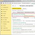 Payroll in UPP 8