Employed schemes on the dumping board. Breadboard - electronic designer for all. Mounting insane feet with rods
Hello everyone. Today we will talk about the covertuous male Plate or O. breadboard.as they call her bourgeois. This fee, if you can express it, is included in the list. mandatory instrumentsWhat should be an electron-made (whether it is a young brainchik, which only makes the first uncertain tags or a buried and who who who who who who who who who who who who who who who who who who who who who had everded life).
Knowledge of what bold fees are, how and where such tools use, will help you when developing and commissioning own projects Various electronic homemade.
The first boards looked like this:

Based on attached metal rackswhich were later fixed (simply wounded) wires and contact conclusions of elements.
It is good that technical progress does not stand still - because thanks to its influence we can use these wonderful tools.

In contrast, the invading dumping board can be set this (they are significantly cheaper and manufactured based on the necessary parameters).


However, when installing on an invoking card, you will not need a soldering iron / solder. In addition, you will avoid difficulties associated with the split parts on the board surface.
Rule good toneYes, and common sense, there has always been prototyping electronic circuits. It is important to know how the device will behave with certain defined parameters, Before assembling the finished device.

In addition, using an invaric board, you can check the performance of new components and radio components.
Consider the structure of the covert

Let's look at the drawing of the board. It consists of rows metal plates (rails).
The rail in turn consists of clamps, in which the installation of the "legs" of radio components occurs. All 5 holes in the row are connected together.


Now reverse our gaze to two vertical / horizontal bands (depending in what position is it), which are located separately (along the edges) are the power plates. All sockets of one long plate are connected to each other.
Central groove isolates the side of the board. The width of this band is fixed by the standard. It allows you to install DIP chips in such a way that each output is installed in a separate rail and allows you to connect up to 4 external conclusions.

Boards caused alphabetic and digital sequences. The designations data help navigate the components to eliminate the erroneous connection (which may end the inoperability of the circuit or failure of individual parts).
Also release fees that are manufactured on separate supports with special clamping terminals. They are used to connect the power supply to the board.

If you drew attention on some boards there are special grooves and protrusions (they are located on the sides). With their help, you can combine fees and create working surface of any size.

Also on some boards on the back of the self-adhesive basis.
The figure shows the "Washing" board from Arduino.

If you got a board with terminals in your hands, you need to connect them to the lines on the batch with the help of conductors (jumpers). Terminals are not associated with any line. To connect the wire to the terminal, remove the plastic cap and place the end of the wire into the hole. Install the cap back. Usually used two terminals: for food and for Earth.
Now it remains for small, connect the external power source. This can be done with:
- jumpers;
- "Crocodiles" or ordinary wires;

- power stabilizer modules, which are produced under inchespace.

Thanks for attention. The continuation should be 🙂
If the first part of the article focuses on the overview of the bias and the description of their device, then now consider some useful subtleties and nonsions that you need to know when working with such dumping fees.
If the Instructions of the Inpaid Macate Fee says that the diameter of the wire inserted into contacts is 0.4 - 0.7 mm, then you should not try to insert the findings of parts that the thickness of the specified value. This will bring to weaken and wear contacts. If there is a need to apply such parts, then it is better to roll to the thick conclusions of the wire of the specified diameter, or simply wrap. Naturally, the wire must be without isolation.
Clearchy dump trucks are sold in two configurations: with wires - jumpers and without them. In the first version, the fee is obtained somewhat more expensive, but not at all troubles, if you managed to buy a single fee, - you can always adapt anything.
The switching wires, of course, are sold separately, but if there is no desire or to buy them, it is quite suitable for the KSVV 4 * 0.4 Wire, used for mounting.
Such a wire contains 4 insulated veins with a diameter of just 0.4 mm. Isolation from the wire is easily removed by rake or knife, and the residential veins do not have a varnish coating.
In case of the need to make the complex device, its individual functionally completed parts are better to collect on separate dumping fees. small sizes, after which from the obtained nodes collect the whole design.
Sometimes it happens that one device is not yet collected, but for some reason it is necessary to urgently assemble another, completely new. And here it begins! It is necessary to disassemble the collected, not yet debt scheme, which, then, may have to be collected again. But the only irreplaceable resource is the time that is lost on these meaningless assemblies - disassembly. Therefore, it is better not to notice, but to acquire several dumping boards, it will go faster.
 We should not forget that the bold fees are designed for low-current equipment - and. Therefore, in no case in any case, it is unacceptable to supply network voltage on them - 220 V. It can lead to overheating of contacts and a breakdown of isolation, and what will happen after that everything is probably known.
But even in transistors and chips, a short circuit may occur, which will cause overheating of these elements, will lead to the heating of contacts and melting the plastic base of the board. Therefore, when you first turn on the circuit, it is desirable to measure the current consumed or at least check the temperature of all elements with a finger.
General rule, not only for dumping boards. First, components are installed not exposed to static electricity:, and.
In addition to the details, connective wires are installed on the dumping board. Connecting wires are better installed with tweezers or small pliers. With these tools to conduct and disassemble the wires.
As in all such cases, check the fee on the correct installation, on the absence of short circuits or non-contacts. Unused conclusions by chips do not leave "hanging in the air", and connect either to a common wire or to the power bus. Free inputs will lead to the appearance of such elements, simply no interference, which will be distributed throughout the circuit and its adjustment will be much more problematic.
 Probably, it will have to be noted here that the dumping fees have a large fitting capacity due to long connecting wires, as well as many contacts. Therefore, too high-frequency schemes on such fees will work badly, and may not be completely.
To avoid the influence of long conductors, it is desirable to shut down the power to the microcircuit with ceramic capacitors of a small capacity, as is done on printed circuit boards.
Checking the correct installation, you can use the "oak" TTL chips, which are practically not sensitive to statics. You can, of course, do without them, but it is not very convenient to overtake the cream of the multimeter into the holes on the board, it is more convenient to touch the legs of the chip. After completing the inspection and eliminating the inaccuracies, "training" chips should be replaced by real.
When using the CMOS structure chips to protect against statics, the use of antistatic grounding bracelets is very desirable. If there are no such available, you can recommend the use of a wire washcloth for washing pan. Such a mustache has the shape of a ring where you can push your hand. With the help of a flexible wire through a resistor resistance to no more than 1m connected to grounding.
After checking the circuit, you can insert the CMOS microcircuits mentioned in the fee. When setting up the scheme, replacing parts, or making changes, the protective antistatic bracelet is better not to remove.
Macateboards can be collected for any device. They are popular with novice electropheresters and experienced masters. They are collected with soldering and without soldering. The first durable and can be used as the main fee, and the second are more comfortable in assembly due to the exclusion of soldering works.
To start the production of any product, it is necessary to make it layout, and then, appreciating the productivity of the product and its other parameters, proceed to the release of the series. In this case, you save money and time. But the prototypes are made not only in production, they are also widely used in electronics and, first of all, this is due to the release of dummy cards.
Suppose you are going to make a new electronic device. Previously, the prototype of the bold fee was the appearance of a rectangle from the cardboard, in which the holes were made and the radio elements connecting between themselves were inserted there, and then its work was checked. If the functioning of the device occurred normally, the production of the main board began using the appropriate materials. Now the task is somewhat simplifiable - the market is actively sold by bias with already prepared holes and tracks, which can be found in specialized stores, for example, in this http://makerplus.ru/, where you can choose the appropriate option.
What bold fees are
Macateboards are made without soldering and soldering. The design without soldering is a plastic housing with numerous holes with contact connectors. Details are mounted in them. Holes are designed for wires with a diameter of 0, 7 mm. The distance between them is 2, 54 mm, this is enough to install the transistor and other elements.
Power tracks are designated blue and red lines. The number of points for connectors may vary from 100 to 2500 pieces. The principle of working with such a board is simple. You mounted B. opened holes electronic elements And connect them with ordinary wires, or buy specially prepared wire jumpers. If the scheme is collected incorrectly, then you disassemble it and install it again.
Soldering
This board differs from the above option that the elements installed in the housing can be soldered. In this case, you can use it not only as a layout, but also as a real product. True, then the fee will have several large sizes. In addition, soldering structures have a lower price.
Boards with soldering, which, by the way, can be purchased on the page of the online store http://makerplus.ru/category/breadboard, have holes for wires with a diameter of up to 0.9 mm and are located in one-inch increment (2, 54mm). On the one hand, the design is located straight insulated foil lines, and the radio elements and jumpers are installed on the other.
- Immediately cut down the fee to of the desired size. For this, conventional scissors, cutter, hacksawa are suitable. You can even just break her over holes, but then checking the edges.
- If you are not going to use the board right now, then do not touch the places with the foil once again. Hands can be wet, which will lead to corrosion of the surface and deterioration of contact.
- If oxides or pollution take place, clean them with zero emery paper or ordinary eraser.
- Radio elements are installed from the side where there are no strips from foil. The conclusions are populated into the holes and searched from the reverse side.
- Blue color conductive tracks denotes "minus" schemes, red "plus", and green is used at their discretion. The tracks are marked with the same side where the foil is located.
- The most important positioning of parts occurs in a vertical position, since in this case the error will lead to an incorrectly assembled chain.
Consider that the bikes of both types can have a groove on the sides. It is necessary for those who collect big deviceconsisting of several modules. The grooves allow you to collect one large fee of several small.
Let's look at the device and the purpose of inconceptuous dump trucks. What is their advantage over other types of assembly, and how to work with them, as well as what schemes you can quickly assemble a newcomer on them.
Prehistory.
The first problem with which the radio amateler faces is not even the lack of theoretical knowledge, but the absence of funds and knowledge of the methods of installation electronic devices. If you do not know how this or that part works, it does not prevent you from connecting it according to the electrical principal scheme, but to clearly and qualitatively assemble the scheme you need a circuit board. Most often they are made by the method of Lout, but there is not a laser printer. Our fathers and grandfathers drew fees with manually lacquer nail or paint, and then they etched them.

Here, the novice overtakes the second problem - the lack of reagents for etching. Yes, of course, the chlorine iron is sold in every store of radio-electronic components, but at first and so you need to purchase a lot of things and explore that it is simply difficult to pay attention to the attention of the technology of etching boards from foil textolite. Yes, and not only newcomers, but also experienced radio amateurs sometimes makes no sense to strive the fee and spend funds on the flawed product on the stages of its adjustment.

To avoid problems with the search for chlorine iron, textolite, printer and not get from his wife (mothers) for unauthorized use of the iron, you can practic in the installation of electronic devices on inconceptuous dumping fees.
What is an inconvenient baker?
As can be seen from the name, this is such a board on which you can collect the layout of the device without the use of the soldering iron. The mock - so it is called in the people - in the stores there are different sizes And the models are somewhat different by layout, but the principle of operation and the internal device are the same.
The dumping board consists of a plastic ABS housing, in which the connectors are located, which resemble the dual metal tires between which the conductor is clamping. On the front part of the hole housing, numbered and marked, they can insert wires, the legs of the chip, transistors and other radio components in the housings with the outputs. Take a look at the picture below, I finished it all.

On the discussed circuit board, the extreme two columns of the holes with each side were combined by vertically by common tires, from which the power supply of the power supply and a minus (total bus) usually form the tire of the plus contact. Usually designated red and blue stripes on the edge of the board plus and minus, respectively.
The middle part of the board is divided into two parts, each of the parts are arranged on the five holes in the row on this particular board. The figure shows a schematic connection of the holes (black solid lines).

The internal structure of the board is shown in the figure below. Dual tires clamp conductions as illustrated. Internal connections are indicated by bold lines.

Such fees in the English-speaking environment are called Breadboard for this name you can find it on Aliexpress and similar online stores.
How to work with it?
Just into the holes insert the legs of the electronic components, connecting the parts by horizontal lines among themselves, and with extreme vertical feeds. If you need a jumper often use special with thin plugs on the end, you can find them on the name "DuPont jumpers" or jumpers for Arduino, by the way, you can also insert it into such a laypete and collect your projects.

If you have not enough sizes of one dummy card you can combine a few, it like puzzles are inserted into each other, pay attention to the first picture in the article scheme assembled on two connected boards. On one of them there is a spike, and on the other notch, bevelled from the outer part to the board body so that the design does not fall apart.

Assembly simple schemes on a dumping board
A novice radio amateur is important to quickly collect a scheme to make sure the performance and understand how it works. Let's look at what different schemes look on the dumping board.

The diagram of a symmetric multivibrator is advised as the first to many newcomers, it allows you to learn how to connect the parts sequentially and in parallel, as well as to determine the base of transistors. It can be collected by mounted installation or dilute the printed circuit board, but it requires soldering, and mounted installation despite its simplicity is actually very complex for beginners and fraught with closures or poor contact.
See how simple it looks like an invisidious dummy.

By the way, pay attention here did not use DuPont jumpers. In general, they can not be found in radio markets, and especially in the stores of small cities. Instead, you can use veins from the Internet cable ( Twisted para) They are in isolation, but lived not covered with varnish, which allows you to quickly bargain the end of the cable, removing a small layer of insulation and insert in the connector on the board.
You can connect the details as you like, just to provide the desired chain, here the same scheme, but is collected slightly differently.

By the way, you can use the card marking to describe the connections, the columns are denoted by letters, and the lines are numbers.

For your designs there are such power supplies, there are plugs that are mounted in an invoking board connecting to the "+" and "-" tires. It is convenient, it has a switch and a linear low-noise voltage stabilizer. In general, you will not be difficult to dissolve this fee yourself and collect it.

That's how, for example, to check it. The picture shows a more "advanced" version of the printed circuit board with clamping terminals for connecting the power supply. Anode of the LED is connected to the power plus (red bus) and the cathode on horizontal tire Working area, where and is connected to a current-limitary resistor.
Power supply on a L7805 linear stabilizer, or any other L78xx series chip, where the XX is the voltage you need.

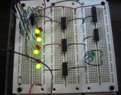
The collected compound scheme on logic. Correct name Such a scheme is a pulse generator on logical elements of type 2I - not. First, read the electrical principal scheme.

Domestic K155L3 is suitable as a logical chip, or foreign type 74hc00. The elements R and C set the operating frequency. Here is its implementation on the board without soldering.

On the right, the white piece of paper is a bouzzer. It can be replaced by LED if you reduce the frequency.
The more resistance or capacity - the less frequency.
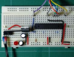
But it looks like typical project Arduinshka at the testing and development stage (and sometimes in the ultimately, depends on how lazy it is).

Actually B. lately The popularity of "Bradbordov" has increased significantly. They allow you to quickly collect schemes and check their performance, as well as use as a connectivity when flashing chips in the DIP case, and in other cases, if there is an adapter.
Restrictions of invading dummy
Despite his simplicity and obvious advantages Before soldering, covertless layers have a number of flaws. The fact is that not all chains work normally in such a design, let's consider in more detail.
Overfellular dummy cards are not recommended to collect powerful converters, and especially impulse schemes. The first will not work normally because of the current bandwidth contact tracks. It is not necessary to climb more than 1-2 amps for currents, although there are and reports on which include 5 amps, make the conclusions themselves and experiment.
electrical safety
Don't forget that high voltage life threatening. Maketing of devices of working, for example, from 220 V is prohibited categorically. Although conclusions are closed plastic panelBut a bunch of conductors and jumpers can lead to a random closure or electric shock!
Conclusion

The worsening fee is suitable for simple schemes, analog circuits that do not prevent high requirements for electrical connections and accuracy, automation and digital circuits that do not work on high speeds (Gighellians and dozens of megahertz are already too). At the same time, high voltage and currents are dangerous and for such purposes it is better to use mounted installation and printed circuit boardsAt the same time, the newcomer should not be attached to the installation of such chains. Element of beamless dummy plates - the simplest schemes up to a dozen elements and amateur projects on Arduino and other microcontrollers.
All people in the world from Mala are known to know that before creating something, you must first create a layout of this "anything", be it layout of the building, stadium or even a small rural toilet. In electrical engineering, this is called the prototype. The prototype is a working device model. Therefore, experienced electronics, before collecting the device according to the scheme on the Internet, noted by someone who do not understand why, should make sure that this scheme really will work. Therefore, the scheme must be quickly pickled to assemble and make sure of its performance, that is, collect layout. Well, in order to collect it, just need it bread board.
Types of Mackety Plasteps
Thick cardboard
A long time ago, when you still did not even be in the plans, our grandfathers, and maybe grandmothers, you never know :-), used thick cardboard.This is the fastest and cheapest way to check schemas. The cardboard cut holes under the conclusions of radio elements and on the other hand they were connected with the help of wires and other elements, if they did not fit on the front side. It looked like something like something:
A - type facial side, in the reverse side.
Everything is good, but I had to solder conclusions, to watch anywhere else closed, and so far I have "you," this scheme can even be lost in the lacquer :-). Yes, and not beautiful somehow.
Homemade dumping fees
These times, I still found on a radio compartment. Then we made the bold fee themselves. They took a sharp cutter and cut the squares on the foil textolite. Next covered them with the solder.

If necessary somewhere to connect the tracks, we simply made jumpers between the squares of the solder drop. It turned out high quality and beautiful. If it was too lazy to overpass radio elements on a normal-divided fee with tracks, they simply left as it were and used the device.
Disposable dumping fees
Manufacturers Still this is the "chungy" case, or as they say in the economy, the demand gives rise to a sentence. Finished dilated scarves began to appear, and even double-sided for any size and taste.


By the way, they can be found on Ali immediately whole set .
The holes are very conveniently chosen in size by chip conclusions, as well as other radio elements. Therefore, it is very convenient to collect and check the radio electronic device on such dumping fees. Yes, they are inexpensive.

back side Such dummy cards with ready-made devices will look approximately like this:

What are the disadvantages of these dumping boards? It is still better to use them once, since with a reusable use, they can fly into stakes, which will lead to its unsuitability.
Chippeatties
Progress steps with his confident step in our world, and here it appeared on the market chimperic dumping fees.

They stand a little more expensive than simple disposable bold fees, but to be honest, it is worth it.
They are very convenient in terms of setting parts, as well as their connection among themselves. In such dumping fees, there are no more than 0.7 mm wires and not less than 0.4 mm in diameter. To find out which holes and paths are called with each other, check the whole thing. For design large schemes (Suddenly you will develop any administrative collider control unit) You can add the same bias in principle. For this there are special ears. One movement, and the bold fee will be a bit more.


Well, what kind of bakery can be without connecting wires? Connecting wires, or jumpers ( from English - Jump), we need to connect radio components on the dumping board itself.

A little later, I bought such jumpers with Aliexpress. They are much more convenient than wire:
.JPG)
Here everything is simple, take jumper and insert it with a light movement of your hand


Let's collect the simplest Scheme of turning on the LED across the button on the Male

That's how it will look

Test 5 volts on the power supply and click on the button. The LED lights up bright green. So the scheme is workable, and we can use it at your discretion.

Conclusion
Chimunical Macateboards conquer the world. Any scheme for them can be collected and disassemble in a matter of minutes. After assembling and checking the scheme on the dummy board, you can safely begin to assemble in its pure form. I think every respected electrical machine should have such a damp. But keep in mind the schemes with a lot of current in the chain is still not to check on it, as the contacts of the cakes can simply burn out - the law of Joule-Lenza. Good luck to you in the design and design of radio-electronic devices!
Where to buy a batch fee
Makeup with flexible jumpers and even with a finished 5 volt power supply can be immediately bought at Aliexpress. Choose Your taste and color!

If you do not want, it will be easiest to buy a one-time discount board and collect the finished device on it:
 Why you can not give icons
 Is it possible to give icons as a gift: Signs, the opinion of the Church
 A year ago left her husband, and now I do not know what to do