Which sign indicates the combined scheme. Conditional graphic designations of electrical and electronic circuit elements. Rules for performing location schemes
GOST 2.702-2011
Group T52.
Interstate standard
Unified system of design documentation
Electric circuits
Unified System of Design Documentation. Rules for Presentation of Electric Schemes
ISS 01.100
OKSTA 0002.
Date of introduction 2012-01-01
Preface
Objectives, basic principles and the main procedure for working on interstate standardization GOST 1.0-92 "Interstate standardization system. Basic provisions" and GOST 1.2-2009 "Interstate standardization system. Standards interstate, rules and recommendations on interstate standardization. Development rules, adoption, Applications, updates and cancellation "
Information about standard
1 Developed by the Federal State Unitary Enterprise "All-Russian Research Institute of Standardization and Certification in Mechanical Engineering" (FSUE "VNIINMASH"), Autonomous Non-Profit Organization "Research Center CALS-Technologies" Applied Logistics "(ANO NIC CALS-technologies" Applied Logistics " )
2 introduced by the Federal Agency for Technical Regulation and Metrology
3 Adopted by the Interstate Council for Standardization, Metrology and Certification (Protocol of May 12, 2011 N 39)
For the adoption of the standard voted:
Short name of the country on MK (ISO 3166) 004-97 | Abbreviated name of the National Standardization Authority |
|
Azerbaijan | Azstandard |
|
Ministry of Economy of the Republic of Armenia |
||
Belarus | Gosstandart of the Republic of Belarus |
|
Kazakhstan | Gosstandart of the Republic of Kazakhstan |
|
Kyrgyzstan. | Kyrgyzstandart |
|
Moldova Standard |
||
the Russian Federation | Rosstandard. |
|
Tajikistan | Tajikstandard |
|
Uzbekistan | Ustanndart |
|
State StandStandart of Ukraine |
4 by the order of the Federal Agency for Technical Regulation and Metrology of August 3, 2011 N 211-ST Interstate Standard GOST 2.702-2011 was enacted as the National Standard of the Russian Federation from January 1, 2012
5 Instead of GOST 2.702-75
Information on the introduction of (termination) of this Standard is published in the National Standards Index.
Information about the changes to this standard is published in the "National Standards" index, and the text of the changes - in the information signs "National Standards". In case of revision or cancellation of this standard, relevant information will be published in the information indicator "National Standards"
1 area of \u200b\u200buse
1 area of \u200b\u200buse
This standard applies to electrical schemes of products of all industries, as well as electrical schemes of energy facilities and establishes rules for their implementation.
Based on this standard, it is allowed, if necessary, develop standards for the implementation of electrical schemes of products of specific types of equipment, taking into account their specifics.
2 Regulatory references
This standard uses regulatory references to the following interstate standards:
GOST 2.051-2006 Unified system of design documentation. Electronic documents. General provisions
GOST 2.053-2006 Unified system of design documentation. Electronic structure of the product. General provisions
GOST 2.104-2006 Unified system of design documentation. Main inscriptions
GOST 2.701-2008 Unified system of design documentation. Schemes. Types and types. General requirements for implementation
GOST 2.709-89 Unified system of design documentation. Designations Conditional wires and contact compounds of electrical elements, equipment and sections of chains in electrical circuits
GOST 2.710-81 Unified system of design documentation. Designations of alphanumeric in electrical circuits
GOST 2.721-74 Unified system of design documentation. Conditional graphic designations in schemes. General application
GOST 2.755-87 Unified system of design documentation. Designations conditional graphic in electrical circuits. Commutation and contact connections
Note - When using this standard, it is advisable to verify the action of reference standards in the public information system - on the official website of the Federal Agency for Technical Regulation and Metrology on the Internet or on the National Standards Annually published information indicator, which is published as of January 1 of the current year , and according to the corresponding monthly information indicators published in the current year. If the reference standard is replaced (changed), then when using this standard should be guided by replacing (modified) standard. If the reference standard is canceled without replacement, the position in which the reference is given to it is applied in a portion that does not affect this link.
3 Terms, Definitions and Reducing
3.1 This standard applies the following terms with the corresponding definitions:
3.2 This standard applies the following abbreviations:
ECCD - a unified system of design documentation;
Hugo - conditional graphics symbols;
ECI - electronic structure of the product;
CD - design document.
4 Basic provisions
4.1 Electric circuit - a document containing in the form of conventional images or designations, the components of the product acting using electrical energy and their relationship.
4.2 Electrical circuits can be made as paper and (or) electronic CD.
4.3 General requirements for implementation, types and types of schemes - according to GOST 2.701.
Rules for constructing conditional alphanumeric designations of elements, devices and functional groups in electrical circuits - according to GOST 2.710.
Note - If the electrical circuit is performed as an electronic CD, it is necessary to additionally be guided by GOST 2.051.
4.4 Electrical circuits Depending on the main purpose, divided into the following types:
- structural;
- functional;
- principled;
- compounds;
- connections;
- general;
- location.
4.5 It is allowed to put the explanatory inscriptions, diagrams or tables on the diagram defining the sequence of processes in time, as well as specify the parameters in the characteristic points (the values \u200b\u200bof currents, stresses, shapes and the values \u200b\u200bof pulses, mathematical dependencies, etc.).
5 rules for performing schemes
5.1 Rules for the implementation of structural schemes
5.1.1 The structural diagram depicts all the main functional parts of the product (elements, devices and functional groups) and the main relationship between them.
5.1.2 Functional parts The diagram is depicted in the form of rectangles or hugo.
5.1.3 The graphic construct of the scheme should provide the best idea of \u200b\u200bthe sequence of interaction between functional parts in the product.
On lines of relationships, it is recommended to designate the direction of the processes occurring in the product.
5.1.4 The scheme should indicate the names of each functional part of the product, if a rectangle is applied to its designation.
The diagram allows you to specify the type of element (device) and (or) designation of the document (the main design document, standard, technical conditions), on the basis of which this element (device) is applied.
When the functional parts are depicted in the form of rectangles of the names, types and designations are recommended to fit into the rectangles.
5.1.5 With a large number of functional parts, it is allowed instead of the names, types and designations to lift the ordinal numbers to the right of the image or above it, as a rule, from top to bottom in the direction from left to right. In this case, the names, types and notation are indicated in the table placed on the schema field.
5.2 Rules for performing functional schemes
5.2.1 The functional diagram depicts the functional parts of the product (elements, devices and function groups) involved in the process illustrated by the circuit and the connection between these parts.
5.2.2 Functional parts and interrelations between them in the diagram are depicted in the form of hugo installed in ECC standards. Separate functional parts are allowed to portray in the form of rectangles.
5.2.3 The graphical construction of the scheme should give the most visual representation of the sequence of processes illustrated by the scheme.
5.2.4 Elements and devices are depicted in the schemes in a combined or separated method.
5.2.5 With the combined method, the components of the elements or devices are depicted in the diagram in close proximity to each other.
5.2.6 With a separated method, composite parts of elements and devices or individual elements of devices are depicted in the diagram in different places in such a way that individual chains of the product are depicted most clearly.
Discussion is allowed to depict all and individual elements or devices.
When performing diagrams, it is recommended to use the line method. In this case, the hugo elements or their constituent parts included in one chain are depicted successively by each other in a straight line, and individual chains are near, forming parallel (horizontal or vertical) strings.
When performing a diagram, the strings of the Arabic figures are allowed to numbered (see Figure 1).
Picture 1
5.2.7 In the image of elements or devices, the separated method is allowed on the free field of the scheme to place the hugo elements or devices performed by the combined method. In this case, the elements or devices used in the product are partially depicted fully indicating the used and unused parts or elements (for example, all contacts of the multi-contact relay).
Conclusions (Contacts) of unused elements (parts) are depicted in short than conclusions (contacts) of the elements used (parts) (see Figure 2).
Figure 2.
5.2.8 Schemes are performed in a multi-cable or unicineal image.
5.2.9 With a multi-line image, each chain is depicted by a separate line, and the elements contained in these chains are separate hug (see Figure 3 but).
but - Multicore image | b. - Single Picture |
Figure 3.
5.2.10 With a single-line image of a chain that perform identical functions are depicted by one line, and the same elements of these chains are one hug (see Figure 3 b.).
5.2.11, if necessary, the scheme denotes electrical chains. These designations must comply with the requirements of GOST 2.709.
5.2.12 When an image on the same diagram of various functional circuits is allowed to distinguish between their thickness thickness. In one scheme, it is recommended to use no more than three dimensions of the lines in thickness. If necessary, the corresponding explanations are placed on the schema field.
5.2.13 To simplify the scheme, it is allowed to merge several electrically related lines of interconnection into a group relationship line, but when approaching contacts (elements), each line of relationships are depicted by a separate line.
When merging the interconnection lines, each line is tagged at the fusion site, and if necessary, both on both ends with conventions (numbers, letters or a combination of letters and numbers) or notation adopted for electrical circuits (see 5.2.11).
Line designations are affixed in accordance with the requirements given in GOST 2.721.
The lines of electrical relationships drained in the group of group relationships, as a rule, should not have branches, i.e. Any conditional number should meet on a group relationship line twice. If you need to branch, their number indicates after the order number of the line through a fractional line (see Figure 4).
Figure 4.
5.2.14 It is allowed if it does not complicate the scheme, separately depicted parts of the elements connect the line of mechanical interconnection indicating their belonging to one element.
In this case, the positional designations of the elements are affixed by one or both of the ends of the mechanical relationship.
5.2.15 The scheme should indicate:
- for each functional group - the designation assigned to it on the schematic diagram, and (or) its name; If the functional group is depicted in the form of hugo, then its name does not indicate;
- for each device depicted in the form of a rectangle - a positional designation assigned to it on a schematic diagram, its name and type and (or) designation of the document (the main design document, standard, technical conditions), on the basis of which this device was applied;
- for each device depicted in the form of hugo, is a positional designation assigned to it on a schematic diagram, its type and (or) document designation;
- For each element, a positional designation assigned to it on a schematic diagram, and (or) its type.
The designation of the document, on the basis of which the device was applied, and the type of item is allowed not to indicate.
Names, types and designations are recommended to fit into rectangles.
5.3 Rules for implementing the schematic diagrams
5.3.1 The schematic diagram depicts all electrical elements or devices necessary for carrying out and controlling the product of installed electrical processes, all electrical relationships between them, as well as electrical elements (connectors, clamps, etc.), which end the input and output chains.
5.3.2 The scheme is allowed to portray the connecting and mounting elements installed in the product according to constructive considerations.
5.3.3 Schemes are performed for products located in a disconnected position.
In technical cases, individual elements of the scheme are allowed to depict in the selected operating position with an indication of the mode circuit field for which these elements are depicted.
5.3.4 Elements and devices that are installed in ESCD standards are depicted in the scheme in the form of these hugo.
Note - If the hugo standards are not established, the developer performs the coo in the field fields and gives explanation.
5.3.5 The elements or devices used in the product are partially allowed to portray the scheme not completely, limited by the image of only parts used or elements.
5.3.6 When implementing the concept, it is allowed to use the provisions specified in 5.2.4-5.2.14.
5.3.7 Each element and (or) a device having an independent principal scheme and considered as an element included in the product and shown in the diagram must have a designation (positional designation) in accordance with GOST 2.710.
Devices that do not have independent schematic diagrams and functional groups are recommended to assign designations in accordance with GOST 2.710.
5.3.8 Positional designations Elements (devices) should be assigned within the product (installation).
5.3.9 The sequence numbers of the elements (devices) should be assigned, starting from the unit, within the group of elements (devices), which in the diagram is assigned the same letter positional designation, for example,, etc. ,,,, etc.
5.3.10 The sequence numbers should be assigned in accordance with the sequence of the location of the elements or devices on the diagram from top to bottom in the direction from left to right.
If necessary, it is allowed to change the sequence of assignment of sequence numbers depending on the placement of the elements in the product, the direction of passage of signals or the functional sequence of the process.
When making changes to the scheme, the sequence of assignment of sequence numbers can be changed.
5.3.11 The positional designations are affixed in the scheme next to the hugo elements and (or) devices on the right side or above them.
It is allowed to be positioned in the horn rectangle.
5.3.12 On the product scheme, which includes devices that do not have independent schematic diagrams, it is allowed to assign items to the elements within each device.
If the product includes several identical devices, then the positional designations should be assigned to the elements within these devices.
The sequence numbers elements should be assigned according to the rules set in 5.3.9.
Elements that are not included in the device, the positional notation is assigned, starting from the unit, according to the rules set in 5.3.8-5.3.10.
5.3.13 On the product scheme, which includes functional groups, the positional designations are assigned by the rules established in 5.3.8-5.3.10, while first assigning the positional designations to the elements that are not included in the functional groups, and then elements incoming in functional groups.
In the presence of several identical functional groups, the positional designations of the elements assigned to one of these groups should be repeated in all subsequent groups.
The designation of the functional group assigned in accordance with GOST 2.710 is indicated near the image of the functional group (from above or right).
5.3.14 As an image on the element or device diagram, the positional designation of the element or device is affixed near each composite part (see Figure 5).
Combined way image device | Designed way image device |
Figure 5.
If the scheme field is divided into zones or circuit, it is made in a lower case method, then to the right of the positional designation or under the positional designation of each composite part of the element or device is allowed to be specified in the probes of the zones or rows numbers in which all other components of this element or device are depicted (cm . Figure 6).
Figure 6.
It is allowed when an image of each component of an element or device is described on the element or device diagram of each component of the element or device, but with an indication of the conclusions (contacts) for each part of the conclusions (contacts).
5.3.15 In the image of individual elements of devices in different places, the positional designation of the device should be included in the composition of the positional designations of these elements, for example \u003d A3-C5 - C5 condenser included in the A3 device.
5.3.16 With a separated method of an image of a functional group (if necessary and combined method), the positional group should be included in the positional designation of the elements included in this group, for example, T1-C5 - C5 condenser included in the T1 functional group.
5.3.17 With a single-line image of about one HTO, replacing several hugo elements or devices, indicate the positional notation of all these elements or devices.
If the same elements or devices are not in all circuits depicted one-centers, then to the right of the positional notation or under it in square brackets indicate the designations of the chains in which these elements or devices are located (see Figure 3).
5.3.18 On the basis of the Schematic diagram, all the elements and devices included in the product and shown in the diagram should be unambiguously defined.
Data on items should be recorded in the list of elements, designed as a table according to GOST 2.701. In this case, the connection of the list with hugo elements should be carried out through the positional notation.
For electronic documents, the list of elements is issued by a separate document.
When you turn on the elements of the circuit in ECI (GOST 2.053), the list of elements decorated according to GOST 2.701 is recommended to receive from it in the form of a report.
It is allowed in some cases established by standards, all the information about the elements is placed near the Hugo.
5.3.19 With a difficult entry, for example, when a device that does not have an independent concept is one or more devices that have independent scores, and (or) functional groups, or if one or more devices are included in the function group, etc. D., then in the list of elements in the column "name" before the name of devices that do not have independent schematic diagrams and functional groups are allowed to be lifted by ordinal numbers (i.e., like the designation of sections, subsections, etc.) within the entire product scheme (see Figure 7). Functional nodes or devices (including those performed on a separate board) are isolated by dashing lines. If a positional designation of the device or the designation of the function group is enabled on the diagram to a positional designation of the element, then in the list of items in the column "pos." Designation "indicate the positional designation of the element without the positional designation of the device or the designation of the functional group.
Figure 7.
5.3.20 When specifying the coo ratings of resistors and capacitors (see Figure 8), it is allowed to use a simplified method of designation of units of values:
- For resistors:
from 0 to 999 ohms - without specifying units,
from 1 · 10 to 999 · 10 ohms - in kiloma with the designation unit of the values \u200b\u200bof the lowercase letter K,
from 1 · 10 to 999 · 10 ohms - in megaoms with the designation of a unit of quantities of the capital letter M,
over 1 · 10 Ohms - in gigamas with the designation unit of the values \u200b\u200bof the capital letter G;
- for capacitors:
from 0 to 9999 · 12 f * - in picoparades without specifying a unit of quantities,
________________
* The text of the document corresponds to the original. - Note database manufacturer.
from 1 · 10 to 9999 · 10 Ф - in micropraids with the designation of a unit of the values \u200b\u200bof the LC MK.
Figure 8.
5.3.21 The diagram should indicate the designations of outputs (contacts) of elements (devices) applied to the product or installed in their documentation.
If in the design of the element (device) and in its documentation, the conclusions (contacts) are not specified, then it is allowed to conditionally assign them the designations in the diagram, repeating them later in the relevant design documents.
With the conditional assignment of the designations of the outputs (contacts) on the schema field, the corresponding explanation is placed.
When an image of several identical elements (devices) of the conclusions (contacts), it is allowed to be indicated on one of them.
With a separated method of an image of the same elements (devices) of the conclusions (contacts), indicate each component of the element (device).
To distingvia on the indication scheme of the conclusions (contacts) from other designations (chain designations, etc.), it is allowed to record the designations of the conclusions (contacts) with a qualifying symbol in accordance with the requirements of GOST 2.710.
5.3.22 When an element or device is image, an explanatory inscription is placed around one component of the product or on the diagram field near the image of the element or device performed by the combined method.
5.3.23 The scheme is recommended to indicate the characteristics of the input and output chains of the product (frequency, voltage, current strength, resistance, inductance, etc.), as well as the parameters to be measured on control contacts, nests, etc.
If you cannot specify the characteristics or parameters of the input and output chains of the product, it is recommended to indicate the name of the chains or controlled values.
5.3.24 If the product is obviously designed for operation only in a specific product (installation), then the diagram allows you to specify the addresses of external connections of the input and output chains of this product. The address must provide unambiguous attachment, for example, if the output contact of the product must be connected to the fifth pin of the third device connector, the address must be recorded as follows: \u003d 3: 5.
It is allowed to specify the address in general, if the connection is provided, for example "device A".
5.3.25 Characteristics of the input and output chains of the product, as well as the addresses of their external connections, it is recommended to record in the tables placed in return in return of the input and output elements - connectors, boards, etc. (see Figure 9).
Figure 9.
Above the table is allowed to indicate the contact of the contact - socket or pin.
Tables are allowed to be executed by the method.
The order of the contacts in the table is determined by the convenience of constructing the scheme.
It is allowed to place tables with chain characteristics if there is an input and output elements in the coherent diagram - connectors, boards, etc. (see Figure 10).
Figure 10.
Similar tables are recommended to be placed on the lines depicting input and output chains and not ending with connector, boards, etc. In this case, the positional designations are not assigned to the tables.
Notes
1 If there are a multiple tables, the table is allowed to bring the table only in one of them.
2 In the absence of characteristics of input and output circuits or addresses of their external connection, the table does not lead graphs with these data.
If necessary, additional graphs are allowed into the table.
3 is allowed to be stailed in the column "CONT" Several serial contact numbers in case they are interconnected. Contact numbers separate comma from each other.
5.3.26 In the image in the multi-contact connector circuits, it is allowed to apply HTOs that do not show individual contacts (GOST 2.755).
Connecting contact connection information indicate in one of the following ways:
- near the image of the connectors, on the free field of the circuit or on the subsequent sheets of the circuit, the tables are placed in which the address of the connection is indicated [Chain designation (see Figure 11 but) and (or) the positional designation of the elements attached to this contact (see Figure 11 b.)].
but - Table placed on a free field of diagram or on subsequent scheme sheets | b. - Table placed near the Connector Image |
Figure 11.
If necessary, the table indicates the characteristics of the chains and addresses of external connections (see Figure 11 but).
If the tables are placed on the field of the circuit or on the subsequent sheets, they are assigned the positional designations of the connectors to which they are composed.
in the column "Cont." - Connector contact number. Contact numbers are recorded in ascending order,
in the column "Address" - the designation of the chain and (or) the positional designation of the elements connected to the contacts,
in the chain column, the chain characteristic,
in the column "External address" - the address of the external connection;
- Connections with connector contacts are depicted with a separated method (see Figure 12).
Figure 12.
Notes
1 points connected by a dowline with a connector indicate connections with the corresponding contacts of this connector.
2 If necessary, the chart characteristics are placed on the free field of the scheme over the continuation of the interconnection lines.
5.3.27 When an image in the element scheme, the parameters of which are selected during adjustment, near the positional designations of these elements on the diagram and in the list of elements are stars (for example *), and the footnote is placed on the field: "* Pick when adjusting."
The list should write the elements whose parameters are closest to the calculated one.
Permissible when selecting the limit values \u200b\u200bof the elements parameters indicate in the list in the "Note" column.
If the parameter selected when adjusting is provided with elements of various types, these items are listed in the technical requirements on the schema field, and the following data indicate in the graph of the list:
in the column "name" - the name of the element and the parameter closest to the calculated;
in the graph "Note" - a reference to the appropriate item of technical requirements and permissible when selecting the limit values \u200b\u200bof the parameters.
5.3.28 If a parallel or serial connection is carried out to obtain a certain value of the parameter (container or resistance of a certain value), then in the list of elements in the "Notes" column indicate the general (total) element parameter (for example, 151 com).
5.3.29 When the device (or devices) is depicted as a rectangle, it is allowed in a rectangle in return for the hoo input and output elements to place the tables with the characteristics of the input and output circuits (see Figure 13), and outside the rectangle is allowed to place the tables with the addresses of external connections (see . Figure 14).
Figure 13.
Figure 14.
If necessary, additional graphs are allowed into the tables.
Each table is assigned a positional designation of the element, which is placed in return.
In the table, instead of the word "Cont." It is allowed to place the conventional graphic designation of the connector (see Figure 14).
On the product diagram in rectangles, depicting devices, it is allowed to place structural or functional diagrams of devices or to completely or partially repeat their concept schemes.
Elements of these devices in the list of items are not recorded.
If there are several identical devices in the product, the device scheme is recommended to be placed on a free field of the product scheme (and not in a rectangle) with an appropriate inscription, for example, the "A1-A4 block diagram", or at the first entry of such a block, to reveal its scheme, and later Denote the similar blocks with rectangles with the corresponding alphabetic designation.
5.3.30 The scheme field is allowed to place indications of brands, sections and colors of wires and cables (stranded wires, electrical cords), which must be made of elements, as well as indications of specific electrical installation requirements of this product.
5.4 Rules for performing connection schemes
5.4.1 On the compound scheme, all devices and elements included in the product, their input and output elements (connectors, boards, clamps, etc.), as well as connections between these devices and elements.
5.4.2 Devices and items in the diagram are depicting:
- devices - in the form of rectangles or simplified external outlines;
- Elements - in the form of hugo, rectangles or simplified external outlines.
When the elements are depicted in the form of rectangles or simplified external outlines, it is allowed inside them to place hugo elements.
Input and output elements are depicted in the form of hugo.
Input and output elements are allowed to depict according to the rules set to 5.3.25, 5.3.26 and 5.3.29.
5.4.3 The location of the graphic designations of devices and elements in the diagram should approximately correspond to the actual placement of elements and devices in the product.
The location of images of input and output elements or outputs inside graphic designations and devices or elements should roughly correspond to their actual placement in the device or item.
It is allowed in the diagram not to reflect the location of devices and elements in the product, if the scheme is performed on several sheets or placement of devices and elements at the site of operation is unknown.
5.4.4 The elements used in the product are partially allowed to be depicted in the diagram not completely, limited by the image of the only parts used.
5.4.5 The scheme near the graphic designations of devices and elements indicate the positional notation assigned to them on the concept.
Around or inside the graphical designation of the device, it is allowed to specify its name, type and (or) designation of the document, on the basis of which the device is applied.
5.4.6 The diagram should indicate the designations of outputs (contacts) of elements (devices), applied to the product or installed in their documentation.
If in the design of the device or element and in its documentation, the designation of the input and output elements (conclusions) are not specified, then it is allowed to conditionally assign them the designations in the diagram, repeating them later in the relevant design documents.
With the conditional assignment of the designations input and output elements (outputs) on the schema field, the corresponding explanation is placed.
As a picture of several identical devices, the conclusions on the diagram are allowed to be indicated on one of them (for example, the cesspillage of electrical pumping devices).
5.4.7 Devices and elements with the same external connections are allowed to depict the diagram with the connection only for one device or item.
5.4.8 Devices with independent connection schemes are allowed to portray on the product circuit without showing the connections of the wires and cores (stranded wires, electrical cords) to the input and output elements.
5.4.9 As an image on the connectors scheme, it is allowed to apply HTOs that do not show individual contacts (GOST 2.755).
In this case, near the connector image, on the schema field or on the subsequent sheets of the circuit, the tables are placed with an indication of the contact connectivity (see Figure 15).
Figure 15.
When placing tables on the field of the circuit or on the subsequent sheets, they are assigned by the positional designations of the connectors, in addition to which they are composed.
It is allowed in the table to enter additional graphs (for example, data of the wire).
If the harness (cable is a stranded wire, the electric cord, the wire group) connects the same connector contacts, then the table is allowed to place around one end of the image of the harness (cable - stranded wire, electric cord, wire groups).
If the contact connection information is provided in the table of connections, then the tables indicating the connection of the contacts in the diagram is allowed not to place.
5.4.10 The scheme of the product inside rectangles or simplified external outlines depicting devices is allowed to portray their structural, functional or conceptual circuits.
5.4.11 In the absence of a product schema, the contents of the compounds are assigned the positional designations of devices, as well as elements that are not included in the conceptual circuits of the components of the product, according to the rules set in 5.3.7-5.3.11, and write them into the list of elements.
5.4.12 On the product connection diagram it is allowed to show external connection products according to the rules set to 5.5.8, 5.5.9.
5.4.13 Wires, wire groups, harnesses and cables (stranded wires, electrical cords) should be shown in the scheme with separate lines. The thickness of the lines depicting wires, harnesses and cables (stranded wires, electrical cords) in the diagrams should be from 0.4 to 1 mm.
To simplify the design of the circuit, it is allowed to twist separate wires or cables (stranded wires, electrical cords), which are in the diagram in one direction, to the total line.
When approaching contacts, each wire and core core (stranded wire, electric cord) are depicted by a separate line.
The lines depicting wires, wire groups, harnesses and cables (stranded wires, electrical cords), not to carry out or turn them near the attachment places, if their image makes it difficult to read the scheme.
In these cases, the scheme near the attachment places (see Figure 16) or in the table on the free field of the circuit (see Figure 17) put information in a volume sufficient to ensure a unambiguous connection.
Figure 16 Figure 17
5.4.14 On the product scheme, which includes multi-contact elements, lines depicting harnesses (cables - stranded wires, electrical cords, wire groups), allowed only before the contour of the graphic designation of the element without showing the connection to the contacts.
Guidelines for connecting wires or cable (stranded wire, electric cord) to contacts in this case, in this case, in one of the following ways:
- Contacts show ends of lines depicting wires or cable veins (stranded wire, electric cord), and indicate their designations. The ends of the lines are directed towards the appropriate harness, cable (stranded wire, electric cord), wire groups (see Figure 18);
- The image of a multi-contact element placed a table with an indication of the connection of the contacts. The table is connected to a linte-tuning with a corresponding harness, a cable (stranded wire, electric cord), a group of wires (see Figure 19).
Figure 18.
Figure 19.
5.4.15 The introductory elements through which the wires pass (a group of wires, harvesters, cables - stranded wires, electrical cords) are depicted in the form of hugo installed in ECCD standards.
The passage insulators, the germins, glands, contacts and holders, sealed in the printed circuit board, are depicted in the form of the Hugo shown in Figure 20.
but - Line depicting wire (wire group, harness, cable - stranded wire, electric cord)
Figure 20.
5.4.16 The diagram should indicate the designations of introductory elements applied to the product.
If the designations of the introductory elements are not specified in the design of the product, it is allowed to conditionally assign them the designations on the diagram of the compounds, repeating them in the appropriate design documentation. In this case, the necessary explanations are placed on the schema field.
5.4.17 Single-core wires, harnesses, cables (stranded wires, electrical cords) must be indicated by sequence numbers within the product.
Wires, harnesses, cables (stranded wires, electrical cords) should be numbered separately. In this case, the wires included in the harness are numbered within the harness, and the cable veins (stranded wire, electrical cord) - within the cable (stranded wire, electric cord).
Notes
1 It is allowed through the numbering of all wires and cables (stranded wires, electrical cords) within the product.
2 It is allowed through the numbering of individual wires, harnesses and cables (stranded wires, electrical cords) within the product. In this case, the wires included in the harness are numbered within the harness, and the cable veins (stranded wire, electrical cord) - within the cable (stranded wire, electric cord).
3 It is allowed not to denote the harnesses, cables (stranded wires, electrical cords) and separate wires, if the product on which the scheme is making will enter the complex and designations of harness, cables (multicore wires, electric cords) and wires will be assigned within the entire complex.
4 It is allowed to assign the designations of wire groups.
5.4.18 If the concept of electrical circuits are assigned to the electrical chains in accordance with GOST 2.709, then all single-core wires, cable veins (stranded wires, electrical cords) and wiring harnesses are assigned the same designations. At the same time, harnesses and cables (stranded wires, electrical cords) are denoted in accordance with the requirements 5.4.17.
5.4.19 In the diagram with the help of alphanumeric (alphanumeric) designation, it is allowed to determine the functional accessory of the wire, harness or cable (stranded wire, electric cord) to a specific complex, room or functional chain.
The letter (alphanumeric) designation is affixed before the designation of each wire, harness, cable (stranded wire, electric cord), separating it with a sign of the hyphen. In this case, the letter (alphanumeric) designation is included in the designation of each wire, harness and cable (stranded wire, electrical cord).
The design in the designation is allowed not to be stailed if it does not make an ambiguity in reading the scheme.
If all wires, harnesses, cables (stranded wires, electrical cords) shown in the diagram, belong to one complex, room or functional chain, then the letter (alphanumeric) designation is not affixed, and the corresponding explanation is placed on the field.
5.4.20 The number of wires and cable cables (stranded wires, electrical cords) on the diagram is affixed, as a rule, near both ends of images.
The numbers of cables (stranded wires, electrical cords) are lined in circles placed in the breaks of images of cables (stranded wires, electric cords) near the branch locations.
The harness numbers are affixed on the shelves of lines-calls near the branching points of the wires.
Rooms of wire groups are affixed near lines.
Notes
1 With the designation of cables (stranded wires, electrical cords) in accordance with the requirements of 5.4.19, as well as with a large number of cables (stranded wires, electrical cords), which are in the diagram in one direction, the number of cables (stranded wires, electrical cords) is allowed Laying a line without circumference.
2 When an image on the scheme of wires, harnesses and cables (stranded wires, electrical cords), the large length of the number is made through gaps determined by the convenience of using the circuit.
5.4.21 The scheme should indicate:
- For cables (stranded wires, electrical cords) recorded in the specification as a material - a brand, the amount and cross-section lived and, if necessary, the number of occupied lived. The number of employed veins point in a rectangle placed on the right of the denotation of cable data (stranded wire, electric cord);
- for harnesses, cables and wires manufactured separately, is the designation of the main design document.
The diagram contains the characteristics of the input and output circuits of devices and elements or other source data necessary to select specific wires and cables (stranded wires, electrical cords), if, when developing a circuit of the complex, data on wires and cables (stranded wires, electrical cords) cannot be defined.
The characteristics of the input and output chains are recommended to specify in the form of tables (see 5.3.25) placed instead of the conditional graphic designations of the input and output elements.
5.4.22 Data (brand, section, etc.) On wires and cables (multicore wires, electrical cords) indicate near lines depicting wires and cables (stranded wires, electrical cords).
In this case, it is allowed to designate wires and cables (stranded wires, electric cords) without assign.
When specifying data on the wires and cables (stranded wires, electrical cords) as a conventional designation, these designations are decrypted on the schema field.
The same brand, cross section and other data on all or most wires and cables (stranded wires, electrical cords) is allowed to be specified on the schema field.
5.4.23 If the diagram does not specify the location of the attachments (for example, individual contacts in the connectors image are not shown) or finding the locations of the connections of the wires and the cable (stranded wire, electrical cord), then data on wires, harness and cables (stranded wires, Electrical cords) and addresses of their connections are driven into a table called the "Connection Table". The table of connections should be placed on the first sheet of the circuit or perform in the form of an independent document.
The table of compounds placed on the first sheet of the scheme is, as a rule, above the main inscription. The distance between the table and the main inscription must be at least 12 mm.
The continuation of the connections table is placed on the left of the main inscription, repeating the table head.
The table of compounds in the form of an independent document is performed on A4 format. The main inscription and additional graphs to it are performed according to GOST 2.104 (forms 2 and 2a).
5.4.24 The form of the connection table selects the schema developer depending on the information that must be placed in the diagram (see Figure 21).
Figure 21.
In the columctions of the tables indicate the following data:
in the column "Wire designation" - the designation of a single-core wire, cable veins (stranded wire, electric cord) or a harness wire;
in the graphs "where comes", "where comes" - conditional alphanumeric designations of the connected elements or devices;
in the column "Connections" - conditional alphanumeric designations of the connected elements or devices, separating their comma;
in the column "Wire data":
- for a single-core wire - brand, section and, if necessary, coloring in accordance with the document, on the basis of which it is used;
- for cable (stranded wire, electric cord) recorded in the specification as a material - a brand, a cross section and the amount of live in accordance with the document, on the basis of which the cable is used (stranded wire, electric cord);
in the Count "Note" - additional clarifying data.
Notes
2 The columns are allowed to divide into subgraphs.
5.4.25 When filling out the connection table, follow the following order:
- when performing connections with separate wires, the wires are recorded in the order of increasing the numbers assigned to them;
- When performing connections with wires of harness or cable veins (stranded wires, electrical cords) before recording of the wires of each harness or lived each cable (stranded wire, electric cord), the title is placed, for example: "harness 1" or "ABVGHKHXXXXX.032" ; "Cable 3" or "Cable ABBG.HHXXXXX.042"; "Wire 5". Wires of harness or cable veins (stranded wire, electric cord) are recorded in ascending order of numbers assigned to wires or veins;
- When performing connections with separate wires, wiring harnesses and cables (stranded wires, electrical cords), the compound table first recorded separate wires (without title), and then (with the corresponding headers) wiring harnesses and cables (stranded wires, electrical cords).
If insulating tubes, shielding braids, etc. must be attached to the individual wires, then the corresponding instructions are placed in the "Note" column. It is allowed to place these instructions on the schema field.
Note - When applying the compounds scheme, another recording procedure is allowed only if it is installed in industry standards.
5.4.26 On the diagram of the compounds near both the ends of the lines depicting separate wires, the wires of the harnesses and cable veins (stranded wires, electrical cords) is allowed to specify the address of the connections. In this case, the table of compounds do not constitute. Notation Wires Allowed not to assign.
5.4.27 On the field of the scheme over the main inscription, it is allowed to place the necessary technical directions, for example:
- requirements for the inadmissibility of joint laying of some wires, harnesses and cables (stranded wires, electrical cords);
- minimally allowable distances between wires, harness and cables (stranded wires, electric cords); Data on the specificity of laying and protect wires, harnesses and cables (stranded wires, electric cords), etc.
5.5 Connection schemes
5.5.1 A product, its input and output elements (connectors, clamps, etc.) must be depicted on the connection diagram (connectors, clamps, etc.) and the ends of the wires and cables (stranded wires, electrical cords) of the external installation, which is placed on which the connection data is placed Products [characteristics of external circuits and (or) addresses].
5.5.2 The product in the diagram is depicted as a rectangle, and its input and output elements are in the form of hugo.
It is allowed to portray the product in the form of simplified external outlines. Input and output elements are depicted in this case as simplified external outlines.
5.5.3 Placing images of input and output elements inside the graphic designation of the product should approximately correspond to their actual placement in the product.
5.5.4 The diagram should indicate the positional notation of the input and output elements assigned to them on the product schema.
5.5.5 Introductory elements (for example, glazes, germinats, passage insulators, contacts and holders, soldered in a printed circuit board) through which wires or cables (stranded wires, electrical cords, coaxial cables) are depicted in the scheme according to the rules set in 5.4.15.
5.5.6 The scheme should indicate the designations of the input, output or output elements applied to the product.
If the designations of the input, output and output elements in the design of the product are not specified, then it is allowed to conditionally assign them the designations in the diagram, repeating them in the relevant design documentation. In this case, the necessary explanations are placed on the schema field.
5.5.7 In the scheme near the hugo connectors, to which the wires and cables (stranded wires, electrical cords) are attached, it is allowed to indicate the names of these connectors and (or) designations of documents on the basis of which they are applied.
5.5.8 Wires and cables (stranded wires, electrical cords) must be shown in the diagram of individual lines.
5.5.9 If necessary, the scheme indicates brands, sections, colors of wires, as well as the brand of cables (stranded wires, electric cords), quantity, section and employment.
When specifying stamps, sections and coloring of wires in the form of conventional designations on the schema field decrypt these designations.
5.6 Terms of implementation of general schemes
5.6.1 The general diagram depicts devices and elements included in the complex, as well as wires, harnesses and cables (stranded wires, electrical cords) connecting these devices and elements.
5.6.2 Devices and elements on the diagram are depicted in the form of rectangles. Elements are allowed to depict in the form of hugo or simplified external outlines, and devices in the form of simplified external outlines.
The arrangement of the graphic designations of devices and elements in the diagram should roughly correspond to the actual placement of elements and devices in the product.
It is allowed in the diagram not to reflect the location of devices and elements in the product, if the placement of them at the place of operation is unknown.
In these cases, graphic designations of devices and elements should be located so that the simplicity and visibility of the electrical connections are provided between them.
5.6.3 On the graphic designations of devices and elements, the input, output and introductory elements are depicted according to the rules set in 5.4.9, 5.4.15.
The location of the hug of the input, output and introductory elements inside images of devices and elements should roughly correspond to their valid placement in the product. If, to ensure the visibility of the compounds of compounds, the location of the graphic designations of these elements does not correspond to their actual placement in the product, the corresponding explanation must be placed on the field field.
5.6.4 The scheme should indicate:
- for each device or element depicted in the form of a rectangle or simplified external outlines - their name and type and (or) designation of the document on the basis of which they are applied;
- For each element depicted in the form of hug, its type and (or) designation of the document.
5.6.5 Devices and elements grouped into posts and (or) premises are recommended to be recorded in the list of posts and (or) premises.
5.6.6 The diagram should indicate the designations of input, output and introductory elements applied to the product.
If the designations of the input, output and introductory elements in the design of the product are not specified, then it is allowed to conditionally assign the designations in the diagram by repeating them in the relevant design documentation. In this case, the necessary explanations are placed on the schema field.
5.6.7 The diagram is allowed to indicate the designations of connector documents on the shelves of lines-calls, as well as the number of connector contacts, using their next hug (see Figure 22).
Figure 22.
5.6.8 Wires, harnesses and cables (stranded wires, electrical cords) should be shown in the diagram with individual lines and are designated separately by sequence numbers within the product.
It is allowed through the numbering of wires, harnesses and cables (stranded wires, electric cords) within the product, if the wires included in the harnesses are numbered within each harness.
If the concept of electrical circuits are assigned to the concepts in accordance with GOST 2.709, then all single-core wires, cable veins (stranded wires, electrical cords) and wiring harnesses are assigned the same designations.
5.6.9. If the product on which the scheme is developed, several complexes are included, the single-core wires, cables (stranded wires, electrical cords) and harnesses should be numbered within each complex.
The belonging of a single-core wire, a harness, cable (stranded wire, electric cord) to a specific complex is determined using the letter (alphanumeric) notation, which is supplied to the number of each single-core wire, harness and cable (stranded wire, electric cord) and the DIFIS selected.
5.6.10 is allowed in the diagram using the letter (alphanumeric) designation to identify the belonging of the wire, harness or cable (stranded wire, electrical cord) to certain rooms or functional circuits according to the rules set in 5.4.19.
5.6.11 The number of single-core wires in the diagram are affixed near the ends of the images; The numbers of single-core short wires that are clearly visible in the diagram are allowed to be placed near the middle of the images.
5.6.12 The numbers of cables (stranded wires, electrical cords) are lined in circles placed in cable breaks (stranded wires, electrical cords).
Note - with the designation of cables (stranded wires, electrical cords) in accordance with the requirements of 5.6.9, 5.6.10 notation in the circle does not fit.
5.6.13 The number of the harnesses are affixed on the shelves of lines.
5.6.14 The diagram near the image of single-core wires, harnesses and cables (stranded wires, electrical cords) indicate the following data:
- for single-core wires - brand, section and, if necessary, color;
- for cables (stranded wires, electrical cords) recorded in the specification as a material - a brand, the amount and section of the veins;
- For wires, cables and harnesses made according to the drawings, the designation of the main design document.
If, when developing a circuit, data on wires and cables (stranded wires, electrical cords), paved during installation, cannot be defined, then the scheme leads the corresponding explanations indicating the source data necessary to select specific wires and cables (stranded wires, electric cords ).
With a large number of connections, the specified information is recommended to record a list of wires, harnesses and cables (stranded wires, electrical cords).
5.6.15 The list of wires, harnesses and cables (stranded wires, electrical cords) (see Figure 23) are placed on the first sheet of the scheme, as a rule, above the main inscription or are performed as follow-up.
Figure 23.
In the graph of the list indicate the following data:
in the graph "Designation" - the designation of the main design document of the wire, cable (stranded wire, electrical cord), harness made according to drawings;
in the column "Note" - cables (stranded wires, electric cords) supplied with a complex or paved when installing it.
Cables (stranded wires, electric cords) deployed during installation, allowed in a list of not to enter.
5.6.16 A common scheme, if possible, should be performed on one sheet. If the scheme due to the complexity of the product can not be performed on one sheet, then:
- on the first sheet, draw the product as a whole, depicting posts and (or) premises with the conditional outlines and showing the relationship between posts and (or) premises;
- inside the conditional outlines of posts and (or) premises are only those devices and elements to which the wires and cables (stranded wires, electrical cords), connecting posts and (or) rooms, are submitted;
- on other sheets fully draw the schemes of individual posts and (or) premises or groups of posts and (or) premises;
- The general scheme of each complex is performed on a separate sheet, if several complexes are included in the product.
5.7 Rules for performing location schemes
5.7.1 The location scheme depict the components of the product, and if necessary, the connection between them is a design, room or terrain on which these components will be located.
5.7.2 The components of the product are depicted in the form of simplified external outlines or conditional graphic designations.
5.7.3 Wires, wire groups, harnesses and cables (stranded wires, electrical cords) are depicted as separate lines or simplified external outlines.
5.7.4 The location of the graphic designations of the component parts of the product in the diagram should approximately correspond to the actual placement in the design, room, on the ground.
5.7.5 When performing the location scheme, it is allowed to use various methods of constructing (axonometry, plan, conditional scan, construct cut, etc.).
5.7.6 The scheme should indicate:
- for each device or element depicted in the form of a simplified external outline - their name and type and (or) designation of the document on the basis of which they are applied;
- For each element depicted in the form of a conditional graphic notation, its type and (or) designation of the document.
With a large number of devices and items, it is recommended to record this information into the list of items.
In this case, near the graphic designations of devices and elements affix the positional notation.
Electronic document text
prepared Codex JSC and drilled by:
official edition
M.: Standinform, 2011
Almost all WOS, all products of electronics and electrical engineering, manufactured by industrial organizations and enterprises, domestic masters, young technicians and radio amateurs, contain a certain amount of diverse purchased ery and elements produced in the main domestic industry. But recently there has been a tendency to use ERA and component products of foreign production. These include primarily PPP, capacitors, resistors, transformers, chokes, electrical connectors, batteries, hit, switches, installation products and some other types of ERA.
Applied purchased components or independent ERA are reflected on the fundamental and installation electrical circuits of devices, in drawings and other TD, which are performed in accordance with the requirements of ECC standards.
Special attention is paid to the fundamental electrical schemes that define not only the main electrical parameters, but also all the elements included in the devices and electrical connections between them. To understand and read the fundamental electrical schemes, it is necessary to carefully familiarize themselves with the elements and components included in them, to know exactly the scope and principle of the device under consideration. As a rule, information about the ERC applicable is indicated in reference books and specification - the list of these elements.
Communication of the list of ERA components with their conditional graphic notation is carried out through the positional notation.
To construct conditional graphic designations, standardized geometrical symbols are used, each of which is used separately or in combination with others. In this case, the meaning of each geometric image in the conditional designation in many cases depends on whether it is used in combination with which other geometric symbol.
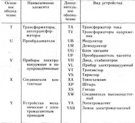
Standardized and most frequently used conditional graphic designations of ERA in the circuit diagrams are shown in Fig. 1. 1. These designations concern all component elements of schemes, including ERE, conductors and connections between them. And here the most important thing is that the condition of the correct designation of the same type of ERA and products is becoming. For this purpose, the positional notation is applied, the mandatory part of which is the letter designation of the type of element, the type of its design and the digital designation of the ERE number. The diagrams also use an additional part of the ERE position designation, indicating the function of the element, in the form of the letter. The main types of lettermarks of the schemes of schemes are given in Table. 1.1.
Designations in the drawings and schemes of general elements are referred to a qualification, setting current and voltage,. Type of compound, control methods, pulse form, modulation type, electrical communications, flow direction, signal, energy flow, etc.
Currently, the population and the trading network is in operation a significant amount of various electronic devices and devices, radio and television equipment, which are manufactured by foreign firms and various joint-stock companies. In stores you can purchase various types of Erie and Ereg with foreign symbols. In tab. 1. 2 shows information about the most common ERA of foreign countries with appropriate designations and their analogues of domestic production.
This information is first published in such a volume.
1-transistor structure P-N-P in the housing, general designation;
2- transistor structure N-P-N in the case, general designation,
3 - Field transistor with P-N transition and P canal,
4 - Field transistor with P-N transition and r channel,
5 - transistor single-pass with the base P type, B1, B2 - base conclusions, E - Emitter output,
6 - photodiode,
7 - rectifier diode,
8 - Stabilirt (avalanche rectifier diode) one-sided,
9 - heat-electric diode,
10 - dynotor diode, locked in the opposite direction;
11 - Stabilirt (diode-domain rectaging) with bilateral conductivity,
12 - thyristor triode;
13 - photoresistor;
14 - variable resistor, retaint, general designation,
15 - variable resistor,
16 - variable resistor with outlaps,
17 is a rapid resistor potentiometer;
18 - thermistor with a positive temperature coefficient of direct heating (heating),
19 - varistor;
20 - constant capacitor capacitor, general designation;
21 - a constant capacity capacitor polarized;
22 - condenser oxide polarized electrolytic, general designation;
23 - resistor permanent, general designation;
24 - resistor constant with a rated power of 0, 05 W;
25 - resistor permanent with a rated power of 0, 125 W,
26 - resistor permanent with a rated power of 0, 25 W,
27 - Resistor Permanent with a rated capacity of 0, 5 W,
28 - resistor permanent with a nominal capacity of 1 W,
29 - resistor permanent with a rated power of scattering 2 W,
30 - resistor constant with a rated power of scattering 5 W;
31 - resistor permanent with one symmetric additional discharge;
32 - resistor permanent with one asymmetrical additional discharge;

Figure 1.1 Conditional graphic designations ERE in electrical, radio and automation schemes
33 - Oxide capacitor unpolarized;
34 - passage condenser (arc refers to the case, external electrode);
35 - capacitor variable capacity (arrow indicates the rotor);
36 - Condenser trimmed, general designation;
37 - Varopond;
38 - condenser interference;
39 - LED;
40 - tunnel diode;
41 - incandescent lamp lighting and signal;
42 - electric call;
43 - galvanic or battery element;
44 - electrical communication line with one branch;
45 - a line of electrical connection with two branches;
46 - A group of wires connected to one point electrical connection. Two wires;
47 - four wires connected to one point by electrical connections;
48 - battery from galvanic elements or battery battery;
49 - coaxial cable. The screen is connected to the housing;
50 - transformer winding, autotransformer, choke, magnetic amplifier;
51 - Magnetic amplifier working winding;
52 - Magnetic amplifier control winding;
53 - a transformer without a core (magnetic pipeline) with a permanent connection (points marked startings);
54 - a transformer with a magnetodielectric core;
55 - inductor inductor, choke without magnetic pipeline;
56 - a single-phase transformer with a ferromagnetic magnetic core and a screen between windings;
57 - Transformer Single-phase three-winding with ferromagnetic magnetic core with a removal in the secondary winding;
58 - Single-phase autotransformer with voltage control;
59 - fuse;
60 - fuse switch;
61 - fuse-disconnector;
62 - Connection connector connection;
63 - amplifier (direction of signal transmission indicates the top of the triangle on the horizontal line);
64 - pin of the detachable contact connection;

Figure 1.1 Conditional graphic designations ERE in electrical radio engineering and automation schemes
65 - the slot of the detachable contact connection,
66 - Contact Collapsible Connection For example with clip
67 - Contact of an unbalanced compound, such as soldering
68 - switch push-button single-pole pressure with a closure contact of the self-radiation
69 - contact switching device opening, general designation
70 - contact switching device (switch, relay) closing, general designation. Single-pole switch.
71 - Coupling switching device switching, general designation. One-pole switch into two directions.
72- contact switching three-position with neutral position
73 - Contact closing without self-radiation
74 - Switch Push button push with open contact
75 - Switch Push-button exhaust with closing contact
76 - Switch push button push with button return,
77 - Switch push-button exhaust with open contact
78 - switch switch push with a return by means of secondary button presses,
79 - Electric relays with closing disconnecting and switching contacts,
80 - relay polarized on one direction of current in the winding with a neutral position
81 - relay polarized on both currents of current in the winding with a neutral position
82 - Electro-relentable relay without self-radiation, with a return by means of secondary pressing the button,
83 - detachable single-pole connection
84 - socket of the five-wire contact detachable connection
85 - pin contact detachable coaxial connection
86 - Contact Connection Nest
87 - pin four-wire connection
88 - four-wire jack
89 - Jumper Switching Splot Chain
Table 1.1. Letter designations of schemes

Continued Table 1.1.

Built on the basis of contact symbols: closing (Fig. 1, b), sparring (in, d) and switching (g, e). Contacts simultaneously closing or opening two chains are indicated, as shown in Fig. 1, (f, and i).
For the initial position of the closure contacts on electrical circuits, the open state of the switching electrical circuit, disconnecting - closed, switching - the position in which one of the chains is closed, the other is open (the exception is a contact with the neutral position). Hugo all contacts are allowed to portray only in a mirror or rotated at 90 ° positions.
A standardized hug system provides for reflection of such constructive features as the non-briefness of the operation of one or several contacts in the group, the absence or presence of fixing them in one of the provisions.
So, if it is necessary to show that the contact is closed or opened before others, the symbol of its movable part is complemented by a short stroke, directed towards the triggering (Fig. 2, a, b), and if later, - a stroke directed in the opposite direction (Fig. 2, B, d).
The lack of fixation in the closed or open positions (self-radiation) is denoted by a small triangle, the vertex of which is directed toward the initial position by the moving part of the contact (Fig. 2, D, E), and fixation - a circle on the symbol of its fixed part (Fig. 2, f, and).
The last two hugo on electrical circuits are used in cases where it is necessary to show a type of switching product, whose contacts are usually not possessed by these properties.
The conditional graphic designation of the switches on the electrical circuits (Fig. 3) is built on the basis of symbols of closures and disconnect contacts. It is understood that the contacts are fixed in both positions, i.e. do not have self-definition.

Fig. 3.
The letter code of this group is determined by the circuit and the constructive design of the switch. If the latter is placed in the control circuit, alarm system, measurements, it is denoted by the Latin letter S, and if in the power circuit - the letter Q. The control method is reflected in the second letter of the code: push-button switches and switches are indicated by the letter B (SB), automatic - letter F (SF), all the others - the letter A (SA).
If in the switch multiple contacts, the characters of their movable parts on electrical circuits are placed in parallel and connect the mechanical communication line. As an example in Fig. 3 shows the conditional graphic designation of the SA2 switch containing one opening and two closing contacts, and SA3, consisting of two closing contacts, and one of which (in the figure - right) closes later than the other.
Switches Q1 and Q2 serve to switch power circuits. Q2 contacts are mechanically associated with any control body, as evidenced by the segment of the stroke line. When contacting contacts in different sections of the circuit, the belonging to their one commuting product is traditionally reflected in (SA 4. 1, SA4.2, SA4.3).
Fig. four.
Similarly, based on the symbol of the switching contact, the conventional graphic designations of the two-position switches (Fig. 4, SA1, SA4) are built on electrical sections (Fig. 4, SA1, SA4). If the switch is fixed not only in the extreme, but also an average (neutral) position, the symbol of the movable part of the contact is prevented between the symbols of fixed parts, the possibility of rotation in both sides is shown by the point (SA2 in Fig. 4). The same is also received if you need to show a switch on the diagram, fixable only in the middle position (see Fig. 4, SA3).
The distinctive feature of the hugo switching switches and switches is the button symbol connected to the designation of the movable part of the mechanical communication line (Fig. 5). In this case, if the conditional graphic designation is built on the basis of the main contact symbol (see Fig. 1), this means that the switch (switch) is not fixed in the pressed position (when the button is released, it returns to its original position).

Fig. five.

Fig. 6.
If you need to show fixation, the symbols of fixation contacts are used specifically designed for this purpose (Fig. 6). Return to the starting position When you press another switch button, in this case the sign of the locking mechanism in this case, connecting it to the symbol of the moving part of the contact from the side opposite to the button symbol (see Fig. 6, Sb1.1, Sb 1.2). If the refund occurs when the button is repeatedly pressing, the locking mechanism is depicted instead of the mechanical communication line (SB2).
(for example, gallery) denoted as shown in Fig. 7. Here, SA1 (on 6 positions and 1 direction) and SA2 (on 4 positions and 2 directions) are switches with conclusions from moving contacts, SA3 (for 3 positions and 3 directions) - no conclusions from them. The conventional graphic designation of individual contact groups is depicted in the diagrams in the same position, the belonging to one switch is traditionally shown in the positional designation (see Fig. 7, SA1.1, SA1.2).
Fig. 7.

Fig. eight
For the image of multi-position switches with complex commutation, GOST provides several ways. Two of them are shown in Fig. 8. SA1 switch - on 5 positions (they are indicated by numbers; the letters of the A-D are introduced only for the explanation). In position 1, one on the other chain A and B, G and D, in positions 2, 3, 4, respectively, the chain b and r, A and B, A and D, in position 5 - chains A and B, V and G .
Switch SA2 - on 4 positions. In the first of them, chains A and B are closed (they are talking about the points located under them), in the second - chains in and g, in the third - in and g, in the fourth - b and G.
Zorin A. Yu.
The ability to read electrical strokes is an important component, without which it is impossible to become a specialist in the field of electrical work. Each starting electrician must know how to designate the electrical wiring sockets, switches, switching devices, and even the electricity meter in accordance with GOST. Next, we will provide the readers of the site conditional designations in electrical circuits, both graphic and alphabet.
Graphic
As for the graphic designation of all elements used in the diagram, we will provide this review in the form of tables in which products will be grouped by intended purpose.
In the first table you can see how electrical boxes, shields, cabinets and consoles are noted on electrical circuits:
The next thing you should know is the conditional designation of the supply sockets and switches (including passing) on \u200b\u200bthe unicineal schemes of apartments and private houses:

As for lighting elements, lamps and lamps according to GOST indicate as follows:


In more complex schemes where electric motors are used, such elements may be indicated as:

It is also useful to know how graphically designate transformers and chokes on fundamental electrical circuits:

Electrical instruments for GOST have the following graphic designation in the drawings:

But, by the way, useful for novice electricals table, in which it is shown as it looks like on the plane of the electrical wiring contour of the ground, as well as the power line itself:

In addition, in the diagrams, you can see a wavy or direct line, "+" and "-", which indicate the generation of the current, voltage and form of pulses:

In more complex automation schemes, you can meet incomprehensible graphic notation, such as contact compounds. Remember how it is indicated by the devices on the electrical circuits:


In addition, you should be aware of how radio elements look like on projects (diodes, resistors, transistors, etc.):

That's all conditionally graphic designations in the electrical circuits of power chains and lighting. As they already seen the components of quite a lot and remember, as it is designated only with experience. Therefore, we recommend that you keep all these tables so that when reading the project planning planning project or apartment, you could immediately determine what the element of the chain is in a certain place.
Interesting video
Any electrical chains can be presented in the form of drawings (fundamental and installation schemes), the design of which must comply with ECC standards. These rules are distributed both on the electrical wiring or power chains and electronic devices. Accordingly, to "read" such documents, it is necessary to understand the conditional designations in electrical circuits.
Regulations
Given the large number of electrical elements, for their alphanumeric (hereinafter Bo) and conditionally graphic designations (HGO) a number of regulatory documents were developed excluding differences. Below is a table in which the main standards are presented.
Table 1. Standards of graphic designation of individual elements in assembly and fundamental electrical circuits.
| Gosta number | Short description |
| 2.710 81 | This document contains the requirements of the GOST to bo of various types of electrical elements, including electrical appliances. |
| 2.747 68 | Requirements for the size of the display of elements in graphical form. |
| 21.614 88 | Accepted norms for electrical equipment and wiring plans. |
| 2.755 87 | Display on switching devices and contact compounds |
| 2.756 76 | Norms for perceiving parts of electromechanical equipment. |
| 2.709 89 | This standard regulates the norms, in accordance with which contact connections and wires are indicated in the schemes. |
| 21.404 85 | Schematic designations for equipment used in automation systems |
It should be borne in mind that the element base changes over time, the changes and the regulatory documents are made accordingly, the truth is more inert. We give a simple example, the UDO and the diffantomates are widely operated in Russia for more than a decade, but the Unified Standard on GOST 2.755-87 standards has not yet been not, unlike circuit breakers. It is possible that in the near future this question will be settled. To keep up to date with such innovations, professionals are tracking changes in regulatory documents, fans do not do this, it is enough to know the decoding of the main designations.
Types of electrical schemes
In accordance with the ECC standards, the schemes include graphic documents, on which, using adopted designations, the main elements or structural nodes are displayed, as well as combining their bonds. According to the adopted classification, ten species of schemes are distinguished from which in electrical engineering, most often, three are used:
If only the power portion of the installation is displayed on the diagram, then it is called a one-core, if all the elements are given, then - complete.


If an apartment wiring is displayed in the drawing, the location of the lighting devices, sockets and other equipment is indicated on the plan. Sometimes you can hear how such a document is called the power supply scheme, it is incorrect, since the latter displays the method of connecting consumers to a substation or other power source.
Having understood with electrical circuits, we can move to the designations of the elements specified on them.
Graphic designations
For each type of graphical document, there are references regulated by the relevant regulatory documents. We give as an example basic graphic notation for different types of electrical circuits.
Examples of hug in functional schemes
Below is a picture with the image of the main nodes of automation systems.
 Examples of conventional designations of electrical appliances and automation means in accordance with GOST 21.404-85
 Description of the designation:
- A - main (1) and allowable (2) images of devices that are installed outside the electrical wheel or junction box.
- B is the same as item A, except that the elements are located on the remote or electrical protection.
- C is the display of executive mechanisms (im).
- D - the influence of the regulatory authority (hereinafter RO) when the power is turned off:
- The opening of RO occurs
- Closing RO
- The position of RO remains unchanged.
- E - to them, which is additionally installed manual drive. This symbol can be used for any PO provisions specified in paragraph D.
- F-received display lines:
- General.
- There is no connection when crossing.
- The presence of a connection when crossing.
Hugo in monolay and complete electrical strokes
For these schemes, there are several groups of symbols, we give the most common of them. To obtain full information, you need to contact the regulatory documents, the number of state standards will be shown for each group.
Power sources.
For their designation, the characters shown in the figure below are taken.
 Hugo power sources on conceptual circuits (GOST 2.742-68 and GOST 2.750.68)
 Description of the designation:
- A is a constant voltage source, its polarity is indicated by the characters "+" and "-".
- B - electricity icon displaying alternating voltage.
- C is a symbol of variable and constant voltage, used in cases where the device can be erected from any of these sources.
- D - mapping a battery or galvanic power supply.
- E is a battery symbol consisting of several batteries.
Links
The basic elements of the electrical connectors are presented below.
 Designation of communication lines on conceptual circuits (GOST 2.721-74 and GOST 2.751.73)
 Description of the designation:
- A is a general map adopted for various types of electrical connections.
- B - Cottage or grounding tire.
- C - the screening designation may be electrostatic (marked with the symbol "E") or electromagnetic ("M").
- D - ground symbol.
- E - electrical connection with the body of the device.
- F - on complex circuits, of several components, thus designated communication, in such cases "x" is information about where the line will continue (as a rule, the element number is indicated).
- G - intersection with no connection.
- H - connection at the intersection site.
- I - branches.
Designations of electromechanical devices and contact compounds
Examples of the designation of magnetic starters, relays, as well as contacts of communication devices, can be viewed below.
 Hugo adopted for electromechanical devices and contactors (Gosta 2.756-76, 2.755-74, 2.755-87)
 Description of the designation:
- A - symbol of the coil of an electromechanical instrument (relay, magnetic starter, etc.).
- B - Hugo perceived part of the electrothermal protection.
- C is the display of the coil of the device with a mechanical lock.
- D - Contacts of switching devices:
- Circuit.
- Blinding.
- Switchable.
- E - symbol for designation of manual switches (buttons).
- F - group switch (switch).
Hugo Electromashin
We give a few examples, display of electrical machines (hereinafter EM) in accordance with the current standard.
 Designation of electric motors and generators on conceptual circuits (GOST 2.722-68)
 Description of the designation:
- A - three-phase uh:
- Asynchronous (rotor is short-circuit).
- Also, and point 1, only in two-speed execution.
- Asynchronous EM with the phase execution of the rotor.
- Synchronous motors and generators.
- B - Collector, with DC powered:
- EM with excitation on a constant magnet.
- EM with an excitation coil.

Hugo transformers and chokes
Examples of graphic designations of these devices can be found in the figure below.
Description of the designation:
- A - this graphic symbol can be indicated by inductor inductors or winding of transformers.
- In - choke, which has a ferrimagnetic core (magnetic circuit).
- C is the display of the two-screw transformer.
- D - device with three coils.
- E - the symbol of the autotransformer.
- F is a graphical display of TT (current transformer).
Designation of measuring instruments and radio components
A brief overview of the coo data of electronic components is shown below. Those who want to more widely familiarize themselves with this information recommend to view Gosta 2.729 68 and 2.730 73.
 Examples of conventional graphic designations of electronic components and measuring instruments
 Description of the designation:
- Electricity meter.
- An ammeter image.
- The device for measuring the voltage of the network.
- Thermal sensor.
- Resistor with a constant face value.
- Variable resistor.
- Condenser (general designation).
- Electrolytic container.
- Diode designation.
- Light-emitting diode.
- An image of a diode optopara.
- Hugo transistor (in this case NPN).
- Fuse designation.
Hugo lighting devices
Consider how electrical lamps are displayed on the concept.

Description of the designation:
- A - general image of incandescent bulbs (LN).
- B - LN as alarm.
- C is a typical designation of gas-discharge lamps.
- D - gas-discharge source of high pressure light (the figure shows an example of execution with two electrodes)
Designation of elements in the wiring circuit
Completing the topic of graphic designations, we give examples of displaying sockets and switches.

As other types of outlets are depicted, easy to find in regulatory documents that are available on the network.


 How to return the love of her husband to his wife - Tips of the psychologist
 Why you can not give icons