Do-it-yourself motion sensor on arduino. Low-cost GSM alarm system with brains from Arduino. How it works
This project concerns the development and improvement of a system to prevent / control any attempts to enter by thieves. Developed by security device Uses an embedded system (includes a hardware microcontroller using open source software and a gsm modem) based on GSM (Global System for Mobile Communications) technology.
A security device can be installed in the house. The interface sensor for the burglar alarm is also connected to the controller-based burglar alarm system.
When an attempt is made to penetrate, the system sends a warning message (for example, sms) to the owner on mobile phone or to any pre-configured mobile phone for further processing.

The security system consists of microcontroller arduino Uno and a standard SIM900A modem based on GSM / GPRS. The whole system can be powered by any 12V 2A power supply / battery.
Below is a diagram of an Arduino-based security system.
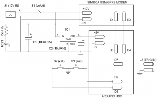
The operation of the system is very simple and self-explanatory. When power is applied to the system, it enters standby mode. When the pins of connector J2 are shorted, a preprogrammed warning message is sent to the required mobile number. You can connect any intrusion detector (such as a light guard or motion detector) to the J2 input connector. Note that the active-low (L) signal on pin 1 of J2 will activate the burglar alarm.
Moreover, an optional “call - alarm” device has been added to the system. It activates phone call when the user presses the S2 button (or when another electronic unit triggers an alarm). After pressing the “call” button (S2), the call can be canceled by pressing another button S3 - the “end” button. This option can be used to generate a “missed call” alarm in the event of intrusion.
The circuit is very flexible, so it can use any SIM900A modem (and of course the Arduino Uno board). Read the documentation for your modem carefully before starting assembly. This will make the process of making the system easier and more enjoyable.
List of radioelements
| Designation | Type of | Denomination | Quantity | Note | Shop | My notebook |
|---|---|---|---|---|---|---|
| Arduino board | Arduino Uno | 1 | Into notepad | |||
| GSM / GPRS modem | SIM900A | 1 | Into notepad | |||
| IC1 | Linear regulator | LM7805 | 1 | Into notepad | ||
| C1 | 100μF 25V | 1 | Into notepad | |||
| C2 | Electrolytic capacitor | 10mkF 16V | 1 | Into notepad | ||
| R1 | Resistor | 1 kΩ | 1 | Into notepad | ||
| LED1 | Light-emitting diode | 1 | Into notepad | |||
| S1 | Button | With fixation | 1 |
Today we will talk about how using Arduino to collect security system ... Our "guard" will guard one circuit and control one siren.
For Arduino, this is not a problem, and, as you will see from the program code and the device diagram, you can easily increase the number of protected access points and the number of warning or indication devices.
Security system can be used to guard both large objects (buildings and structures) and small items(boxes, safes), and even portable cases and suitcases. Although you need to be more careful with the latter, if you install a security system, for example, on a suitcase with which you decide to go on a trip, and the warning system goes off at some airport, then I think you will have a serious conversation with the local security service :-)
In a simplified way, the principle of operation of the device is as follows (Fig. 1). After turning on the power, the device enters the operating mode and waits for arming. Arming and disarming are carried out with one button. To increase security, it is better to place this button inside the protected area (safe or box). Before turning on the security mode, the door must be slightly opened. When the security mode is turned on (by pressing the button) electronic circuit waits until you close the door to the room (safe door, box lid, etc.).

A limit switch of any type must be installed on the door (or door), more on that later. By closing (or opening), the limit switch will inform the device that the protected circuit is closed, and the device will switch to the armed mode. The system will notify about the transition to the security mode with two short signals (as in car alarms). In this mode, the device "catches" the opening of the door. After opening the door, the system waits for a few seconds (this is a configurable value, for rooms about ten seconds, for a box one or two) for disarming, if this does not happen, the siren turns on. The algorithm and circuit are designed in such a way that you can turn off the siren only by completely disassembling the case and turning off the power.

Device security system very simple (fig. 2). At the heart of the fee Arduino... The limit switches are connected like a regular button through pull-up resistors. I will dwell on the limit switches separately. They are normally closed and normally open. You can turn on a regular button as a limit switch, only a stroke regular button very large, door play is usually greater. Therefore, it is necessary to come up with some kind of pusher for the button and spring it so as not to break the button with the door. Well, if not laziness, then you can walk to the store and buy a magnetic switch (reed switch) (Fig. 3), it is not afraid of dust and dirt.

A limit switch for car alarms is also suitable (Fig. 4). It should be noted that the program is written for a reed switch. At closed door its contact is closed. If you use a switch from a car alarm, then when the door is closed, it will most likely be open, and in the appropriate places in the code you will need to change 0 to 1 and vice versa.

As a siren, I propose to use a sound annunciator PKI-1 IVOLGA made in Belarus (Fig. 5). Supply voltage 9 - 15 V, operating current 20 - 30 mA. This allows it to be used with battery power. At the same time, it "gives out" 95 - 105 dB.

With such characteristics from the "Krona" battery, it will sound for several tens of minutes. I found it on the Internet for 110 rubles. There, a reed switch with a magnet costs about 30 rubles. The car alarm switch in auto parts was purchased for 28 rubles. The KT315 transistor can be taken with any letter or replaced with any modern low-power silicon transistor of appropriate conductivity. If the volume of one siren is not enough (who knows, maybe you want it to be heard for many kilometers), you can connect several sirens in parallel or take a more powerful one, only in this case the transistor must be replaced with a more powerful one (for example, the familiar transistor assembly ULN2003). As connectors for connecting a reed switch and a siren, I used the simplest connectors for audio / video devices - the price on the radio market is 5 rubles. for a couple.
The body of the device can be glued from plastic or plywood; if a serious object is guarded, then it is better to make it metal. Batteries or rechargeable batteries should be placed inside the case to increase reliability and safety.
To simplify the program code, no energy saving elements were used, and the batteries are not enough for a long time. You can optimize the code, or even better, radically alter it by applying interrupt event handling and MK hibernation. In this case, the power supply from two square batteries connected in series (9 V) should last for several months.
Now the code
// constants
const int button = 12; // pin for the button
const int gerkon = 3; // pin for reed switch
const int sirena = 2; // pin control of the siren
const int led = 13; // indicator pin
// variables
int buttonState = 0; // button state
int gerkonState = 0; // state of the reed switch
int N = 0; // counter of the disarming button
void setup () (
// siren and indicator control - exit
pinMode (sirena, OUTPUT);
pinMode (led, OUTPUT); // push button and reed switch are inputs
pinMode (gerkon, INPUT);
pinMode (button, INPUT);
}
void loop () (
digitalWrite (led, HIGH);
while (buttonState = = 0) (// wait loop until we press the button
buttonState = digitalRead (button); // to switch to security mode
}
digitalWrite (led, LOW);
buttonState = 0; // zero the value of the button
while (gerkonState = = 0) (// loop until we close the door
}
delay (500); // :-)
digitalWrite (sirena, HIGH); // Code
delay (100); // indications
digitalWrite (sirena, LOW); // include
delay (70); // mode
digitalWrite (sirena, HIGH); // guard
delay (100); // alert
digitalWrite (sirena, LOW); // sound
while (gerkonState = = 1) (// wait for the door to open
gerkonState = digitalRead (gerkon);
}
for (int i = 0; i<= 5; i++){ // 7,5 секунды на нажатие
buttonState = digitalRead (button); // secret button
if (buttonState = = HIGH) (// keep track of our own - stranger
N = N + 1;
}
delay (1500); // secret feature :-)))
}
if (N> 0) (// most important
digitalWrite (sirena, LOW); // don't turn on the siren
}
else (
digitalWrite (sirena, HIGH); // or turn on the siren
}
digitalWrite (led, HIGH); // turn on the indicator N = 0;
buttonState = 0;
delay (15000); // reminder for dummies who like
digitalWrite (led, LOW); // press the buttons without interruption delay (1000);
GSM alarm on Arduino
In this article, you will learn how to (buy) make your own GSM signaling using a GSM module and Arduino very cheaply. The object of protection of the GSM alarm system is ideal dacha is suitable, house, garage, apartment.
Step 1: elements
For this project you will need:
GSM Shield
Buzzer
Alarm siren 12V
12V power supply
Arduino keyboard
Frame.
Step 2: Connecting the Components 
First, you put the GSM module on the Arduino Uno, you will need to solder the GND and VCC wires along with two sensors, a buzzer and the input of the relay module. Then connect these soldered wires to the corresponding connector on the GSM shield. Next, you will make a signal I / O connector from these parts, and the last thing you need to do is connect a keyboard
Arduino Uno / GSM Terminals:
Conclusion 0: not linked;
Conclusion 1: not linked;
Pin 2: unbound (GSM will use this pin);
Pin 3: unbound (GSM will use this pin);
Pin 4: the last line using the keyboard (keyboard pin 4 - from 8);
Conclusion 5: not linked;
Pin 6: second column using the keyboard (keyboard pin 6 - from 8);
Conclusion 7: the third column from the keyboard (keyboards of finger 7 - from 8);
Pin 8: unbound (GSM will use this pin);
Pin 9: unbound (GSM will use this pin);
Conclusion 10: data of PIR sensor No. 2;
Conclusion 11: siren sound signal (goes to the input of the relay module);
Conclusion 12: data of PIR sensor # 1;
Pin 13: Buzzer signal input;
As you can see, although the keyboard has 8 pins, only three are connected (one row and two columns, which allows two numbers to be read - 1 × 2 matrices), so I can make passwords using these three wires, and there is no need to use all contacts from the keyboard. This is because after the motion sensor detects a person walking in the room, the person will only have 5 seconds to turn off the alarm. After Emergency Signal does not turn off on this moment time, GSM shield sends SMS to you, or calls your phone number. The Arduino has been programmed to make a call and as soon as you answer the phone, it hangs up.
Of course, you can get false sensor readings, so there is an option to disable the alarm by simply sending SMS from your phone to the Arduino. Also, another option you can do is set up your shield to send you one message a day so you know it is working correctly.
Step 3: Code
Just download the below code and compile. It uses the Keypad.h and GSM.h libraries.
Download file: (Downloads: 181)
Download file: (Downloads: 104)
Step 4: Conclusion
Given that the Arduino Uno code will send SMS messages and ring your phone in just five seconds after someone breaks into your house, I guess you will have enough time to call the police. Of course, the siren will scare off thieves and your house or other premises will become safer with the help of this article.
Let's get started!
What will we collect
We must choose the heart of our system. In my opinion, there is nothing better for such signaling than the Arduino Uno. The main criterion is enough"Pins" and price.
The main Arduino specifications Uno
Microcontroller - ATmega328
Working voltage - 5 V
Input voltage (recommended) - 7-12 V
Input voltage (limit) - 6-20 V
Digital Inputs / Outputs - 14 (of which 6 can be used as PWM outputs)
Analog Inputs - 6
DC current through input / output - 40 mA
DC current for 3.3 V pin - 50 mA
Flash Memory - 32KB (ATmega328) of which 0.5KB is used for bootloader
RAM - 2 KB (ATmega328)
EEPROM - 1 KB (ATmega328)
Clock frequency - 16 MHz
Fits!
Now you need to select a gsm module, because our alarm system should be able to notify the owner of the car. So, you need to google ... Here, an excellent sensor - SIM800L, the size is just wonderful.

I thought and ordered it from China. However, everything turned out to be not so rosy. The sensor simply refused to register the SIM card on the network. Everything that was possible was tried - the result was zero.
Found kind people which provided me with the cooler Sim900 Shield. This is already a serious thing. The Shield has a microphone and headphone jack, a full-fledged phone.

Main features of Sim900 Shield
4 standards of working frequency 850/900/1800/1900 MHz
GPRS multi-slot class 10/8
GPRS mobile station class B
Compliant with GSM phase 2/2 +
Class 4 (2 W @ 850/900 MHz)
Class 1 (1 W @ 1800 / 1900MHz)
Controlled by AT commands (GSM 07.07, 07.05 and SIMCOM extended AT commands)
Low power consumption: 1.5mA (sleep mode)
Operating temperature range: -40 ° C to +85 ° C
Fits!
Ok, but you have to take readings from some sensors to notify the owner. Suddenly the car is evacuated, then the position of the car will obviously change in space. Let's take an accelerometer and a gyroscope. Fine. Dachshund, now we are looking for a sensor.
I think the GY-521 MPU6050 will definitely fit. It turned out that it also has a temperature sensor. It would be necessary to use it, there will be such a "killer feature". Suppose the owner of the car put it under the house and left. The temperature inside the car will change "smoothly". What happens if an intruder tries to break into a car? For example, he will be able to open the door. The temperature in the car will begin to change rapidly, as the air in the cabin begins to mix with air. environment... I think it will work.

Main features of GY-521 MPU6050
3-axis gyroscope module + 3-axis accelerometer GY-521 on the MPU-6050 chip. Allows you to determine the position and movement of an object in space, angular velocity when rotating. It also has a built-in temperature sensor. It is used in various copters and aircraft models, it is also possible to assemble a motion capture system based on these sensors.
Microcircuit - MPU-6050
Supply voltage - from 3.5V to 6V (DC);
Gyroscope range - ± 250 500 1000 2000 ° / s
Accelerometer Range - ± 2 ± 4 ± 8 ± 16g
Communication interface - I2C
Size - 15x20 mm.
Weight - 5 g
Fits!
A vibration sensor is also useful. Suddenly, they will try to open the car with "brute force", or, in the parking lot, another car will touch your car. Take the vibration sensor SW-420 (adjustable).

Main features SW-420
Supply voltage - 3.3 - 5V
Output signal - digital High / Low (normally closed)
Used sensor - SW-420
Comparator used - LM393
Dimensions - 32x14mm
Additionally - There is an adjusting resistor.
Fits!
Screw on the SD memory card module. We will also write a log file.

Main characteristics of the SD memory card module
The module allows you to store, read and write to the SD card the data required for the operation of the device based on the microcontroller. The use of the device is relevant when storing files from tens of megabytes to two gigabytes. The board contains an SD card container, a card power stabilizer, a plug for the interface and power lines. If you need to work with sound, video or other volumetric data, for example, to keep a log of events, sensor data or store information from a web server, then the SD memory card module for Arduino will make it possible to use an SD card for these purposes. Using the module, you can study the features of the SD card.
Supply voltage - 5 or 3.3 V
SD card memory capacity - up to 2 GB
Dimensions - 46 x 30mm
Fits!
And let's add a servo, when the sensors are triggered, the servo with a video recorder will turn and shoot video of the incident. Take the MG996R servo.

Main features of MG996R servo
Stable and reliable protection from damage
- Metal drive
- Double row ball bearing
- Wire length 300 mm
- Dimensions 40x19x43mm
- Mass 55 gr
- Angle of rotation: 120 degrees.
- Working speed: 0.17sec / 60 degrees (4.8V no load)
- Working speed: 0.13sec / 60 degrees (6V no load)
- Starting torque: 9.4kg / cm at 4.8V power supply
- Starting torque: 11kg / cm at 6V power supply
- Working voltage: 4.8 - 7.2V
- All drive parts are made of metal
Fits!
We collect
There are a lot of articles about connecting each sensor in Google. And I have no desire to come up with new bicycles, so I will leave links to simple and working options.Good time of day 🙂 Today we'll talk about alarm. The service market is full of companies, organizations that are engaged in the installation and maintenance of security systems. These firms offer the buyer a wide variety of alarm systems. However, their cost is far from cheap. But what should a person who does not have so many personal funds to do that can be spent on burglar alarm? I think the conclusion suggests itself - do alarm by their by hand... This article provides an example of how you can make your own coded security system using an Arduino uno board and several magnetic sensors.
The system can be deactivated by entering the password from the keypad and pressing the ‘ * ‘. If you want to change the current password, you can do it by pressing the ‘ B', And if you want to skip or interrupt the operation, you can do it by pressing the key ‘#’. The system has a buzzer for playing various sounds when performing a particular operation.
The system is activated by pressing the 'A' button. The system gives 10 seconds to leave the premises. After 10 seconds the alarm will be activated. The number of magnetic sensors will depend on your own desire... The project involves 3 sensors (for two windows and a door). When the window is opened, the system is activated and the alarm goes off from the buzzer. The system can be deactivated by entering a password. When the door is opened, the alarm gives the visitor 20 seconds to enter the password. The system uses an ultrasonic sensor that can detect movement.
Video of device operation
Craft made for informational / educational purposes. If you want to use it at home, you will need to refine it. Enclose the control unit in a metal case and secure the power line from possible damage.
Let's get started!
Step 1: what we need

- Arduino uno board;
- high-contrast LCD display 16 × 2;
- 4 × 4 keyboard;
- 10 ~ 20kΩ potentiometer;
- 3 magnetic sensors (they are also reed switches);
- 3 2-pin screw terminals;
- HC-SR04 ultrasonic sensor;
If you want to build a system without using Arduino, you will also need the following:
- DIP connector for atmega328 + atmega328 microcontroller;
- 16MHz crystal resonator;
- 2 pcs. 22pF ceramic, 2 pcs. 0.22uF electrolytic capacitor;
- 1 PC. 10k ohm resistor;
- power socket (DC power jack);
- bread board;
- 5V power supply;
And one box to pack it all!
Instruments:
- Something that can cut a plastic box;
- Hot glue gun;
- Drill / screwdriver.
Step 2: Alarm circuit

The connection diagram is quite simple.
Small clarification:
High contrast LCD:
- Pin1 - Vdd to GND;
- Pin2 - Vss to 5V;
- Pin3 - Vo (to the center pin of the potentiometer);
- Pin4 - RS to pin 8 of Arduino;
- Pin5 - RW to GND;
- Pin6 - EN to pin 7 of Arduino;
- Pin11 - D4 to pin 6 of Arduino;
- Pin12 - D5 to pin 5 of Arduino;
- Pin13 - D6 to pin 4 of Arduino;
- Pin14 - D7 to pin 3 of Arduino;
- Pin15 - Vee (to the right or left pin of the potentiometer).
4 × 4 keyboard:
Left to Right:
- Pin1 to A5 pin of Arduino;
- Pin2 to A4 pin of Arduino;
- Pin3 to A3 pin of Arduino;
- Pin4 to A2 pin of Arduino;
- Pin5 to pin 13 of Arduino;
- Pin6 to pin 12 of Arduino;
- Pin7 to pin 11 of Arduino;
- Pin8 to pin 10 of Arduino.
Step 3: Firmware

The step presents the code that is used by the built-in!
Download the codebender plugin. Click on the "Run" button in the Arduino and flash your board with this program. That's all. You've just programmed the Arduino! If you want to make changes to the code, click the "Edit" button.
Note: If you will not be using Codebender IDE to program your Arduino board, you will need to install additional libraries in the Arduino IDE.
Step 4: making your own control board

After successfully assembled and tested new project based on Arduino uno, you can start making your own board.
A few tips for a more successful completion of the undertaken:

- A 10K resistor must be wired between the 1 (reset) and 7 (Vcc) pins of the Atmega328 microcontroller.
- A 16MHz crystal should be connected to pins 9 and 10, labeled XTAL1 and XTAL2
- Connect each lead of the resonator with 22pF capacitors. Lead free capacitor leads to pin 8 (GND) of the microcontroller.
- Remember to connect the second ATmega328 power line to the power supply, the 20-Vcc and 22-GND pins.
- You can find more information on the microcontroller pins in the second image.
- If you plan to use a power supply with a voltage higher than 6V, you must use a linear regulator LM7805 and two 0.22uF electrolytic capacitors, which should be mounted at the input and output of the regulator. It is important! Do not apply more than 6V to the board !!! Otherwise you will burn your Atmega microcontroller and LCD display.
Step 5: Place the circuit in the case

 Spelling the suffixes of different parts of speech
 Higher professional education
 Rebus in Russian