How to make a stand for a soldering iron. The third hand and a stand for a soldering iron with your own hands Homemade functional stands for a soldering iron
Main tool home radio amateur - soldering iron. Unlike other appliances, it cannot simply be placed on a table (workbench) during operation. Why? Correctly! He is hot. Therefore, you will need a special stand.
- 1 Required minimum for stand
- 2 Flipping through old magazines
- 3 Third hand - work comfortably
- 3.1 Best Options
- 4 Stand and power regulator for soldering iron
- 4.1 You will need the following items
There are many different devices on sale, from a simple holder to a whole complex called a soldering station.
In most cases, a soldering iron is needed to perform urgent repair work. If you are not a professional "homemade" - the instrument usually gathers dust in a box on the balcony, appearing once or twice a year. In such cases, many use the first object that comes across as a stand.
However, if you put in quite a bit of effort, a hand-made soldering iron stand will look no worse than a factory one. Especially if you regularly make electrical circuits.

Required minimum for stand
Flipping through old magazines
In old Radio magazines, you can find drawings on how to make a stand with an economical load switch.

- As a basis (1) a board with a selected middle is used, or U-shaped design from a strip of plywood and two bars along the long edges
- Under the surface there is a relay contact group for 220 volts (2,4,5) with large current collection areas. The wiring diagram transfers power either directly or through a diode. The radio element "cuts off" the half-cycle of the alternating voltage of 220 volts, reducing it to a value of 110
- Through the rod (6), the spring-loaded (7) button (8) presses the contacts when the soldering iron lies on the stand. Electricity is spent half as much, while the soldering iron almost instantly warms up to full power. The rod is attached to the console (9)
- The tool itself is located on the brackets (3) and (10)
- At the rear is a soldering iron socket connected to the relay output contacts. Connected to the input power wire food
- Between the racks, they usually nailed a tin of shoe cream or petroleum jelly to store rosin
The design is simple, but convenient and effective. If you don’t want troubles with contacts, we make a simple functional stand. Again, from the experience of Soviet radio amateurs.


Third hand - work comfortably
When soldering by weight, it becomes necessary to hold two parts and a soldering iron at the same time. This is where the term "third hand" comes from. In the next review, a homemade stand with such a device.
The materials and tools that will be needed for manufacturing are shown in the photo:

Factory made parts - crocodile clips, decorative candles(more precisely, cups from them), a flexible leg from an old mini lamp and a spring holder. The donor was a Chinese stand for a soldering iron with a magnifying glass.

Although you can make such a spiral with your own hands by winding a steel wire around a pipe or a screwdriver handle. The rest of the blanks are also replaceable, homemade is shareware, from improvised trash.
With a drywall crown, we mill recesses for cups from candles. Two niches for rosin and solder, and one niche for cleaning cloth.

AT comfortable spot(not in the center) we mount the spiral holder for the soldering iron. Practice has shown that such a scheme is more convenient than the classic horn stand for a soldering iron. The appliance is inserted in one motion, without fear that it will fall on the table.

We install aluminum cups in prepared niches, cut off the edges flush with the board. The use of thin-walled containers justifies itself when working with low-power soldering irons. The less metal, the lower the heat capacity. The thick walls of the solder cup can cool the small tip of the soldering iron when touched. A thin aluminum foil surrounded by wood, on the contrary, retains heat.

We crimp the "crocodiles" on a flexible rod, and fix the "third hand" on the stand. There are designs with a magnifying glass. Experience shows that the stand for the soldering iron, on which the clamps and magnifier are installed, is inconvenient to use.
Best Options
- the magnifying glass is combined with the "third hand", the soldering iron is separate
- "third hand" on a stand with a soldering iron, a magnifying glass on a separate pedestal (our version).

The only thing missing is the ability to change temperature conditions work. This is especially true when mounting LEDs.
Stand and power regulator for soldering iron
The simplest and relatively affordable option, this is the purchase of a Chinese kit soldering station. You will assemble such a KIT yourself, so we will classify it as homemade.

It can be assembled in a stand case or as a separate unit. The convenience of this design is undeniable, but we consider the least expensive options. There is a 220 volt soldering iron in almost every home, it remains to assemble a power regulator.
Important! Dimers for incandescent lamps can be used, taking into account the power of the soldering iron.
But again, you have to buy them. Consider a simple scheme for a home-made regulator with a power of up to 200 watts.
You can use an autotransformer, but this is a bulky device with low efficiency. Let's leave such "devices" for the museum of radio engineering. Our triac circuit is miniature and economical.

You will need the following items
The circuit provides continuous operation with a load of 200-300 watts. Short-term load up to 500 W is allowed.
Drawing circuit board for self pickling:

We carefully assemble the board, carefully soldering the legs of the parts. If the contact is broken, uncontrolled voltage surges can be obtained at the output.

The circuit is compact, it can easily fit on a soldering iron stand. At power up to 100 W, triac cooling is not required. Bree greater load - a small radiator is attached to the case.

After reviewing the material, you yourself will decide which stand to make. Or look visual video a lesson on making a stand with your own hands.
Many of us work with radio components, some are professional, some are at the level of a radio amateur, but this is not important, since soldering something is an interesting and exciting process, and everyone has a soldering iron for this, and, of course, no matter what stand, then whether it simple lid rolled from a can, or already bought in a store finished construction, nevertheless, all these devices simplify our work, the more convenient it is done, the easier it is to work. For these purposes, it was decided to make something universal, a good assistant with good functionality, and at the same time use the material and mechanisms common in everyday life, which will not be difficult to find if desired. And now I will tell you how to do it.
Initially, I wanted to make something simple, namely a soldering iron holder with a temperature controller, since the soldering iron overheated, but once I started, I could not stop. All necessary fixtures did gradually, and therefore each time there were new and new ideas.
So, we need:
Material:
Chipboard board;
Bolts of different diameters;
Screws, self-tapping screws;
Nut-Lamb (10 pcs.);
Crocodiles (3 pcs.);
Door hinge (1 pc.);
Unnecessary flashlight;
3 motors (2 from the printer, 1 weaker from the typewriter);
4 LEDs (3.5 volts);
5 switches;
Collet;
Small sharpening nozzle (from the set for the engraver);
Helium paste (adapter for nozzle);
wires;
soldering iron;
3 corrugated tubes (from a gas lighter);
Cigarette case;
Tin coil;
Socket;
Doorhandle;
4 meters of cable;
2 power supplies (from a 5-volt phone charger and a 9-volt router);
Self-adhesive film, edge;
Black paint;
Tool:
soldering iron;
Glue gun;
Chisel;
Metal scissors.
So, let's begin
We take a chipboard board, mark it out and cut it out in an L-shape, the dimensions are attached.

At a specially selected place, we mark and cut out holes for push-button switches (4 pcs.).

In order to conveniently place our devices, and they could be adjusted, double L-shaped levers were made, cut out of tin, for each individually.
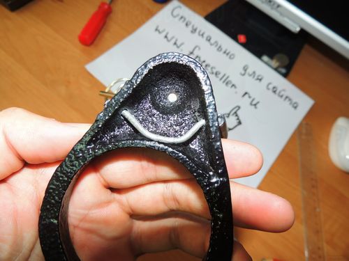
The cheapest soldering iron stand was bought.

And now we will refine it!
It was decided to make 2 crocodile holders, for this we drill 2 holes on the sides, take a steel wire, and push it through the bottom.
Next, we bring the ends to the top, level them flush with each other, bend them so that they look solid? we take 2 corrugated tubes taken from a gas lighter, put it on a wire, and then we attach a crocodile on each side, and also drill a hole in the saucer in order to screw it tightly to the surface of the board, as a result we get.

We make the third vertical crocodile, bend it in this way.

It is attached to the bottom of the stand.

It was decided to make a mini drill, as well as a sharpener for small parts. For this, 2 unnecessary motors were taken from the printer.

A sharpening nozzle was attached to the motor, using an adapter from a helium pen. The motor itself was fixed to the found metal form, in such a way that it could stand upright.
In order to be able to work at night, we make lighting from an unnecessary flashlight, in my case of this type.

We remove the excess, and leave only the part with the LED.

In order for the lantern to move up and down, an adapter (cap) was taken, a through hole was drilled, a long bolt was inserted, holders were cut out, and everything was clamped with a wing nut, in this way.


Sometimes you have to work in hot weather, so I wanted to add such a nice little thing as a fan. We take the most common motor and make a case for it. The broken charger from nokia was optimally sized. We cut off the plug, take out the core and cut out a place for the motor.

The wires were soldered, assembled it looks like this.

In order to be able to solder small elements, we take a magnifying glass, remove the excess and make a backlight using 4 LEDs of 5 volts each, and fasten it with a glue gun.
 |
 |

We fix everything in place and get it.

We put the switch.

 |
 |

We cut out two plates, bend them in the form of a slingshot, drill, and thread a long bolt, this is how it all looks.

We fix to the body of our mini drill, in this way.

In order for the stand to be used anywhere, add 4 meters of cable and the usual door handle, for its winding.

Drill 2 holes for the fork.
 |
|


We drill 4 holes for fastening, we make partitions.

We put together everything you need.

We make the main holder for the soldering iron, handle and tip.
Cut out 2 plates, bend, fasten to door hinge, and from below to the board itself.
The door hinge is needed so that when unwinding the cable, we can remove the soldering iron to the side, and it does not interfere with us.
|
|
|


Since the soldering iron overheated a lot, and it was almost impossible to solder, it was decided to make a temperature controller, after looking at the diagrams, etc., I decided that it would be easier to buy an inexpensive dimmer (dimmer) of this type.

Having disassembled it, and cut out a place for the board in the board, brought 2 wires to the bottom, left one half of the case, and drilled a hole in the middle for the regulator wheel.
 |
|

Attached to board with 2 screws.

I'll post the wiring diagram below.
In order to be able to work in one place, as well as for convenience, we put an outlet, which makes it possible to connect glue gun, phone charging, etc. things.

We make such a delivery, where you can put a jar of flux, or something else. Cut out of an old watch case.

When all the fixtures are ready and painted black, glue the self-adhesive film onto the surface of the board. Was chosen light color, since all the details are clearly visible on such a surface, the side faces are glued with an edge.
A do-it-yourself soldering iron stand is necessary when working with a tool. Factory devices are mostly not practical and do not have additional features that make the job much easier.

Using something as a coaster usually results in a burnt table surface, clothes spoiled by tin and rosin, and hand burns.
Working on the “knee” is not quite convenient and takes a lot of time. The time and material investments in the manufacture of the stand are insignificant, the convenience and speed of work compensate for all efforts in the manufacture of the device.
The main requirements for stands, determined by operating experience:
- the base must be made of a material that conducts heat poorly;
- racks should not be massive;
- the optimal height of the bath for solder is not more than 10 mm;
- the soldering iron should lie on a stand with a slight slope, the tip is raised, the handle is lowered.
The dimensions of the product will depend on the power and size of the soldering iron.
Simple stand option

Figure 1. Scheme of a stand for a soldering iron for automatic temperature control.
The most common option, made within an hour. For the base, you can use a segment wooden board at least 15 mm thick. Width and length are determined by the soldering iron model. The type of tree does not play a big role. It is desirable that the material be dry.
Surfaces should preferably be sanded or sanded.
Then, from a steel wire with a diameter of 3 - 4 mm, two racks must be bent. Usually use welding electrodes, freeing them from coating and treating them with an emery cloth.
The shape of the rack is similar to the letter "M". The front of them should be higher, the middle bend is somewhat narrower, but the soldering iron should lie freely, without fixation. The C-pillar is slightly lower, the bend is wider. The lower ends of the racks must be sharpened with sandpaper or a file. Then hammer both racks into the board, according to the size of the soldering iron. The tip of the soldering iron must be in the air, the heating element must be located on the front rack. If a piece of hardwood is used for the base, it is advisable to drill two holes for the posts 4-6 mm deep and then hammer them.
A bath for flux and solder can be made from an old MBM capacitor of the required size. With a hacksaw for metal, he needs to cut the bottom at a height of 5-8 mm, and pull it off. The resulting bath must be washed with a solvent or alcohol, degreasing it. After drying, the bath must be fixed on the base, approximately in the middle between the racks. For fastening, you can use a couple of nails or small screws. In the absence of a condenser, you can use a suitable lid from a can or any other tin tray. The thickness of the tin should be small, otherwise it will be difficult to melt the solder when working with a low power soldering iron.
The stand is ready to use.
Back to index
Stand with energy saving circuit

The main disadvantage of soldering irons is their long initial heating. When working with circuits, soldering is needed periodically, and the soldering iron must be kept on between intervals, otherwise the work process will be significantly lengthened.
In addition, the soldering iron overheats, the solder and the tip oxidize. simple circuit, mounted on a do-it-yourself soldering iron stand, will help maintain the tool at a lower temperature, warm up quickly when used.
For manufacturing you will need:
- diode, maximum forward current according to the power of the soldering iron;
- microswitch with the necessary current on the contacts;
- socket, cord with plug;
The base for the stand should be slightly larger than in the previous version. It is advisable to place the socket and microswitch on the side of the location of the soldering iron.

Figure 2. Scheme of the heating controller.
You need to install a diode in the socket housing by connecting it to one of the sockets of the socket, the polarity of the connection is not important. The power cord is connected with one wire to the second socket of the socket, the second to the free input of the diode. The microswitch is connected with normally closed contacts in parallel with the diode.
It is desirable to isolate all connections and the diode in any way possible. The microswitch must be fixed on the base and a movable bracket must be installed to switch it. The soldering iron lying on the stand should press the arm of the bracket with its weight. The bracket will switch the microswitch, its contacts will open. The soldering iron will be connected to a voltage of 110 V. The power consumed from the network will be halved, and the temperature will drop accordingly.
When lifting the soldering iron, the bracket will rise, the contacts will close, and within a few seconds the soldering iron will warm up to the required temperature.
To control the presence of voltage in the socket or on the base, you need to install a voltage indicator (any available).
Usually, when using such a stand, they often forget to turn off the soldering iron at the end of work.
Back to index
Connecting a soldering iron through a bridge
This scheme allows you to somewhat stabilize the operation of the soldering iron during drops and power surges in the network. Unlike the option described above, instead of one diode, you need to install a diode bridge with a smoothing electrolytic capacitor at the output. For manufacturing you need:

- four diodes with the required forward current rating;
- 40.0 microfarad electrolytic capacitor, voltage 350 V or higher;
- two microswitches or a group of normally closed contacts from a relay;
- socket, power cord with plug;
- mains voltage indicator.
For control, you need two pairs of normally closed contacts. Two microswitches or relay contacts can be used open type. Contacts must be covered with a cover made of dielectric material.
One pair of contacts (Fig. 1) disconnects and connects one of the diodes of the bridge, the second - the capacitor. In the working position, the power to the soldering iron is supplied through the bridge and smoothed out by the capacitor, in the non-working position - through one of the diodes of the bridge.
The design and dimensions of such a stand will depend on the available elements. The main elements are the same previous versions. You can make a movable bracket for switching contacts from the used relay by removing the core and winding.
In the process of working with a soldering iron, a special stand is required. The soldering iron cannot simply be left on a table or some other surface. In this capacity, as a rule, any object suitable in the house is used. If you try a little, you can make a stand for a soldering iron yourself. Such a device will cost less and will be adapted to the needs of the master.
How to make a stand for a soldering iron with your own hands? To make it, first of all, it is necessary to make a stable base from a material that does not conduct heat well. The following tools and materials are required for work:

 A rectangular blank is cut out of a chipboard sheet, sandpaper sand the sides, rounding the corners. Next, four rubber legs are made, which can be cut from a piece of rubber or a cork from chemical test tubes. The legs are screwed to the base with self-tapping screws.
From a long strip of iron, a hook is bent with pliers, which serves to install the heating part of the soldering iron. From one edge of the stand, an iron strip with a hook is fixed with bolts. To securely fix the structural elements, you must first drill holes in the chipboard blank.
 The holder for the soldering iron pen can be made from any part with a suitable recess . It is bolted to the edge of the music stand. closer to heating element install the soldering holder in the same way. For this use metal plate from old radio components or other consumables.
At the place of soldering, you can melt a piece of tin, which is heated during operation. Thus, it is convenient and universal device. Rubber feet give stability to the structure and prevent damage to the surface of the table.
 The simplest device can be made from thick wire. It is a conical spring, which is attached to a stable base. A piece of wire, about 30 cm long, is wound around the tool. An eyelet is made at the end for attaching to the stand. For the spring, you can use a thin clothes hanger.
The base is assembled from any suitable item - a tin can, an unnecessary part from household appliances or a piece of plywood, etc. Beforehand, a hole is drilled in the workpiece, where a spring is attached with a bolt.
In another version of the design, rectangular holders with recesses for a soldering iron are made from wire using pliers. They are fixed on both sides to the base of chipboard or wooden block. The soldering machine can be equipped with containers for tin or rosin, a box for storing small parts, which is glued with special glue.
Stand for soldering iron with a magnifying glass. To make it more convenient to work with small parts, a special stand with a flexible holder (“third hand”) is installed on the stand. With it, you can fix various equipment: a magnifying glass, a backlight and other tools. The holder is fixed with hinges, which allows you to rotate the device in different directions. All parts of the holder are made of metal elements to ensure the stability of the structure.
To work, you will need a cover from a computer power supply and the following tools:
- metal scissors;
- ruler or caliper;
- file or sandpaper;
- marker.
 We mark with a marker the approximate dimensions of the workpiece on the parts from the computer (width 60 mm, height 35 mm). A stand is cut out according to the marks made, then recesses are made on the sides, where the tool is installed. For safe work sharp edges products are processed with a file or sandpaper. Thus, homemade stand under the soldering iron can be made in 15 minutes.
A mobile device can be made from a computer power supply. Such a device is a box or case, inside which there are compartments for soldering, rosin, a clip for circuits and other small parts. The wire holder is attached from the outside, it easily folds over the top of the pencil case.
 The product is easy to manufacture and does not require special materials. For holders, fuse sponges are used, which are mounted on a base made of a wooden block or textolite. The distance between the holders is set according to the size of the soldering tool. The fuses are screwed using self-tapping screws into pre-drilled holes.
If you urgently need a soldering iron, you can quickly make a stand out of screws or nails. AT wooden base nails are driven in crosswise. This design is quite stable and holds the tool well.
To make a homemade stand for a soldering iron, you do not need special knowledge or skills. For work, improvised materials are often used, which can be found in any home. Handmade devices are simple and easy to use.
 Blood thinning products: recommendations and prohibitions
 Tank legend, fighters and equipment for the Arctic: what will be shown at the Victory Parade How is the Victory Parade
 Helba yellow tea: properties and reviews