How to disassemble the clocking cirkul. How to choose a caliper for a home master. Special destination caliper
The main task of the caliper is measuring dimensions. The device, though simple, however, allows high accuracy Take almost any items. Application It finds everywhere - from the workshops of all directions to beauty salons (used, for example, to create an ideal eyebrows).
Device
If you look at the photo of the caliper, it will become apparent that the basic elements of the device are typical for any kind:
- Rod - bar
- Sponges for measuring the outer and inside of the part
- Depthine meter - Additional option allows you to measure the depth of the holes and grooves
- Nonius - an additional mobile scale that allows you to measure with an accuracy of tenths of a millimeter (up to 0.05 mm, the greater accuracy no longer makes sense, since the human eye does not discern the measurement result)
- Screw for fixing measurement

The length of the rod of the device is 15 cm, but there are also specific models with a longer ruler.

Tips on sponges are made of very solid metal, which allows them to be used also for marking (you can simply draw lines on the surface of the plates, parts, etc.).


Measurement scheme
Let's look in detail how to use a caliper. To begin, it is necessary to determine the character of measurements, and depending on whether the internal, external part or the depth of the product will be measured, is used need element The instrument, the measurement principle in all cases one, so we consider on the example of the measurement of the external part of the part:

Sponges are bred to the parties, the subject is placed between them and the sponges are connected (if the subject is solid, then it is good to squeeze the sponge, if the soft object is measured, then the main thing is not to minimize the part, otherwise the measurement result will be incorrect). To conveniently remove the measurement, the result can be fixed with the fastener screw.

The resulting values \u200b\u200bare checked on the line.

Since the number may not be integer, then it is necessary to pay attention to nonius to determine the shares. First of all, you need to find a division that coincides with the division of the main lineup (for example, the main ruler issued the result of 2 cm and 4 millimeters "with kopecks", to calculate the "kopecks" we see that the risk of 7 on Nonius with the risk on the main lineup is obtained Result 2.47 cm).

Important! Only 1 risk should coincide. If several risks match (not in mind zeros), then this device should not be used, as it is not working.


Varieties of caliper
All types of calipers are given in GOST 166-89. Nonous, dial and digital are most common.

Nonous caller
The device in the form in which we used to see it, and it is its device that described above.

Cyberbate caller
An alternative to Nonius and the ruler serves the dial, the arrow immediately shows the measurement result. It is much easier for use, since it is not necessary to make calculations for nonius. The Achilles of the heel in the dial calipers is glass, with its breakdown, the device is no longer suitable. But now Shtsz appeared on the shelves with a more durable carbon plate.


Digital caller
On the bar with divisions there is a carriage with an LCD display, where the resulting measurement data is automatically displayed by caliper. Their one clicking the button can be translated from millimeters in inches and vice versa, and there is also an additional button to save the measurement results and zero.

Electronic caliper is good accuracy, visibility and speed of measurement, the movement of sponges is more smoothly adjustable. And, agree, it is more convenient to look at the numbers than trying, straining vision, catch fission.

Care and storage
The caliper refers to the discharge of high-precision devices. Therefore, it requires careful care. It is unacceptable for the presence of dirt or paint on it, as it critically spoil the measurement testimony.


High-quality caller is the key to a good result of production.


Photo of using caliper


The review is not bad, in my opinion, and almost completely metallic (where it is possible) caliper.
This tool comes in such a box:

Batteries complete two - one is already inserted into the caliper, the other spare in the blister, type LR44 (AG13).
Here are also a couple of photographs of the caliper:


The metal is applied wherever it is structural and technically possible, even the metallic battery compartment cover.
A little real technical characteristics
and features (not from instructions, from practice).
Maximum measured size 154 mm.
Automatic switching on when the moving part is started. In this case, zero is maintained correctly, where it was this zero before disconnected.
Automatic shutdown after 6 minutes of non-use.
There is a depthioner, zero is polished for sure.
Well, a few characteristics from the instructions:
Resolution and repeatability of the result: 0.01 mm.
Accuracy on the range< 100 мм: +-0.02 мм.
Accuracy on the range of 100 - 200 mm: + -0.03 mm.
The maximum movement speed of the slider at which the controller has time to deter movement: 1.5 m / s.
Principle of operation.
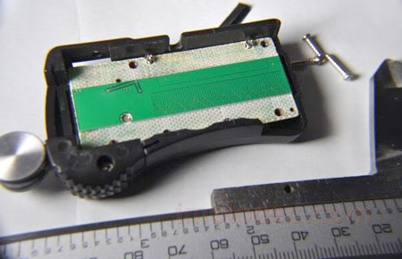
A little about the principle of operation of such caliper. It is capacious. No wheels that are spinning and measured moving the movable part is not. There is a control board located in the rolling part, on which conductors are applied to the type of rice in the usual caliper and similar conductive risks are on the line of the caliper. That is why the upper pad with numbers and divisions on the rail is not metallic, the response risks are hidden in it. These risks are at certain distances and when moving relative to each other, the capacity at different risks varies in different ways and the controller calculates these changes and ultimately receives information about the magnitude of the movement.
Then it is displayed on the screen.
Just below in the review there will be a disassembly of the calipers and you will see a fee with risks.
The final result of the operation of the instrument depends in addition to the quality of the manufacture of the material part of the caliper, which includes both the samples of the caliper and the electronics used, especially the analog part, and it is also from the firmware of the controller, which calculates the changes in the risks in risks and translates it into the length of movement.
The theory will return to practice.
Here are two small video With a demonstration of the work of the caliper:
Let's look it nowlet's see what's inside.

Here is the same fee with risks:

And here the controller, buttons, and LCD screen are visible:

Output: During the test, I did not notice any problems in the work of the caliper. The readings will not jump, multiple measurements of the same subject give an error of no more than one hundred. If not a sorry for money, it seems to me that it is not a bad purchase.
The goods are provided for writing a survey shop. The review is published in accordance with paragraph 18 of the site rules.
I plan to buy +8. Add to favourites I liked the review +25 +39The main defects of the channel tool, which can be eliminated during the repair, are errors in the fission of nonius, the curvature of the guide ribbing ribs, a pitching and skew frame, non-parallelism measuring surfaces, their damage, depreciation, etc.
Check the correctness of the ribs of the rod and measuring planes of sponges is made using blocks of terminal measures, clamping between measuring planes when the frame moves every 10 mm of the length of the rod. In any position on the rod, the force of pressing the measuring planes on the block should be the same on the entire plane measure. If the touch of measuring planes with any block of sharp and stupid sponges is different in different positions of the frame, it means that the rod is twisted. If, with any positions of the frame, the solution of sharp sponges is less than the solution of stupid or vice versa, then the sponges of the caliper is faulty.
To fix the bar, its working edge is checked on the paint on the check plate, and the bulges are removed to the personal file or finishing. Then the second rod rods make a strictly parallel working edge also with a file or refrigerated. After that, they make an adjustment of the measuring planes of sponges.
For their finishing, the caliper is fixed in tischs with lead sponges (Fig. 177, a). The finishes are made of cast-iron dying (Fig. 177, b). The prit is clamped between sponges, for which the frame is fed close to the tritution and fix the micrometric flow of the frame. Vitr must be moved forward and back and forth between sponges.

FIG. 177.
Advanced of the sponge of the caliper.
Sponge skews to install it is not difficult. To do this, it is enough to hold a block of end measures between the sponges and if one of the sides of the unit goes away from one of the sides of the sponges, then the skew is installed. Disamest of the workshop of sponges in relation to the rod is corrected by grinding on the plane oarsal machine. After grinding, the coarse paste of the gay is made at the same time sharp and stupid sponges and polishing them with glass trips with fine paste. The sponge finishes are considered to be completed if the prit is held with the same effort in both ends.
After tapping sponges, they check the coincidence of zero division of the rod with zero division of the Nonius. For this, the sponge is tightly shifted and pushed the movable frame of the caliper. Making sure that there is no lumen between the sponges, they free the screws that fasten the frame with nonius. Then we move the frame with the nonius in one or the other side with such a calculation so that the first and last division of the Nonius precisely coincided with the first and other appropriate division of the rod. Also draw attention to the fact that the second and third risks from the beginning of the nonius are located equally with the second and third risks from the end of the Nonius in relation to the relevant risks on the river. After that, the screws are fixed and, checking again the coincidence of divisions, the installation of the nonius is considered complete. In the event that when installing the nonius, it is not possible to move it due to the gap in the holes for the screws, the holes are expanded with the appropriate.
Very often there is a breakdown of the sponges of the caliper. When correcting this defect, one of the three solutions shown in FIG. 178: Crocheted the length of the sponges (Fig. 178, a), remove one pair of sponges (FIG. 178,6) or make a cut for inserting a new sponge (Fig. 178, B). Sometimes a new one is welded instead of the broken sponge.

FIG. 178.
Repair and restoration of sponges caliper.
The correction of defects in the veligor-type calipers is produced mainly by straightening with subsequent finishing of measuring planes. So, if, when the working surfaces of the sponges of the zero bar, the nonius does not coincide with the zero stroke of the bar, then after finishing the measuring planes, this error will be even more.
Therefore, it is corrected by straightening. The stationary sponge is put on the hardened bar, fortified in vice, and hit it in the place A (FIG. 179) so that its spout is going down. Strokes are produced on both sides of the caliper. The same is done with a sponge of a moving frame, hitting it in place b. The sharp ends of the sponges are rich in places a and b.

FIG. 179.
Repair of a lightweight velocked type (arrows show shock locations when straining).
After typing, the measuring planes are spilled and the measuring planes is brought to the coincidence of the divisions of the rod and the nonius, and in conclusion, the fears are cleaned and all planes are polished with shallow skin.
Correction of the base of the calibration is produced by ticking on the trigger plate using grinding powders.
The caliper was named thanks to the main element of his housing - a barbell, but the circus usual to us is a little far from this tool to their device. Understand the subject, full mysteries, we will try using this article, consider its device and the principle of work.
Device of the caliper - the main nodes and their purpose
The caliper device does not seem complicated, but its parts are so compact and optimally composed, which makes it a simple and easy to use. And it can do a lot, and the measurements that are performed with it are very important in many areas of industry and construction. When using the caliper, we get linear dimensions Objects such as external and internal. And the accuracy that in some models reaches an enviable level, makes this simple tool more and more in demand.
Purpose of the caliper - measurement of length, diameters, depth, and that is what it provides this opportunity, we will analyze on the example of the simple view of this device. The main node is a ruler, which is called a barbell, giving part of the name tool. The divisions on it are usually equal to 1 mm, and the total length is usually 15 cm, but separate models can be longer. The ruler determines maximum sizewhich will measure this tool. And therefore maximum length Or the diameter of the subject must be no more than 15 cm.
At the end of the line there are sponges, or rather than their halves, and the second half are located on a mobile frame, which moves along a ruler, measuring the size of the subject subject. The sponges are internal and external, the first cutters look outward, the second is on each other. Therefore, the first are inserted into the subject and are moved to fix the internal geometric parameterAnd the second are widely moved, and then come closer to fix the subject studied. To accurately remove the size or transfer it to another surface, the movable frame can be fixed with a special screw, which is on it.
On the main lineup, we can see the integer value of the desired size, but the nonical scale will help to clarify the result, which is applied to low part Frames to be exactly under the bulk of the line. There are ten divisions on Nonius, each of which squeezes 1.9 mm, the entire scale is 1.9 cm long. These are the parameters of the usual economic caliper, on other models, this ratio changes. Finding the division of Nonius, which coincides with any division of the main scale, you can clarify the desired value to the tenths of the millimeter. The use of the caliper is not limited to the inner and external size, you can mark the depth of the holes, for this there is a tail, which is extended from the ruler. This is a depth gauge scale.
Calcarcool - Classification and Marking
Measuring instrument The caliper can be 3 species and about 8 sizes, in any case, according to domestic regulatory documents. And important, buying any accurate instrument, focus on standards for which it is manufactured and calibrated. The species divide it depending on the indicator of the measured value from which we remove the desired figures. it there may be non-nonical (SCs), dials (Schurch) and digital (Shtsz) caliper. In the first case, we will have to spend on both scales with your eyes, consider divisions and report the result. In the second case, we will see the numbers on a mechanical scale with a movable arrow, but in the third case we will show a ready-made result on the display.
Inside the types of species can be separated by more subspecies depending on the design and length of the main line. For example, you can share the instruments of the material from which they are made. An example of a solid alloy tool can be STCT-I. There are differences in the device of sponges or additional devices. So, the SC-I and SC-III are distinguished by the location of the sponges, in the first case it is bilateral, and in the second one - one-sided. But in the SC-II there is a micrometric feed frame, which will make the markup easier if you need to carry your measurements to another plane. Differences on the sizes discuss for a long time does not make sense, it is worth only to say that the larger the line, the greater the error of the values \u200b\u200bobtained.
How to measure a caliper - instruction for beginners
Most technically developed people intuitively understand how to use the caliper, so we recall the highlights.
How to measure a caliper - step-by-step scheme
Step 1: Fastening Details
Check first the tool for goodness, for this twist the sponge without a detail to zero, look at the clearance, how correctly they are connected, and also look at the scale, the zeros coincided on two scales. After a positive result, you can proceed to work with the detail. It is most convenient to work in cases where the tool is in your right hand, and the measured item is in the left, or is completely fixed somewhere. If you are left-hand, the ratio is of course the opposite. For measuring external size Divide the sponges of the caliper, place the object between them and connect them. They must continue to the edges of the details surveyed. If it is solid, you can slightly squeeze the sponges for a dense touch. If the item is soft, do not do this, the results will be distorted.
The effort is controlled simply if you try to move the sponge with respect to the subject, then they should do it reluctantly, but if you also need an effort to do this, then you obviously changed.
Move the frame more comfortable with a thumb right hand, rest holding the bar. Check the position of the caliper relative to the subject, there is no distortion (the sponge should be at the same distance from the edge of the item on both sides), it is better to raise the design to the eye level. To see more clearly, the left hand is better to keep in the plane for the tool, and not before. Now neatly tighten the fastening screw, index and thumb, the remaining should continue to keep the bar. When the value is fixed, the part can be postponed and proceed to the study of the next step, how to measure the resulting number to the calipel.
Step 2: Remove the value
Reading readings are best at eye level. First of all, write the value of the main scale, i.e. integer. To do this, we are looking for a barcode on the main rod, which is located closest to the zero value of the nonius, this is an integer number of millimeters. You can remember, but you can burn yourself somewhere on the draft. Now we are looking for a barcode on Nonius, which is closest to his zero, but also exactly coincides with some division on the rod. Its sequence number should be multiplied by the price of the division of the nonius used (as a rule, 0.1 mm). If you are not sure that you know this value, look at the passport of this caliper.
Now it's small, just to summarize these numbers, and the result is ready. For example, on the rod, you had a value of 35 mm, and on Nonius counted 4 more divisions, then general value Equally 35.4 mm (3.54 cm). After work, the instrument is wiping (degreased), slightly spread the sponges (for a couple mm), weaken the clamp and laid into the case. If storage is planned long, then you can lubricate it against corrosion.
As you will see from this article, the modification of the electronic digital caliper is a very simple procedure, but it must be done carefully so as not to damage the tool. The design of the electronic caliper is provided 4 special contact. These contacts, for example, can be used to connect an external power source, functions control, etc.

Appointment of contacts Next (left to right): negative terminal, data, clock and positive terminal.
To activate the hidden options of the electronic digital caliper, it is necessary to connect the contacts 2 and 4 together.

Perhaps different electronic calipers have some differences, but in general their modification is carried out similarly.
The first step in revision is the search for screws fastening the housing. On our caliper, they are located under a plastic sticker. Their location can be seen in the photo.

After opening a plastic case containing a printed circuit board, a display and several metal elements, you need to unscrew several screws to extract pCB.
Special caution should be taken when handling pCB and display.
The display is connected to the printed circuit board by means of a conductive rubber gasket. Try not to disconnect the display from the board, because in this case, when assembling it will be quite difficult to align connections. And with incorrect location, there is a spontaneous disabling display and the appearance of strange characters on it.
After removing the electronic caliper printed circuit board, we get access to the right contacts.
Now you can solder 2 thin wires (the thinner, the better). One solder to contact number 2, and the other to the contact number 4.

To close these terminals, it is best to use a microcalization, for example from old computer mouse. The conclusions of the buttons must be bent at an angle of 90 º (as in the picture) so that it is tightly entered into the slot and, therefore, firmly held in place.

After turning the wires, the assembly of the electronic digital caliper is carried out in reverse order. After assembly from the nest must be stitching, soldered wires.
After that, we solder the button and place it in the slot.

Since the legs of the buttons were pre-bent, they spring up the button and it is firmly held in place. That's what it looks like.

When you press a new button, we get access to some modes that were previously not available.
When you first click the button, the electronic caliper goes to the quick read mode (FT), when you press the ZERO button, we can freeze the measured value (H).

When you press the button again, the electronic caliper will enter the minimum value mode (MIN). In this mode, the display shows the minimum measured value.
If you press the "ZERO" button again, go to the fixation mode of the measured value (H).
 Votes)
 How to return the love of her husband to his wife - Tips of the psychologist
 Why you can not give icons