Robot manipulator mechanical arm. Inexpensive robotic arm programmed in Arduino: a do-it-yourself robotic arm. Control program and explanations to it
This project is a multilevel modular task. The first stage of the project is the assembly of a robotic arm-manipulator module supplied as a set of parts. The second stage of the task will be the assembly of the IBM PC interface also from a set of parts. Finally, the third stage of the task is the creation of a voice control module.
The robot arm can be operated manually using the handheld remote control included in the kit. The robot arm can also be controlled either through a pre-assembled IBM PC interface or using a voice control module. The IBM PC interface kit allows you to control and program the robot's actions through an IBM PC work computer. The voice control device allows you to control the robot arm using voice commands.
All of these modules together form a functional device that will allow you to experiment and program automated sequences of actions or even “animate” a fully “wire-guided” arm.
The PC interface will allow you to program the manipulator arm for a chain of automated actions using a personal computer or "animate" it. There is also an option where you can control your hand interactively using either a hand controller or a Windows 95/98 program. The “animation” of the hand is the “entertaining” part of the chain of programmed automated actions. For example, if you put a baby glove doll on your manipulator arm and program the device to show a small show, then you will program the electronic doll to "animate". Automated action programming is widely used in industry and entertainment.
The most widely used robot in the industry is the robot arm. The robot arm is an extremely flexible tool, if only because the end segment of the arm manipulator can be the appropriate tool required for a particular task or production. For example, an articulated welding positioner can be used to spot welding, the spray nozzle can be used to paint various parts and assemblies, and the gripper can be used to clamp and set objects, just to name a few.
So, as we can see, the robot arm performs many useful functions and can serve ideal tool to study various processes. However, building a robotic arm from scratch is challenging. It is much easier to assemble a hand from the parts of a ready-made set. OWI sells reasonably good manipulator arm kits available from many distributors. electronic devices(see the list of parts at the end of this chapter). Using the interface, you can connect the assembled manipulator arm to the printer port of the work computer. As a working computer, you can use an IBM PC series or compatible machine that supports DOS or Windows 95/98.
Once connected to the computer's printer port, the manipulator arm can be operated interactively or programmatically from the computer. Interactive hand control is very simple. To do this, just click on one of the function keys to send the robot a command to perform a particular movement. Pressing the key a second time stops the execution of the command.
Programming a chain of automated actions is also easy. First click on the Program key to go to the program mode. In this mod, the hand functions in exactly the same way as described above, but in addition, each function and its time of action are recorded in a script file. The script file can contain up to 99 different functions, including pauses. The script file itself can be replayed 99 times. Writing various script files allows you to experiment with a computer-controlled sequence of automated actions and "revitalize" your hand. Working with the program under Windows 95/98 is described in more detail below. The Windows program is included in the robotic arm interface kit or can be downloaded free of charge from the Internet at http://www.imagesco.com.
In addition to the Windows program, the hand can be operated using BASIC or QBASIC. The DOS-level program is contained on the floppy disks included with the interface kit. However, the DOS program allows control only in interactive mode using the keyboard (see the printout of the BASIC program on one of the floppy disks). A DOS-level program does not allow the creation of script files. However, if you have experience in programming in BASIC, then the sequence of movements of the manipulator arm can be programmed similarly to the work of a script file used in a program under Windows. The sequence of movements can be repeated, as is done in many "animate" robots.
Robotic arm
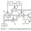
The manipulator arm (see Fig. 15.1) has three degrees of freedom of movement. The elbow joint can move vertically up and down in an arc of approximately 135 °. The shoulder joint moves the grip forward and backward in an arc of approximately 120 °. The arm can be rotated on the base clockwise or counterclockwise through an angle of approximately 350 °. The robot arm gripper can pick up and hold objects up to 5 cm in diameter and rotate around at the wrist joint by approximately 340 °.
Rice. 15.1. Kinematic diagram movements and turns of the robot arm
The OWI Robotic Arm Trainer used five miniature motors to propel the arm. direct current... The motors provide hand control with wires. This "wired" control means that each movement function of the robot (ie, the operation of the corresponding motor) is controlled by separate wires (voltage supply). Each of the five DC motors controls a different manipulator arm movement. Control by wire allows you to make the hand controller unit directly responsive to electrical signals. This simplifies the interface diagram of the robot arm that connects to the printer port.
The arm is made of lightweight plastic. Most of the parts bearing the main load are also made of plastic. The DC motors used in the arm design are miniature high-speed, low-torque motors. To increase the torque, each motor is connected to a gearbox. The motors, together with the gearboxes, are installed inside the structure of the manipulator arm. Although the gearbox increases torque, the robot arm cannot lift or carry heavy enough objects. The recommended maximum allowable lifting weight is 130g.
A kit for making a robot arm and its components are shown in Figures 15.2 and 15.3.

Rice. 15.2. Robot Arm Crafting Kit

Rice. 15.3. Gearbox before assembly
Motor control principle
To understand how Wired Control works, let's see how a digital signal drives a single DC motor. Two complementary transistors are required to control the motor. One transistor has PNP conductivity, the other is NPN conductivity respectively. Each transistor acts like an electronic switch, controlling the movement of the current flowing through the DC motor. The directions of current movement controlled by each of the transistors are opposite. The direction of the current determines the direction of rotation of the motor, respectively, clockwise or counterclockwise. In fig. 15.4 is a test circuit that you can build before making the interface. Note that when both transistors are turned off, the motor is off. Only one transistor should be turned on at a time. If, at some point, both transistors accidentally turn out to be open, then this will lead to a short circuit. Each motor is driven by two interface transistors that operate in a similar manner.

Rice. 15.4. Checker diagram
PC interface design
The PC interface diagram is shown in Fig. 15.5. The set of PC interface parts includes a printed circuit board, the location of the parts on which is shown in Fig. 15.6.

Rice. 15.5. Schematic diagram PC interface

Rice. 15.6. PC interface parts arrangement diagram
First of all, you need to determine the side of the PCB mounting. On the mounting side, white lines are drawn for resistors, transistors, diodes, ICs, and the DB25 connector. All parts are inserted into the board from the mounting side.
General note: After soldering the part to the PCB conductors, remove unnecessarily long leads from the print side. It is very convenient to follow a certain sequence when assembling parts. First, install the 100 kΩ resistors (color coded rings: brown, black, yellow, gold or silver) labeled R1-R10. Then mount the 5 diodes D1-D5, making sure that the black stripe on the diodes is opposite the DB25 connector, as shown by the white lines printed on the back side of the PCB. Then fit the 15K resistors (color coded, brown, green, orange, gold, or silver) labeled R11 and R13. In position R12, solder a red LED to the board. The anode of the LED corresponds to the hole under R12, indicated by the + sign. Then fit the 14- and 20-pin sockets under the U1 and U2 ICs. Mount and solder the DB25 elbow connector. Do not try to force the connector feet into the board too much, it requires extreme precision. If necessary, gently rock the connector, being careful not to bend the pins. Attach the slide switch and Type 7805 voltage regulator. Cut four lengths of wire and solder to the top of the switch. Observe the arrangement of the wires as shown in the figure. Insert and solder the TIP 120 and TIP 125 transistors. Finally, solder the eight-pin base / socket connector and the 75mm interconnect cable. The plinth is mounted so that the longest leads point upwards. Insert two ICs - 74LS373 and 74LS164 - into their respective sockets. Make sure that the position of the IC key on its cover matches the key marked with white lines on the PCB. You may have noticed that there is still space on the board for additional details... This place is for the network adapter. In fig. 15.7 shows a photograph of the finished interface from the mounting side.

Rice. 15.7. PC interface assembly. View from above
How the interface works
The manipulator arm has five DC motors. Accordingly, we need 10 I / O buses to control each motor, including the direction of rotation. The parallel (printer) port of IBM PC and compatible machines contains only eight I / O buses. To increase the number of control buses, the robot arm interface uses the 74LS164 IC, which is a serial-to-parallel converter (SIPO). With just two parallel buses, D0 and D1, that send the serial code to the IC, we can get eight additional I / O buses. As mentioned, you can create eight I / O buses, but this interface uses five of them.
When a serial code is input to the 74LS164 IC, the corresponding parallel code appears at the output of the IC. If the outputs of the 74LS164 were directly connected to the inputs of the control transistors, then the individual functions of the manipulator arm would be turned on and off in time with the sending of the serial code. Obviously, such a situation is unacceptable. To avoid this, the second IC 74LS373 is introduced into the interface circuit - a controlled eight-channel electronic key.
The 74LS373 eight-channel switch has eight input and eight output buses. Binary information present on the input buses is transmitted to the corresponding outputs of the IC only if the enable signal is applied to the IC. After switching off the enable signal, the current state of the output buses is retained (memorized). In this state, the signals at the input of the IC have no effect on the state of the output buses.
After the serial packet of information has been transmitted to the 74LS164 IC, an enable signal is sent to the 74LS373 IC from the D2 pin of the parallel port. This makes it possible to transfer information already in parallel code from the input of the 74LS174 IC to its output buses. The state of the output lines is respectively controlled by transistors TIP 120, which, in turn, control the functions of the manipulator arm. The process is repeated with each new command to the manipulator arm. The parallel bus buses D3-D7 drive directly the TIP 125 transistors.
Connecting the interface to the manipulator arm
The robotic arm is powered from a 6 V power supply, which consists of four D-elements located at the base of the structure. The PC interface is also powered from this 6V source. The power supply is bipolar and provides ± 3V. The interface is powered via an eight-pin Molex connector attached to the base of the pointing device.
Connect the interface to the manipulator arm using a 75mm 8-wire Molex cable. The Molex cable connects to a connector located at the base of the manipulator (see Figure 15.8). Check that the connector is inserted correctly and securely. To connect the interface board to the computer, use the 180 cm DB25 type cable provided in the kit. One end of the cable connects to the printer port. The other end connects to a DB25 connector on the interface board.

Rice. 15.8. Connecting the PC interface to the robot arm
In most cases, a printer is normally connected to the printer port. To avoid the hassle of plugging and unplugging connectors every time you want to use the pointing device, it is a good idea to purchase a two-position A / B Printer Bus Switch Box (DB25). Connect the keyer interface connector to Input A and the printer to Input B. You can now use the switch to connect the computer to either the printer or the interface.
Installing the program under Windows 95
Insert a 3.5 "floppy disk labeled" Disc 1 "into your floppy disk drive and run the setup program (setup.exe). The setup program will create a directory named" Images "on your hard disk and copy the necessary files into this directory. In the menu, the Images icon will appear.To start the program, click on the Images icon in the start menu.
Working with the program under Windows 95
Connect the interface to the printer port on the computer using a 180 cm DB 25 cable. Connect the interface to the base of the manipulator arm. Keep the interface off until a certain time. If the interface is turned on at this time, the information stored in the printer port may cause movements of the manipulator arm.
By double-clicking on the Images icon in the start menu, start the program. The program window is shown in Fig. 15.9. When the program is running, the red LED on the interface board should blink. Note: the interface does not need to be powered up for the LED to start blinking. The blinking speed of an LED is determined by the speed of your computer's processor. LED flicker may be very dim; in order to notice this, you may have to reduce the light in the room and fold your palms in a "ring" to observe the LED. If the LED does not blink, then the program may be accessing the wrong port address (LPT port). To switch the interface to a different port address (LPT port), go to the Printer Port Options box located in the upper right corner of the screen. Please choose a different option. Correct installation port address will cause the LED to flash.

Rice. 15.9. Screenshot of the PC interface program for Windows
When the LED is blinking, click on the Puuse icon and only then turn on the interface. Clicking the corresponding function key will trigger a reciprocal movement of the manipulator arm. Clicking again will stop the movement. Using the function keys to control your hand is called interactive fashion management.
Generating a script file
Script files are used to program movements and automated sequences of manipulator arm actions. The script file contains a list of temporary commands that control the movements of the manipulator arm. It is very easy to create a script file. To create a file, click on the program softkey. This operation will allow you to enter the fashion of "programming" the script file. By pressing the function keys, we will control the movements of the hand, as we have already done, but the command information will be written to the yellow script table located in the lower left corner of the screen. The step number, starting with one, will be indicated in the left column, and for each new command it will increase by one. The type of movement (function) is indicated in the middle column. After clicking the function key again, the execution of the movement is terminated, and the value of the time of execution of the movement from its beginning to the end appears in the third column. The movement time is indicated with an accuracy of a quarter of a second. Continuing in the same way, the user can program up to 99 movements into a script file, including pauses in time. Then the script file can be saved, and later loaded from any directory. Execution of script-file commands can be cyclically repeated up to 99 times, for which it is necessary to enter the number of repetitions in the Repeat window and press Start. Press the Interactive key to end writing to the script file. This command will bring the computer back to online mode.
"Animation" of objects
Script files can be used for computerized automation of actions or for "animating" objects. In the case of "animating" objects, the controlled robotic mechanical "skeleton" is usually covered with an outer shell and is not visible itself. Remember the glove doll from the beginning of the chapter? The outer shell can be in the form of a person (partially or completely), an alien, an animal, a plant, a stone and anything else.
Limitations of the scope
If you want to achieve a professional level of performing automated actions or "animating" objects, then, so to speak, to maintain the brand, the positioning accuracy when performing movements at each moment of time should be close to 100%.
However, you may notice that as you repeat the sequence of actions written in the script file, the position of the manipulator arm (pattern movement) will differ from the original one. This happens for several reasons. As the batteries of the manipulator arm power supply are discharged, a decrease in the power supplied to DC motors results in a decrease in the torque and rotation speed of the motors. Thus, the length of movement of the manipulator and the height of the lifted load for the same period of time will differ for dead and "fresh" batteries. But this is not the only reason. Even with a stabilized power supply, the engine speed will change since there is no engine speed governor. For each fixed period of time, the number of revolutions will be slightly different each time. This will lead to the fact that each time the position of the manipulator arm will be different. On top of that, there is a certain amount of play in the gears of the gearbox, which is also not taken into account. Under the influence of all these factors, which we have considered in detail here, when executing a loop of repetitive commands in a script file, the position of the manipulator arm will differ slightly each time.
Home position search
You can improve the performance of the device by adding a feedback circuit that monitors the position of the pointing arm. This information can be entered into a computer to determine the absolute position of the manipulator. With such a positional feedback system, it is possible to set the position of the manipulator arm to the same point at the beginning of the execution of each sequence of commands written in the script file.
There are many possibilities for this. In one of the main methods, positional control at each point is not provided. Instead, a set of limit switches are used that correspond to the original "start" position. The limit switches only determine exactly one position - when the manipulator reaches the "start" position. To do this, it is necessary to set the sequence of the limit switches (buttons) so that they close when the manipulator reaches the end position in one direction or another. For example, one limit switch can be installed on the base of the manipulator. The switch should only operate when the manipulator arm reaches its end position when turned clockwise. Other limit switches must be installed at the shoulder and elbow joints. They should work with full extension of the corresponding joint. Another switch is installed on the hand and is triggered when the hand is turned fully clockwise. The last limit switch is installed on the gripper and closes when it is fully opened. To put the manipulator in its original position, every possible movement of the manipulator is carried out in the direction necessary to close the corresponding limit switch until this switch is closed. Once the starting position for each movement has been reached, the computer will accurately "know" the true position of the manipulator arm.
After reaching the initial position, we can restart the program written in the script file, under the assumption that the positioning error during the execution of each cycle will accumulate rather slowly, which will not lead to too large deviations of the position of the manipulator from the desired one. After executing the script file, the hand is set to its original position, and the cycle of the script file is repeated.
In some sequences, knowledge of only the starting position turns out to be insufficient, for example, when raising an egg without the risk of crushing its shell. In such cases, a more sophisticated and accurate positional feedback system is needed. The signals from the sensors can be processed using an ADC. The received signals can be used to determine the values of parameters such as position, pressure, speed and torque. The following simple example can be used as an illustration. Imagine that you have attached a small linear variable resistor to the capture assembly. The variable resistor is installed in such a way that moving its slider back and forth is associated with the opening and closing of the gripper. Thus, depending on the degree of opening of the gripper, the resistance of the variable resistor changes. After calibration, by measuring the current resistance of the variable resistor, you can accurately set the opening angle of the gripper clamps.
The creation of such a feedback system introduces another level of complexity into the device and, accordingly, leads to its rise in price. Therefore, more simple option is the introduction of the system manual control to correct the position and movements of the manipulator arm during the execution of the script program.
Manual interface control system
Once you have verified that the interface is working properly, you can use the 8-pin flat connector to connect the handheld terminal to it. Check the position of the Molex 8-pin connector to the head of the connector on the interface board as shown in fig. 15.10. Insert the connector carefully until it is firmly seated. After that, the manipulator arm can be operated from the hand-held remote control at any time. It doesn't matter if the interface is connected to a computer or not.

Rice. 15.10. Manual control connection
DOS keyboard control program
There is a DOS program that allows you to interactively control the work of the manipulator hand from the computer keyboard. The list of keys corresponding to the performance of a particular function is given in the table.

In the voice control of the manipulator arm, a speech recognition set (URR) is used, which was described in Ch. 7. In this chapter, we will make an interface that connects the URR with the manipulator arm. This interface is also offered as a kit by Images SI, Inc.
The interface diagram for the URR is shown in Fig. 15.11. The interface uses a 16F84 microcontroller. The microcontroller program looks like this:
‘URR interface program
Symbol PortA = 5
Symbol TRISA = 133
Symbol PortB = 6
Symbol TRISB = 134
If bit4 = 0 then trigger 'If writing to the trigger is enabled, read the
Goto start 'Repetition
pause 500 'Wait 0.5 s
Peek PortB, B0 'Read BCD code
If bit5 = 1 then send ‘Output code
goto start 'Repetition
peek PortA, b0 'Read port A
if bit4 = 1 then eleven 'Is there 11?
poke PortB, b0 'Output code
goto start 'Repetition
if bit0 = 0 then ten
goto start 'Repetition
goto start 'Repetition

Rice. 15.11. URR controller circuit for a robot arm
The software update for 16F84 can be downloaded free of charge from http://www.imagesco.com
URR interface programming
The programming of the URR interface is similar to the programming procedure of the URR from the set described in Ch. 7. For correct work of the manipulator arm, you must program the command words according to the numbers corresponding to the specific movement of the manipulator. Table 15.1 shows examples of command words that control the operation of the manipulator arm. You can choose the command words to your liking.
Table 15.1
PC Interface Parts List
(5) NPN transistor TIP120
(5) PNP transistor TIP 125
(1) IC 74164 code converter
(1) IC 74LS373 eight keys
(1) LED red
(5) Diode 1N914
(1) Molex 8-pin female connector
(1) Molex cable, 8-core, 75 mm long
(1) DIP switch
(1) DB25 Angle Connector
(1) 1.8m DB 25 cable with two M-type connectors.
(3) Resistor 15 kΩ, 0.25 W
All parts listed are included in the kit.
Parts List for Speech Recognition Interface
(5) NPN transistor TIP 120
(5) PNP transistor TIP 125
(1) IC 4011 NOR gate
(1) IC 4049 - 6 buffers
(1) IC 741 operational amplifier
(1) Resistor 5.6 kΩ, 0.25 W
(1) Resistor 15 kΩ, 0.25 W
(1) 8-pin Molex connector head
(1) Molex cable, 8 cores, 75 mm long
(10) Resistor 100 kΩ, 0.25 W
(1) Resistor 4.7 kOhm, 0.25 W
(1) 7805 voltage regulator IC
(1) PIC IC 16F84 microcontroller
(1) 4.0 MHz crystal resonator
Hand arm interface kit
OWI Manipulator Arm Kit
Speech recognition interface for the manipulator arm
Speech Recognition Device Set
Parts can be ordered from:
Images, SI, Inc.
Connection:
If you have assembled the parts of the manipulator in accordance with the instructions, then you can start assembling electronic circuit... We propose to connect the servos of the manipulator to the Arduino UNO via the Trerma-Power Shield, and control the servos using the Trema potentiometers.
- Turning the knob of the first Trema potentiometer will turn the base.
- Turning the knob of the second Trema potentiometer will turn the left shoulder.
- Turning the knob of the third Trema potentiometer will turn the right shoulder.
- Turning the knob of the fourth Trema potentiometer will set the gripper in motion.
The program code (sketch) provides for the protection of servo drives, which consists in the fact that the range of their rotation is limited by the interval (two angles) of the free wheeling. The minimum and maximum angles of rotation are specified as the last two arguments to the map () function for each servo. And the value of these angles is determined during the calibration process, which must be performed before starting to work with the manipulator.
Program code:
If you apply power before calibration, the arm may not move properly! Complete all calibration steps first.
#include
Calibration:
Before you start working with the manipulator, you need to calibrate it!
- Calibration consists in specifying the extreme values of the angle of rotation for each servo, so that the parts do not interfere with their movements.
- Disconnect all servos from the Trema-Power Shield, upload your sketch and power up.
- Open the serial port monitor.
- The monitor will display the angles of rotation of each servo (in degrees).
- Connect the first servo (base rotation) to D10.
- Turning the knob of the first Trema potentiometer (pin A2) will turn the first servo (pin D10), and the value of the current angle of this servo will change in the monitor (value: A1 = ...). The extreme positions of the first servo will be in the range from 10 to 170 degrees (as written in the first line of the loop code). This range can be changed by replacing the values of the last two arguments to the map () function in the first line of loop code with new ones. For example, replacing 170 with 180, you will increase the extreme position of the servo in this direction. And by replacing 10 with 20, you will decrease the other extreme position of the same servo.
- If you changed the values, then you need to reload the sketch. Now the servo will turn within the new, set by you, limits.
- Connect the second servo (controlling the left shoulder rotation) to pin D9.
- Turning the knob of the second Trema potentiometer (pin A3) will turn the second servo (pin D9), and the value of the current angle of this servo will change in the monitor (value: A2 = ...). The extreme positions of the second servo will be in the range from 80 to 170 degrees (as written in the second line of the loop sketch code). This range changes in the same way as for the first servo.
- If you changed the values, then you need to reload the sketch.
- Connect the third servo (controlling the rotation of the right shoulder) to pin D8. and calibrate it in the same way.
- Connect the fourth servo (control servo) to D7. and calibrate it in the same way.
It is enough to perform the calibration once, after assembling the manipulator. The changes you made (the values of the limit angles) will be saved in the sketch file.
This article is an introductory guide for beginners to create robotic arms that are programmed with Arduino. The concept is that the robotic arm design will be inexpensive and easy to assemble. We will put together a simple prototype with code that can and should be optimized, this will be a great start for you in robotics. The Arduino robot arm is controlled by a hacked joystick and can be programmed to repeat the sequence of actions you specify. If you are not good at programming, then you can take up the project as a training in assembling hardware, pour my code into it and get basic knowledge on its basis. Again, the project is quite simple.
The video shows a demo with my robot.
Step 1: List of materials


We need:
- Arduino board. I've used Uno, but any of the flavors will do the job just as well.
- Servos, the 4 cheapest you'll find.
- Materials for the body of your choice. Wood, plastic, metal, cardboard will do. My project is built from an old notepad.
- If you don't want to bother with the PCB, then you need a breadboard. The board will do small size, look for options with jumpers and a power supply - they are quite cheap.
- Something for the base of the hand - I used a coffee can, which is not the best option, but that's all I could find in the apartment.
- Fine thread for the arm mechanism and a needle for making holes.
- Glue and duct tape to hold it together. There is nothing that cannot be held together with duct tape and hot glue.
- Three 10K resistors. If you do not have resistors, then there is a workaround in the code for such cases, however the best option will buy resistors.
Step 2: how it works


The attached figure shows the principle of the hand. I will also explain everything in words. The two parts of the hand are connected by a thin thread. The middle of the thread is connected to the hand servo. When the servo pulls the thread, the hand contracts. I fitted my arm with a ballpoint spring, but if you have a more flexible material you can use it.
Step 3: modifying the joystick

Assuming you've already finished assembling the arm mechanism, I'll move on to the joystick part.
An old joystick was used for the project, but in principle any device with buttons will do. Analog buttons (mushrooms) are used to control servos, since in essence they are just potentiometers. If you don't have a joystick, you can use the three normal potentiometers, but if you, like me, modify the old joystick yourself, then here's what you need to do.
I connected the potentiometers to the breadboard, each of them has three terminals. One of them needs to be connected to GND, the second to + 5V to the Arduino, and the middle one to the input, which we will define later. We won't be using the Y-axis on the left potentiometer, so we only need the potentiometer above the joystick.
As for the switches, connect + 5V to one end, and the wire that goes to the other input of the Arduino to the other end. My joystick has a common + 5V line for all switches. I connected only 2 buttons, but then connected another one as it became necessary.
It is also important to cut the wires that go to the chip (black circle on the joystick). When you complete all of the above, you can start wiring.
Step 4: Wiring our device

The photo shows the wiring of the device. Potentiometers are levers on the joystick. Elbow is the right Y axis, Base is the right X axis, Shoulder is the left X axis. If you want to reverse the direction of movement of the servos, simply change the position of the + 5V and GND wires on the corresponding potentiometer.
Step 5: Download the code
At this stage, we need to download the attached code to the computer and then upload it to the Arduino.
Note: if you have already downloaded the code to Arduino before, then just skip this step - you will not learn anything new.
- Open IDE Arduino and paste the code into it
- In Tools / Board select your board
- In Tools / Serial Port select the port to which your board is connected. Most likely, the selection will consist of one item.
- Click the Upload button.
You can change the range of the servos, in the code I left notes on how to do this. Most likely, the code will work without problems, you only need to change the parameter of the hand servo. This parameter depends on how you set up the thread, so I recommend choosing it exactly.
If you do not use resistors, then you will need to modify the code in the place where I left notes about it.
Files
Step 6: launch the project
The robot is controlled by movements on the joystick, the hand is clenched and unclenched using the hand button. The video shows how everything works in real life.
Here's a way you can program your hand:
- Open the Serial Monitor in Arduino IDE, this will make it easier to monitor the process.
- Save the starting position by clicking Save.
- Move only one servo at a time, for example, Shoulder up, and press save.
- Activate the hand also only at its step, and then save by pressing save. Deactivation is also performed in a separate step, followed by pressing save.
- When you finish the sequence of commands, press the play button, the robot will move to the starting position and then begin to move.
- If you want to stop it, unplug the cable or press the reset button on the Arduino board.
If you did everything correctly, the result will be similar to this one!
I hope this tutorial was useful to you!
One of the main driving forces automation of modern production are industrial robotic manipulators. Their development and implementation made it possible for enterprises to reach a new scientific and technical level of performing tasks, redistribute responsibilities between technology and humans, and increase productivity. We will talk about the types of robotic assistants, their functionality and prices in the article.
Assistant # 1 - robotic arm
Industry is the foundation of most of the world's economies. The income of not only a single production unit, but also the state budget depends on the quality of the offered goods, volumes and pricing.
In light of the active introduction of automated lines and the widespread use of smart technology, the requirements for the supplied products are increasing. It is almost impossible to withstand the competition without the use of automated lines or industrial robotic manipulators.
How an industrial robot works
The robot arm looks like a huge automated "hand" under the control of an electrical control system. There is no pneumatics or hydraulics in the design of the devices, everything is built on electromechanics. This reduced the cost of robots and increased their durability.

Industrial robots can be 4-axis (used for stacking and packing) and 6-axis (for other types of work). In addition, robots differ depending on the degree of freedom: from 2 to 6. The higher it is, the more accurately the manipulator recreates the movement of a human hand: rotation, movement, squeezing / unclenching, tilting, etc.
The principle of operation of the device depends on its software and equipment, and if at the beginning of its development the main goal was to free workers from heavy and dangerous work, today the range of tasks performed has increased significantly.

The use of robotic assistants allows you to cope with several tasks simultaneously:
- reduction of working areas and the release of specialists (their experience and knowledge can be used in another area);
- increase in production volumes;
- improving product quality;
- due to the continuity of the process, the production cycle is shortened.
In Japan, China, USA, Germany, a minimum of employees work at factories, whose duty is only to control the operation of manipulators and the quality of manufactured products. It should be noted that industrial robot-manipulator is not only a functional assistant in mechanical engineering or welding. Automated devices are presented in a wide range and are used in metallurgy, light and Food Industry... Depending on the needs of the enterprise, you can choose a manipulator that matches the functional responsibilities and budget.
Types of industrial robotic manipulators
Today there are about 30 types of robotic arms: from universal models to highly specialized assistants. Depending on the functions performed, the mechanisms of manipulators may differ: for example, it can be welding, cutting, drilling, bending, sorting, stacking and packaging goods.

Unlike the existing stereotype about the high cost of robotic technology, every, even a small enterprise, will be able to purchase such a mechanism. Small universal robotic manipulators with a low load capacity (up to 5 kg) ABB, and FANUC will cost from 2 to 4 thousand dollars.
Despite the compactness of the devices, they are able to increase the speed of work and the quality of product processing. A unique software will be written for each robot, which precisely coordinates the operation of the unit.
Highly specialized models
Welding robots have found their greatest application in mechanical engineering. Due to the fact that the devices are able to weld not only smooth parts, but also effectively carry out welding work at an angle, in hard-to-reach places install entire automated lines.

A conveyor system is launched, where each robot does its part of the work for a certain time, and then the line begins to move to the next stage. Organizing such a system with people is not easy enough: none of the workers should be absent for a second, otherwise the entire production process gets lost, or a marriage appears.
Welders
The most common options are welding robots. Their productivity and accuracy are 8 times higher than that of humans. Such models can perform several types of welding: arc or spot (depending on the software).

Kuka industrial robotic manipulators are considered to be the leaders in this field. The cost is from 5 to 300 thousand dollars (depending on the carrying capacity and functions).
Pickers, movers and packers
Heavy and harmful for human body labor was the reason for the emergence of automated assistants in this industry. Packing robots prepare goods for shipment in minutes. The cost of such robots is up to 4 thousand dollars.

Manufacturers ABB, KUKA, and Epson offer the use of devices for lifting heavy loads weighing more than 1 ton and transporting from the warehouse to the place of loading.
Industrial robot manipulator manufacturers
Japan and Germany are considered the undisputed leaders in this industry. They account for more than 50% of all robotic technology. It is not easy to compete with the giants, however, in the CIS countries their own manufacturers and start-ups are gradually appearing.

KNN Systems. The Ukrainian company is a partner of the German Kuka and is developing projects for the robotization of welding, milling, plasma cutting and palletizing processes. Thanks to their software, the industrial robot can be reconfigured for the new kind tasks in just one day.

Rozum Robotics (Belarus). The company's specialists have developed an industrial robotic arm PULSE, which is distinguished by its lightness and ease of use. The device is suitable for assembling, packing, gluing and rearranging parts. The price of the robot is around $ 500.
"ARKODIM-Pro" (Russia). It is engaged in the production of linear robotic manipulators (move along linear axes) used for injection molding of plastic. In addition, ARKODIM robots can work as part of a conveyor system and act as a welder or packer.
Of the features of this robot on the Arduino platform, one can note the complexity of its design. The robotic arm consists of many levers that allow it to move in all axes, grab and move various things using just 4 servo motors. Gathering with my own hands such a robot, you will definitely be able to surprise your friends and loved ones with possibilities and a pleasant view this device! Remember that you can always use our graphic environment RobotON Studio for programming!
If you have any questions or comments, we are always in touch! Create and share your results!
Peculiarities:
To assemble a robotic arm with your own hands, you will need quite a few components. The main part is occupied by 3D printed parts, there are about 18 pieces (printing the slide is optional). If you downloaded and printed everything you need, then you will need bolts, nuts and electronics:
- 5 bolts M4 20mm, 1 x 40mm and corresponding nuts with anti-twist protection
- 6 bolts M3 10mm, 1 x 20mm and corresponding nuts
- Breadboard with connecting wires or shield
- Arduino Nano
- 4 servo motors SG 90
After assembling the body, it is IMPORTANT to make sure it is free to move. If the key nodes of the Robohand are difficult to move, the servo motors may not be able to handle the load. When assembling the electronics, it must be remembered that it is better to connect the circuit to the power supply after a complete check of the connections. To avoid damage to the SG 90 servo drives, you do not need to turn the motor by hand if not necessary. If you need to develop SG 90, you need to smoothly move the motor shaft in different directions.
Specifications:
- Simple programming due to the presence of a small number of motors, and of the same type
- Dead spots for some servo drives
- Wide applicability of the robot in daily life
- Interesting engineering work
- The need to use a 3D printer
 Automation of control of the tightness of the purge valve of the gas manifold of boiler plants
 Useful information about installing air conditioners with your own hands
 Site drainage project: selection of location, slope, depth, drainage system elements