Legend on the map. Classification of conventional signs. The location and actions of units
Symbols of topographic maps give complete information about the area. They are generally accepted and are used for topographic maps and plans. Topographic maps are important material not only for tourists, but also for geodetic organizations, for authorities that are engaged in planning the area and transferring the boundaries of sites.
Knowledge about conventional signs helps not only to read the map correctly, but also to draw up detailed plans of the area, taking into account the new objects that have appeared.
Topographic maps are a kind of geographic maps. They carry detailed information about the terrain plan, indicating the location of various technical and natural objects relative to each other.
Topographic maps vary in scale of execution. All of them carry less or more detailed information about the area.
The scale of the map is indicated on the side or bottom of the map. It shows the ratio of sizes: indicated on the map to natural. Thus, the larger the denominator, the less detailed the material. Let's say a map 1:10 000 will have 100 meters in 1 centimeter. To find out the distance in meters between objects, using a ruler, the segment between two points is measured and multiplied by the second indicator.

- The most detailed is the topographic plan of the area, its scale is 1: 5,000 inclusive. It does not count as a map and is not as accurate as it does not take into account the notion that the earth is round. This somewhat distorts its informativeness, nevertheless, the plan is indispensable when depicting cultural, household and economic objects. In addition, the plan can also show micro-objects that are difficult to find on the map (for example, vegetation and soils, the contours of which are too small to be depicted in other materials).
- Topographic maps in scale 1:10 000 and 1:25 000 are considered the most detailed among the maps. They are used for household needs. They depict settlements, industrial and agricultural facilities, roads, hydrographic networks, swamps, fences, borders, etc. Such maps are most often used to obtain information about objects in an area that does not have significant forest cover. The objects of management are most reliably depicted in them.
- Maps with a scale of 1: 50,000 and 1: 100,000 are less detailed. They schematically depict the outlines of forests and other large objects, the image of which does not require much detail. Such maps are useful for aeronautical navigation, road routes and so on.
- Less detailed maps are used for military purposes to accomplish assigned planning tasks for various operations.
- Maps with a scale of up to 1: 1,000,000 allow you to correctly assess the overall picture of the area.
Having decided on the task at hand, the choice of material seems to be absolutely not a difficult task. Depending on how much detailed information about the area is needed, the required map scale is also selected.
Working with a topographic map requires a clear knowledge of the schematic designation of the depicted objects.
Types of conventional symbols:
- areal (large-scale) - for large objects (forest, meadow, lake), their sizes can be easily measured on a map, correlated with a scale and get the necessary information about the depth, length, area;
- linear - for extended geographic objects, the width of which cannot be indicated, they are plotted as a line corresponding to the scale in order to correctly display the length of the object (road, power strip);
- off-scale - they are used to designate strategically important objects, without which the map will be incomplete, but in a rather arbitrary size (bridge, well, separate tree);
- explanatory - characterizing the object, for example, the depth of the river, the height of the slope, the tree, which denotes the type of forest;
- depicting landscape components: relief, rocks and stones, hydrographic objects, vegetation, artificial structures;
- special - are applied to maps for individual sectors of the economy (meteorological, military signs).
- the main information that the image of a settlement carries is the density of buildings and the placement of the boundaries of the object, for this it is not necessary to mark each building, you can limit yourself to the main streets, intersections and important buildings;
- the legend of a group of homogeneous objects allows the image of only the extreme of them;
- when drawing a line of roads, it is necessary to indicate their middle, which should correspond to the situation on the ground, and the width of the message object itself should not be displayed;
- strategically important sites such as factories and factories are marked on the spot where the main building or factory chimney is located.
Due to the correct application of signs on the map, you can get a detailed idea of the relative position of objects on the ground, the distance between them, their heights, depths and other important information.
The map must be objective and this requirement includes the following provisions:

- correctly selected standard symbols, if this is a special map, then the symbols should also be generally known in a certain area;
- correct image of line elements;
- one map must be drawn in the same image style;
- micro-objects must also be indicated exactly, if there are a certain number of such objects of the same size on the ground, they must all be marked with the same sign on the map;
- the color indicators of the elements of relief forms must be maintained correctly - the heights and lowlands are often depicted in paints, there should be a scale next to the map that shows what height on the terrain a particular color corresponds to.
Symbols of topographic maps and plans are applied in accordance with uniform rules.
So:- The sizes of objects are displayed in millimeters. These signatures are usually placed to the left of conventional signs. For one object, two numbers are given for the height and width. If these parameters match, one signature is allowed. For round objects, their diameter is indicated, for signs in the shape of a star - the diameter of the circumscribed circle. For an equilateral triangle, the parameter of its height is given.
- The thickness of the lines should correspond to the scale of the map. The main objects of plans and detailed maps (factories, mills, bridges, sluices) are drawn with 0.2–0.25 mm lines, the same designations on small-scale maps from 1:50 000 - with 0.2 mm lines. Lines for secondary characters are 0.08–0.1 mm thick. On plans and large-scale maps, an increase in signs by one third is allowed.
- The legend of topographic maps must be clear and readable, the spaces between the inscriptions must be at least 0.2–0.3 mm. Strategically important objects can be slightly increased in size.
Separate requirements are put forward for the color scheme.
So, the background color should provide good readability, and the conventional signs are indicated by the following colors:
- green - designations of glaciers, permanent snow, swamps, salt marshes, intersections of coordinate lines and hydrography;
- brown - relief forms;
- blue - water bodies;
- pink - interline gaps of the highway;
- red or brown - some signs of vegetation;
- black - shading and all signs.
- Objects indicated by off-scale conventional symbols on topographic maps and plans must correspond to the location on the ground. To do this, they need to be placed according to certain rules.
- the center of the sign of regular-shaped objects (round, square, triangular) on the plan;
- the middle of the base of the symbol - for perspective displays of objects (lighthouses, rocks);
- vertices of the corner of the designation - for icons with an element of right angles (tree, pillar);
- the middle of the bottom line of the sign - for designations in the form of a combination of figures (towers, chapels, towers).
Knowledge of the correct placement and application of signs will help to correctly draw up a topographic map or a plan of the area, making them understandable to other users.
The symbolic designation of groups of objects should be done according to the rules below.

- Geodetic points. These objects should be marked in as much detail as possible. The marks of the centers of points are applied exactly to the centimeter. If the point is located in an elevated area, it is necessary to note the height of the hillock or mound. When drawing the boundaries of land surveys, which are marked with pillars and numbered on the ground, the numbering should also be displayed on the map.
- Buildings and their parts. Building contours should be mapped in accordance with the building layout and dimensions. The most detailed depictions of multi-storey and historically important buildings. The number of storeys is indicated starting from two floors. If the building has an orientation tower, it must also be displayed on the map.
Small buildings, such as pavilions, cellars, building elements, are displayed at the request of the customer and only on detailed maps. Building numbers are reproduced only on large maps. Additionally, letters can denote the materials from which the building is built, its purpose, fire resistance.
Conventional signs are used to distinguish buildings under construction or dilapidated, cultural and religious buildings. Objects on the map should be placed exactly as in reality.
In general, the detail and detail of the description of the characteristics depends on the purpose of drawing up the map and is negotiated by the customer and the contractor.
- Industrial facilities. The number of storeys in buildings does not matter. More important objects are administrative buildings and pipes. For pipes over 50 meters, the actual height must be signed.
At enterprises that have mines and are engaged in the extraction of minerals, it is customary to designate objects located on the surface. The mapping of underground tracks is carried out as agreed with the customer, indicating the working and non-working branches. For quarries, a numerical designation of their depth is mandatory.
- Railways are shown with their gauge designation. Inactive roads should also be marked on maps. For electrified roads and tramways, a power line must be displayed nearby.
The map contains the designation of the slopes of roads, embankments and their height, slopes, tunnels and their characteristics. Dead ends, turning circles and road endings are required.
Roads are marked with a certain sign, which depends on the surface. The carriageway must be highlighted with a line.
- It is customary to divide hydrographic objects into three groups:
- permanent;
- indefinite - existing all the time, but whose outlines often change;
- non-permanent - changing depending on the season, but with a pronounced source and direction of the channel.
Permanent water bodies are depicted by solid lines, the rest - by dash-dotted lines.
- Relief. When depicting the terrain, horizontals or contour lines are used, indicating the heights of individual ledges. Moreover, lowlands and elevations are depicted similarly, using strokes: if they go outward, then an elevation is depicted, if inward it is a depression, gully or lowland. In addition, if the contour lines are close to each other, the slope is considered steep, if far - gentle.
A good topographic map must be extremely accurate, objective, complete, reliable, and clearly delineate the contours of objects. When drawing up a map, it is necessary to take into account the requirements of the customer.
Depending on the purposes for which the topographic map is intended, some simplifications or insignificant distortions of minor objects are allowed, but general requirements must be observed.
All objects on the ground, the situation and characteristic landforms are displayed on topographic plans with conventional symbols.
Legend for topography
There are four main types into which conventional signs are subdivided:
- Explanatory captions.
- Linear symbols.
- Areal (contour).
- Out of scale.
Explanatory captions are used to indicate additional characteristics of the depicted objects: the speed of the current and its direction are signed at the river, at the bridge - the width, length and its carrying capacity, at the roads - the nature of the coverage and the width of the carriageway itself, etc.
Linear conventional signs (designations) are used to display linear objects: power lines, roads, product pipelines (oil, gas), communication lines, etc. The width shown on the topographic plan of linear objects is off-scale.
Contour or area conventional symbols represent those objects that can be displayed in accordance with the scale of the map and occupying a certain area. The contour is drawn with a thin solid line, dashed or depicted as a dotted line. The formed contour is filled with conventional symbols (meadow vegetation, arboreal, garden, vegetable garden, bushes, etc.).
To display objects that cannot be expressed on the scale of the map, out-of-scale conventional symbols are used, while the location of such an out-of-scale object is determined by its characteristic point. For example: the center of a geodetic point, the base of a kilometer pole, the centers of radio, TV towers, pipes of factories and plants.
In topography, the objects displayed are usually divided into eight main segments (classes):
- Relief
- Mathematical basis
- Soils and vegetation
- Hydrography
- Road network
- Industrial enterprises
- Settlements,
- Signatures and borders.
Collections of conventional symbols for maps and topographic plans of various scales are created in accordance with this division into objects. Approved by the state. bodies, they are the same for all topographic plans and are required when drawing any topographic surveys (topographic surveys).
Frequently encountered conventional signs on topography:
Points of state geodetic network and points of concentration
 - Land use and allotment boundaries with boundary marks at turning points
 - Buildings. The numbers indicate the number of storeys. Explanatory captions are given to indicate the fire resistance of the building (w - non-fire-resistant residential (wooden), n - non-residential non-fire-resistant, kn - non-residential stone, kzh - residential stone (usually brick), SMZ and SMN - mixed residential and mixed non-residential - wooden buildings with thin cladding brick or with floors built from different materials (the first floor is brick, the second is wooden)). A building under construction is shown with a dotted line.
 - Slopes. Used to display ravines, road embankments and other artificial and natural landforms with sharp elevation changes
 - Poles of power lines and communication lines. The legend follows the cross-sectional shape of the column. Round or square. Reinforced concrete pillars have a dot in the center of the symbol. One arrow in the direction of the electric wires - low-voltage, two - high-voltage (6 kV and above)
 - Underground and overhead communications. Underground - dotted line, aboveground - solid. The letters indicate the type of communication. K - sewerage, G - gas, N - oil pipeline, V - water supply, T - heating main. Additional explanations are also given: The number of wires for cables, the pressure of the gas pipeline, the material of the pipes, their thickness, etc.
 - Various areal objects with explanatory captions. Wasteland, arable land, construction site, etc.
 - Railways
 - Car roads. The letters indicate the coating material. A - asphalt, Sch - crushed stone, C - cement or concrete slabs. On dirt roads, the material is not indicated, and one of the sides is shown with a dotted line.
 - Wells and wells
 - Bridges over rivers and streams
 - Horizontals. Serve to display the terrain. They are lines formed when the earth's surface is cut by parallel planes at equal intervals of height change.
 - Elevations of the heights of the characteristic points of the terrain. Typically in the Baltic system of heights.
 - Various woody vegetation. The predominant tree species, the average height of trees, their thickness and the distance between trees (density) are indicated
 - Free standing trees
 - Shrubs
 - Various meadow vegetation
 - Boggy with reed vegetation
 - Fences. Fences are stone and reinforced concrete, wooden, picket fence, netting, etc.
Commonly used abbreviations in topography:
Buildings:
H - Non-residential building.
F - Residential.
KN - Stone non-residential
KZh - Stone residential
PAGE - Under construction
FUND. - Foundation
SMN - Mixed non-residential
SMZH - Mixed Residential
M. - Metallic
development - Destroyed (or fallen apart)
gar. - Garage
T. - Toilet
Communication lines:
3 ave. - Three wires on the power line pole
1kab. - One cable per pole
b / pr - without wires
tr. - Transformer
K - Sewerage
Cl. - Storm sewerage
T - Heating main
N - Oil pipeline
cab. - Cable
V - Communication lines. Number of cables in numbers, for example 4V - four cables
n.d. - Low pressure
s.d. - Medium pressure
v.d. - High pressure
Art. - Steel
cast iron. - Cast iron
bet. - concrete
Areal symbols:
bldg. - Construction site
og. - Vegetable garden
empty. - Wasteland
Roads:
A - Asphalt
Щ - Crushed stone
C - Cement, concrete slabs
D - Wooden covering. Almost never occurs.
dor. zn. - Road sign
dor. decree. - Road sign
Water objects:
K - Well
well - Well
art well - artesian well
vdkch. - Water pumping station
bass. - Pool
vdr. - Reservoir
clay. - Clay
Symbols may differ on plans of different scales, therefore, to read the topographic plan, you must use the conventional symbols for the appropriate scale.
How to correctly read conventional signs on topographic surveys
Let's consider how to correctly understand what we see on topographic surveys using a specific example and how they will help us .
Below is a topographic survey at a scale of 1: 500 of a private house with a land plot and adjacent territory.

In the upper left corner we see an arrow with the help of which it is clear how the topographic survey is oriented towards the north. On a topographic survey, this direction may not be indicated, since by default the plan should be oriented with the top to the north.
The nature of the relief in the surveyed area: the area is flat with a slight decrease to the south. The difference in elevation marks from north to south is approximately 1 meter. The height of the southernmost point is 155.71 meters, and the most northern one is 156.88 meters. To display the relief, elevation marks were used that cover the entire topographic survey area and two contours. The upper one is thin with an elevation of 156.5 meters (not signed on the topographic survey) and thickened to the south with an elevation of 156 meters. At any point lying on the 156th horizontal, the mark will be exactly 156 meters above sea level.
On the topographic survey, four identical crosses are visible, located at equal distances in the form of a square. This is the coordinate grid. They are used to graphically determine the coordinates of any point on the survey.
Next, we will consistently describe what we see from north to south. In the upper part of the topographic plan there are two parallel dotted lines with the inscription "Valentinovskaya St." between them and two letters "A". This means that we see a street named Valentinovskaya, the carriageway of which is covered with asphalt, without a border (since these are dotted lines. Solid lines are drawn with the border, indicating the height of the border, or two marks are given: the top and bottom of the curb stone).
Let's describe the space between the road and the fence of the site:
- A horizontal line runs along it. The relief lowers towards the site.
- In the center of this part of the survey is a concrete power line pole, from which cables and wires extend in the directions indicated by the arrows. Voltage of cables 0.4kv. There is also a street light on the pole.
- To the left of the pillar, we see four broad-leaved trees (it can be oak, maple, linden, ash, etc.)
- Below the post, parallel to the road with a branch towards the house, an underground gas pipeline is laid (yellow dotted line with the letter D). Pressure, material and pipe diameter are not indicated on the topographic survey. These characteristics are specified after agreement with the gas industry.
- Two short parallel segments found in this area of the survey are a conventional sign of herbaceous vegetation (forbs)
We pass to the site itself.
The facade of the site is fenced with a metal fence with a height of more than 1 meter with a gate and a wicket. The facade of the left (or right, if you look at the site from the street) is exactly the same. The facade of the right section is fenced with a wooden fence on a stone, concrete or brick foundation.
Vegetation on the site: lawn grass with free-standing pines (4 pcs.) And fruit trees (also 4 pcs.).
On the site there is a concrete pole with a power cable from the pole on the street to the house on the site. An underground gas branch runs from the gas pipeline route to the house. Underground water supply is connected to the house from the side of the neighboring plot. The fencing of the western and southern parts of the site is made of a chain-link mesh, the eastern one is made of a metal fence with a height of more than 1 meter. In the southwestern part of the site, part of the fences of the neighboring areas made of a chain-link mesh and a solid wooden fence are visible.
Buildings on the plot: In the upper (northern) part of the plot there is a residential one-story wooden house. 8 is the house number on Valentinovskaya street. The floor mark in the house is 156.55 meters. In the eastern part, a terrace with a wooden covered porch is attached to the house. In the western part, on the adjacent plot, there is a ruined annex to the house. There is a well near the northeast corner of the house. In the southern part of the site there are three wooden non-residential buildings. One of them has a canopy on pillars.
Vegetation in neighboring areas: in the area located to the east - woody vegetation, to the west - herbaceous.
A residential one-storey wooden house is visible on the plot located to the south.
This way help to obtain a fairly large amount of information about the territory in which the topographic survey was carried out.
And finally, this is what this topographic survey looks like when applied to an aerial photograph: 
People who do not have a special education in the field of geodesy or cartography may not understand the crosses depicted on maps and topographic plans. What is this conventional sign?
This is the so-called coordinate grid, where integer or exact coordinate values intersect. Coordinates used on maps and topoplans can be geographic and rectangular. Geographic coordinates are latitude and longitude, rectangular coordinates are distances from the conventional origin in meters. For example, the state cadastral registration is carried out in rectangular coordinates and for each region its own rectangular coordinate system is used, which differs in the conditional origin in different regions of Russia (for the Moscow region, the MSK-50 coordinate system is adopted). For maps over large areas, geographic coordinates are usually used (latitude and longitude, which you could also see in GPS navigators).
Topographic survey or topographic survey is performed in a rectangular coordinate system and the crosses that we see on such a topographic plan are the intersection points of the circular coordinate values. If there are two topographic surveys of neighboring areas in the same coordinate system, they can be combined using these crosses and get a topographic survey for two areas at once, according to which you can get more complete information about the adjacent territory.
Distance between crosses on topography
In accordance with the rules and regulations, they are always located at a distance of 10 cm from each other and form regular squares. By measuring this distance on the paper version of the topographic survey, you can determine whether the scale of the topographic survey was observed when printing or photocopying the source material. This distance should always be 10 centimeters between adjacent crosses. If it differs significantly, but not a whole number of times, then such material cannot be used, since it does not correspond to the declared scale of the topographic survey.
If the distance between the crosses differs several times from 10 cm, then most likely such a topographic survey was printed for some tasks that do not require adherence to the original scale. For example: if the distance between crosses on topography 1: 500 scale - 5 cm, which means it was printed at a scale of 1: 1000, distorting all the conventional signs, but at the same time reducing the size of the printed material, which can be used as an overview plan.
Knowing the scale of the topographic survey, it is possible to determine what distance in meters on the ground corresponds to the distance between adjacent crosses on the topographic survey. So for the most commonly used topographic scale 1: 500, the distance between the crosses corresponds to 50 meters, for a scale of 1: 1000 - 100 meters, 1: 2000 - 200 meters, etc. This can be calculated by knowing what is between crosses on topography 10 cm, and the distance on the ground in one centimeter of the topographic survey in meters is obtained by dividing the scale denominator by 100.
It is possible to calculate the scale of the topographic survey using the crosses (coordinate grid) if the rectangular coordinates of the neighboring crosses are specified. To calculate, you need to multiply the coordinate difference along one of the axes of neighboring crosses by 10. For the example of the topographic survey given below, in this case, we get: (2246600 - 2246550) * 10 = 500 ---> The scale of this survey is 1: 500 or in one centimeter 5 meters. You can also calculate the scale, if it is not indicated on the topographic survey, using the known distance on the ground. For example, by the known length of the fence or the length of one of the sides of the house. To do this, we divide the known length on the terrain in meters by the measured distance of this length on the topographic survey in centimeters and multiply by 100. Example: the length of the house wall is 9 meters, this distance measured with a ruler on the topographic survey is 1.8 cm. (9 / 1.8) * 100 = 500. Topographic scale - 1: 500. If the distance measured on the topographic survey is 0.9 cm, then the scale is 1: 1000 ((9 / 0.9) * 100 = 1000)
The use of crosses in topography
The size crosses on topography should be 1cm X 1cm. If the crosses do not correspond to these dimensions, then most likely the distance between them was not observed and the scale of the topographic survey is distorted. As already mentioned, by crosses, in the case of performing topographic surveys in one coordinate system, it is possible to combine topographic surveys of neighboring territories. Designers use crosses on topographic surveys to link the objects under construction. For example, for setting out the axes of buildings, the exact distances along the coordinate axes to the nearest cross are indicated, which allows you to calculate the future exact location of the projected object on the ground.
Below is a fragment of a topographic survey with the indicated values of rectangular coordinates on the crosses.

Topographic survey scale

The scale is the ratio of linear dimensions. This word came to us from the German language, and is translated as "measuring stick".
What is the scale of topographic survey
In geodesy and cartography, the term scale is understood as the ratio of the present magnitude of an object to the magnitude of its image on a map or plan. The scale value is written as a fraction with one in the numerator, and in the denominator - a number indicating how many times the decrease was made.
Using the scale, you can determine which segment on the map will correspond to the distance measured on the ground. For example, moving around a map with a scale of 1: 1000, one centimeter will be equivalent to ten meters traversed on the ground. Conversely, every ten meters of terrain is a centimeter of a map or plan. The larger the scale, the more detailed the map, the more fully it displays the terrain objects applied to it.
Scale- one of the key concepts topographic survey... The variety of scales is explained by the fact that each type of it, focused on solving specific problems, allows you to get plans of a certain size and generalization. For example, a large-scale ground survey is capable of providing a detailed display of the relief and objects on the ground. It is done in the production of land management works, as well as in engineering and geodetic surveys. But it will not be able to show objects over an area as large as small-scale aerial photography.
The choice of scale, first of all, depends on the degree of detail of the map or plan required in each particular case. The larger the scale used, the higher the requirements for the accuracy of the measurements to be made. And the more experience performers and specialized enterprises performing this shooting should have.
Scale views
There are 3 types of scale:
Named;
Graphic;
Numerical.

Topographic survey scale 1:1000
used in the design of low-rise construction, in engineering surveys. It is also used to draw up working drawings for various industrial facilities.
Smaller scale 1:2000 suitable, for example, for detailing individual sections of settlements - cities, towns, rural areas. It is also used for projects of rather large industrial structures.
To scale 1:5000 draw up cadastral plans, general plans of cities. It is indispensable in the design of railways and highways, the laying of communication networks. It is taken as a basis for drawing up small-scale topographic plans. Smaller scales, starting from 1: 10000, are used for plans of the largest settlements - cities and towns.
But the greatest demand is for topographic surveying at scale 1:500 ... The range of its use is quite wide: from the master plan of the construction site to ground and underground utilities. Larger-scale work is required only in landscape design, where ratios of 1:50, 1: 100 and 1: 200 are necessary for a detailed description of the area - detached trees, shrubs and other similar objects.
For a topographic survey at a scale of 1: 500, the average errors of contours and objects should not exceed 0.7 millimeters, no matter how complex the terrain and relief may be. These requirements are determined by the characteristics of the field of application, which includes:
engineering communications plans;
drawing up very detailed plans for industrial and economic structures;
improvement of the territory adjacent to the buildings;
layout of gardens and parks;
landscaping of small areas.
Such plans depict not only the relief and vegetation, but also water bodies, geological wells, reference points and other similar structures. One of the main features of this large-scale topographic survey is the application of communications, which must be coordinated with the services operating them.

DIY topography
Is it possible to perform a topographic survey of your own site with your own hands, without involving a specialist in the field of geodesy? How difficult it is to do topography on your own.
If topography is necessary to obtain any official documents, for example, a building permit, granting ownership or lease of a land plot or obtaining technical conditions for connecting to gas, electricity or other communications, you will not be able to provide do-it-yourself topography... In this case, topographic survey is an official document, the basis for further design and only specialists who have a license to carry out geodetic and cartographic work or are members of a self-regulatory organization (SRO) corresponding to these types of work have the right to perform it.
Execute do-it-yourself topography without special education and work experience it is almost impossible. Topographic survey is a rather complex technical product that requires knowledge in the field of geodesy, cartography and the availability of special expensive equipment. Possible errors in the resulting topographic plan can lead to serious problems. For example, an incorrect determination of the location of a future structure due to poor-quality topography can lead to a violation of fire and building codes and, as a consequence, to a possible court decision on the demolition of the building. Topography with gross errors can lead to an incorrect location of the fence, violating the rights of the neighbors of your land plot and, as a result, to its dismantling and significant additional costs for its construction in a new place.
In what cases and how can you do it yourself?
The result of a topographic survey is a detailed plan of the area, which shows the relief and a detailed situation. Special geodetic equipment is used to plot objects and terrain on the plan.
Devices and tools that can be used to perform topographic survey:
high-precision geodetic GPS / GLONASS receiver
3D laser scanner
theodolite
total station
Theodolite is the cheapest piece of equipment. The cheapest theodolite costs about 25,000 rubles. The most expensive of these devices is the laser scanner. Its price is measured in millions of rubles. Based on this and the prices for topographic surveying, it makes no sense to purchase your own equipment for doing topographic surveying with your own hands. The only option is to rent equipment. The cost of renting an electronic total station starts from 1000 rubles. in a day. If you have experience in performing topographic surveys and working with this equipment, then it makes sense to rent an electronic total station and do topographical surveying with your own hands. Otherwise, without experience, you will spend quite a lot of time studying complex equipment and work technology, which will lead to significant rental costs that exceed the cost of performing this type of work by an organization with a special license.
For the design of underground communications on the site, the nature of the relief is important. Incorrect determination of the slope can lead to undesirable consequences when laying the sewage system. Based on the above, the only possible option is do-it-yourself topography this is the drawing up of a simple plan for a site with already existing buildings for a simple improvement of the territory. In this case, if the site is on the cadastral register, a cadastral passport with form B6 can help. The exact dimensions, coordinates and angles of rotation of the boundaries of the site are indicated there. The most difficult thing when measuring without special equipment is determining the angles. The available information about the boundaries of the site can be used as a basis for building a simple plan of your site. A tape measure can be used as a tool for further measurements. It is desirable that its length be sufficient for measuring the diagonals of the section, otherwise, when measuring the lengths of the lines in several steps, errors will accumulate. Measurements with a tape measure for drawing up a site plan can be carried out if there are already established boundaries of your site and they are fixed with boundary marks or coincide with the fence of the site. In this case, to apply any objects to the plan, several measurements of the lengths of lines from boundary marks or corners of the site are performed. The plan is prepared electronically or on paper. For a paper version, it is better to use graph paper. The boundaries of the site are applied to the plan and used as a basis for further constructions. The distances measured with a tape measure are plotted from the plotted corners of the site and at the intersection of the radii of the circles corresponding to the measured distances, the location of the required object is obtained. The resulting plan can be used for simple calculations. For example, calculating the area occupied by a vegetable garden, a preliminary calculation of the amount of required building materials for additional decorative fences or laying garden paths.
Considering all of the above, we can conclude:
If topography is required to obtain any official documents (building permit, cadastral registration, urban planning plan, planning organization scheme) or the design of a residential building, its implementation must be entrusted to an organization that has an appropriate license or is a member of a self-regulatory organization (SRO). In this case, the performed do it yourself topography has no legal force and possible errors when carried out by a non-professional can lead to disastrous consequences. The only possible option do-it-yourself topography it is drawing up a simple plan for solving simple tasks on a personal site.
Declassified topographic maps of the General Staff of the USSR are freely walking around the Internet. We all love to download them, view, and often print on sheets of paper for further use for their intended purpose - i.e. go hiking with them.
The topographic maps of the General Staff are the most accurate and the best. Any other purchased cards printed in modern times will not carry as much accuracy and specificity. Symbols and designations on topographic maps of the General Staff are much more complex than any other designations for maps purchased in the store. We all remember them from our geography lessons at school.
As an experienced user of such maps, at the beginning of this article I would like to describe the most important, in my opinion, designations. If the rest are more or less clear, since they are almost all identical with other types of maps (not the General Staff), then these are something new and still incomprehensible. Actually, I will start with the symbols of rivers, fords, forests and roads.
Rivers and water resources
| River speed and direction (0.6 m / s) | |
|
Characteristics of rivers and canals: 30 - Width (m), 0,8 - Depth (m), TO- Type of soil ( TO - stony, NS - sand, T - solid, V - viscous) |
 |
| Water edge elevation, coast height above sea level (393m) |  |
| Brody: 0,3 - depth, 10 - length, TO- rocky ground, 1,0 - speed (m / s) |  |
| Swamp passable |  |
| Impenetrable swamp |  |
| Characteristics of bridges: D- building material ( D - wood, TO - stone, ZhB - reinforced concrete), 43 - the length of the bridge, 4 - width of the carriageway (m), 10 - carrying capacity in tons |  |
| Forest clearing and width in meters (2m) |  |
| Field and forest roads |  |
| A winter road, an operating road only in the winter season, in the cold season. Can walk through swamps. |  |
| Dirt road, 6 - width of the carriageway in meters |  |
| Gat - a road with a wooden surface, a flooring of logs, 3 - width of the carriageway |  |
| Gat |  |
| Railway bed |  |
| Gas pipeline |  |
| Power lines (TL) |  |
| Dismantled railway |  |
| Single track railway, narrow gauge railway. Also railway bridge |  |
| Highway: 6 - width of the coated part, 8 - the width of the entire road from ditch to ditch in meters; SCH- coating material ( B - cobblestone, G - gravel, TO - chipped stone, Shl - slag, SCH - crushed stone) |  |
Relief
| Steep river banks, rocky outcrops, parma |  |
| Contours of the relief with the designation of the relative height (260 m) |  |
| Mountainous area without vegetation, covered with stones-curums and outlier rocks |  |
| Highlands with vegetation and sparse trees, the border of the forest is visible |  |
| Outlier rocks with a height in meters |  |
| Glaciers |  |
| Rocks and rocky cliffs |  |
| Height mark (479.2 m) |  |
| Steppe region. Near the border of the forest |  |
| Sands, deserts |  |
Photos of some geographic objects


Main winter road, laid through the taiga forest. In summer, there are thickets (Yakutia)

Forest dirt road (Ivdel district, North Ural)

Gat - a road with a wooden surface (Lobno forest park, Moscow region)

Rock outcrop, Parma (Stone "Giant", Wed Ural)

Outlier rocks (rock Starik-stone, Wed Ural)
It should be understood that all available topographic maps of the General Staff of the USSR are outdated long ago. The information contained on them can date back to 70-80 years of the last century. If you are interested in the details of the passage along certain paths, roads, the presence of settlements and geographical objects, then you should check the reliability of the information from other sources in advance. Trails and roads may no longer exist at all. Small settlements can be abandoned and represent wastelands, often already overgrown with young growth.
But, in any case, the maps of the General Staff still carry more accurate information, and using them you can more efficiently calculate your route and distance. In this article, I did not bother to fill your heads with unnecessary symbols and conventional signs of topographic maps. I have posted only the most important and significant ones for the mountain-taiga and steppe regions. Anyone interested in the details can see.
The maps of the USSR General Staff were made using the Soviet system of plotting and the nomenclature of topographic maps. This system is still used in the Russian Federation and in some of the former Soviet republics. There are newer maps, the state of the terrain on which is approximately 60-80-ies of the last century, and older maps, the so-called General Staff of the Red Army, made by geodetic reconnaissance before the war. "Maps are compiled in the Gauss-Kruger conformal transverse-cylindrical projection, calculated from the parameters of the Krasovsky ellipsoid for a six-degree zone," - and if you do not understand, then it does not matter! The main thing is to remember (or write down, save this article) those moments that I gave above. Knowing them, you can skillfully use maps and plan your route without using gps.
Topographic Symbols
Symbols , which are used on topographic maps and plans, are mandatory for all organizations conducting topographic work.
Depending on the scale of the plan or map being created, the corresponding symbols are also used. In our country, currently valid conventional signs are:
Symbols for a topographic map at a scale of 1: 10000. Moscow: Nedra, 1977.
Symbols for topographic plans of scales 1: 5000, 1: 2000, 1: 1000, 1: 500. Moscow: Nedra, 1973.
Symbols, font samples and abbreviations for topographic maps of scales 1: 25000, 1: 50000, 1: 100000. Moscow: Nedra, 1963.
Symbols for ease of use, they are grouped according to homogeneous characteristics and placed in tables consisting of a serial number, the name of a conventional sign and its image. At the end of the tables there are explanations for the application and plotting conventional signs , as well as an alphabetical index of conventional characters with their serial numbers, a list of abbreviations of explanatory inscriptions, samples of frame design and samples of fonts indicating the name of the font, its size and index according to the "Album of cartographic fonts".
Students of geodetic specialties are required not only to know conventional signs in order to freely read topographic maps and plans, but also ability to draw them in strict accordance with the requirements of the instructions and manuals. For this purpose, the curriculum provides for a course in topographic drawing, which is understood as the process of graphic reproduction on paper using conventional symbols and explanatory inscriptions of the results of various types of surveys.
Symbols drawn by hand and using drawing tools:
with a drawing pen draw straight contours,
curve contours are drawn with a crooked leg,
Symbols of forests, gardens and shrubs are drawn with calipers.
When drawing conventional signs, you should strictly adhere to those sizes and colors that are shown in the current conventional signs. The use of any other conventional signs is prohibited.
Classification of conventional signs
Symbols are used to designate various objects and their qualitative and quantitative characteristics. The completeness of the content of the map, its clarity and clarity depends on the selection of conventional symbols. Symbols reveal the nature of the terrain and help to understand the content of topographic maps and plans. Therefore, such conventional signs are developed that resemble the appearance of the depicted object. In addition, such requirements as ease of memorization, ease of drawing and economy of the image are imposed on conventional symbols.
Depending on on the size of the displayed objects and scale plan or map conventional signs can be divided into several groups:
Large scale symbols or areal are intended for the depiction of local objects in compliance with the scale of the plan or map. They represent the largest objects: forests, meadows, arable lands, lakes, rivers, etc. Using scale marks on a topographic map, you can determine not only the location of the object, but also its dimensions. In addition, the map retains the similarity of the contours of the depicted terrain objects and their orientation. Squares of figures or paint over , or are filled with the corresponding conventional signs.
Out-of-scale symbols or dot . This group consists of objects, the areas of which, due to their small size, are not expressed on the scale of the plan or map. Such objects include geodetic points, kilometer poles, semaphores, road signs, freestanding trees, etc. By off-scale conventional signs impossible to judge the size of the depicted objects of the area. However, in each of these signs there is a certain point that corresponds to the position of objects on the ground. So, for example, for some conventional signs this point is located in the center of the sign (triangulation point, wells, fuel depots), for other signs - in the middle of the base of the sign (windmills, monuments) or at the top of the right angle at the base of the sign (kilometer pillars, road signs).
Out-of-scale conventional symbols for the depiction of relief elements are used in cases when not all relief elements can be expressed by contours - curved lines connecting terrain points with the same elevations. For example, burial mounds, pits, stones, waste heaps are depicted with conventional off-scale signs, using in some cases explanatory conventional signs.
Linear symbols depict terrain objects of considerable length and small width. Such objects are highways, railways, pipelines, communication lines and power transmission lines. The length of such objects is usually expressed at the scale of the map, and their width is shown on the map out of scale. The position of the linear symbol on the map corresponds to longitudinal axis of the symbol.
Explanatory symbols are intended for additional characteristics of the terrain objects displayed on the map. For example, the width and nature of the road surface, the number of yards in settlements, the average height and thickness of trees in the forest, etc.
One and the same object on plans of different scales will be depicted in different ways: on large-scale plans it will be expressed by a similar figure, and on small-scale plans it can be indicated by an off-scale conventional sign.
A topographic map on which the tactical or special situation with all its changes in the course of hostilities is graphically displayed with the help of conventional tactical signs with the necessary explanatory inscriptions, is called the commander's working map.
The process of displaying a tactical or special situation on a map or other graphic document is called "setting the situation". The set of conventional tactical signs is called "tactical situation" or abbreviated as "situation".
Completeness of setting the setting:
1. About the enemy:
- the location of weapons of mass destruction with details down to a single weapon, rocket launcher;
- infantry, motorized infantry, tank, artillery units with details to the platoon, guns;
- radiation situation to the extent necessary for work.
2.About your troops:
- the position of subunits in detail two steps below their level (for example, the regiment commander marks battalions and companies).
- tasks assigned by the senior chief.
Applied topographic maps:
- 1: 25000 - commanders of inputs and companies;
- 1: 50,000 - battalion commanders;
- 1: 100000 - commanders of regiments, divisions, corps;
- 1: 200000 - commanders of armies, fronts;
- 1: 500000 - overview maps of the fronts, the main command.
The following colors are used to apply the decor:
- Basic - red, blue, black;
- Auxiliary - brown, green, yellow.
The use of other colors, as well as shades of primary or secondary colors is not allowed.
- RED used when designating for our troops the position, missions, actions, weapons and equipment of motorized rifle, airborne, tank, aviation, naval units. Fire zones are marked with the same color, regardless of who created these zones.
- BLUE it is used when designating for enemy troops the position, missions, actions, weapons and equipment of all combat arms. Also, all inscriptions related to the enemy are applied in this color. Flooded zones are marked with the same color, regardless of who created these zones.
- BLACK used in the designation for our troops provisions, tasks, actions, weapons and equipment of missile troops, artillery, anti-aircraft troops, engineering troops, chemical troops, radio engineering troops, signal troops, railway and other special troops. Also, this color is used for all inscriptions related to all types of our troops.
- BROWN It is used to mark roads, routes, and convoy routes of our troops, to fill in the zones of application of bacteriological (biological) weapons, and to mark the outer border of the zone of radioactive contamination of V.
- GREEN is used to designate the outer border of the zone of radioactive contamination by B.
- YELLOW it is used to fill the zone of chemical contamination.
All inscriptions are made in upright or oblique standard drawing font. Direct font is used for the title of the card and the signatures of officials. In other cases, an italic font is used (angle of inclination 75 degrees). Italic capital letters are used for service headings and signatures, as well as at the beginning of a sentence and for abbreviations. Lowercase letters are used to write legends, explanatory inscriptions and a large number of abbreviations. All inscriptions are made horizontally only. Vertical or oblique inscriptions are not allowed.
The size of the inscriptions should be proportional to the scale of the map and commensurate with the significance of the unit. The table shows the sizes of the inscriptions depending on the scale of the map and the unit (the size of the shoift in full size). The font size for designating smaller units, individual objects, explanatory inscriptions cannot be larger than the font size for the platoon.
Drawings of the tactical signs of our troops are always directed towards the enemy and vice versa. The exception is anti-aircraft weapons, which are always directed towards the top edge of the map.
If the tactical mark is clearly larger in size than the true size of the object on the map scale, then the center of the tactical mark is considered to be the location of the object on the ground (for flags, the lower part of the flag rod, for arrows, the front end of the arrow).
Control centers and communication facilities
The control room of the shelf is in place. KP inscription means - command post, TPU - rear control post. The inscription inside the flag is the shelf number.
Battalion control point. The inscription 1/10 MSR means 1 battalion of the 10th motorized rifle regiment.
The same in motion.
1- The command and observation post of the company commander is in place. 2- BMP of the company commander (respectively, the armored personnel carrier, tank of the company commander is designated. The tactical sign of this type of equipment and two dashes are put. The platoon commander has one dash.
Observation post of the 10th motorized rifle regiment. If there is a letter inside the sign, then this means that the NP is specialized (A-artillery, I-engineering, X-chemical, B-air surveillance, T-technical). In artillery, special forces, the badge is black.
Traffic control post (P-traffic controller, checkpoint-checkpoint, KTP-checkpoint.
Communication center. 1- field movable. 2- stationary
Radio. 305 - receiver brand.
Radio station. 1-movable, 2-wearable. 3- tank
Mobile radio relay station
Reconnaissance radar station. 1- air targets. 2 ground targets.
Radio network of wearable stations.
Radio direction of mobile stations.
March, reconnaissance and security
1-foot column of troops. Regiment with number designation, battalion with three dashes, company with two dashes, platoon with one dash, squad without dashes.
2. A column of troops on equipment. Here is 2 msr on the BMP. if there is a tank column, then the icon of the tank, if the column is an armored personnel carrier, then the icon of an armored personnel carrier, etc.
1- Column of special troops. The fifth engineer battalion is here.
2-Column of an artillery battalion (battery - two dashes, platoon - one dash, a separate gun on the march - the arrow is shorter and without dashes
The head marching outpost as part of the first motorized rifle company on the BMP, reinforced by the first platoon of the second tank company (BPZ - side marching outpost, TPZ - rear.
A mobile detachment of obstacles of the 10th motorized rifle regiment.
Column of a rear support platoon (wob), if the company is mate. ensuring that the inscription - rmob, battalion obmob
Column of technical closure of the battalion (P-regiment).
Reconnaissance detachment.
Sentinel department on BMP
 Combat reconnaissance patrol of the 2nd tank battalion by 9:00 on November 15. (ORD-separate reconnaissance patrol, RD - reconnaissance patrol, OFRD-officer reconnaissance patrol, IRD-engineering razved.patron, HRD - chemical reconnaissance patrol), Sign color by type of troops.
Foot patrol.
Foot patrol of the 7th tank company and its patrol route
1 platoon of reconnaissance company 10 motorized rifle regiment in search (raid)
1 platoon of the 9th tank company in ambush.
The location and actions of units
The area (section of terrain) occupied by the unit. Here is the 3rd motorized rifle battalion. An inscription indicating the unit is required, the tactical sign of the unit's equipment is optional. The sign is large-scale, on the map it covers the entire area occupied by the unit. A broken line indicates that the area is slated for occupation by the unit. The letter "L" indicates that this is a false area.
An area occupied by a unit whose tactical color is black. Here is the area of the 5th engineer battalion.
The direction of the unit's offensive.
The immediate task of the unit. Here, 1 is the common sign of a battalion (as indicated by three dashes on the arrow), 2 is a battalion on an infantry fighting vehicle. If the battalion or company or platoon is tank, then the badges of tanks, if on the armored personnel carrier, then the badges of the armored personnel carrier, if the battalion is on foot, then badge No. 1 is used. The badge is large-scale!
Follow-up task. Here 1 is the general sign of the battalion, 2 is the sign of the tank battalion. The sign is large-scale!
The position (milestone) reached by the unit by a certain time. The sign is large-scale.
Machine-gun platoon in battle formation. Below is the general sign of the battalion and company on the BMP. The sign is large-scale.
The boundary of a probable meeting with the enemy.
Initial line (regulation line, line of entry into battle of the second echelon, etc.)
Front (line) occupied by subdivisions. The line of contact with the enemy
Deployment line in battalion columns (company - two lines, platoon - one line)
The turn of the transition to the attack. 1-common sign, 2-motorized rifle units.
The dismounting line of motorized rifle units
The firing line of a tank unit. Here is the third line of fire of the third tank battalion.
Anti-tank unit deployment line
Mining line.
Tactical airborne assault landing area. Here is the second battalion of the third motorized rifle regiment. disembarkation is expected at 9.00 on July 10. If the fact of the landing has come true, then the line is solid.
Helicopter landing site.
Area and points of amphibious assault landing.
The division is stopped at this line.
Withdrawal of the unit from the occupied line.
Dividing line between shelves
dividing line between battalions.
Line (position) not occupied by subdivisions.
The location of the unit in defense.
1- general sign, 2- motorized rifle unit.
 Place of capture of the prisoner. Here a soldier of the 2nd battalion of the 26th infantry regiment of the 19th mech. Division was captured at 5.00 on 12 August.
Place of confiscation of documents of the killed.
Weapons of mass destruction and protection against them
Nuclear strike planned by us. 015 - target number, 1/5 ordn - the first battery of the fifth cancer division. -40 - ammunition power 40 kilotons, B - air explosion. "H + 1.10 is the time of the explosion.
Safe removal line (projections towards the explosion).
The area of destruction from the explosion of the enemy. The inner ring is a zone of continuous destruction, then - a zone of solid blockages, weak destruction; the outer ring is the zone of neutron impact on the openly located personnel.
Fire area and direction of fire spread.
The place of a nuclear explosion produced by the enemy, indicating the type of explosion, power and time and the zone of radioactive contamination. The direction and size of the zones are scaled
Measurement point of the radiation level with indication of the level. time and date of infection.
An enemy nuclear mine with an indication of the charge power, the depth of placement and the time of detection.
Field of chemical landmines.
The area contaminated with toxic substances and the direction of displacement of the OM cloud.
Bioweapon contamination site.
Small arms and artillery
Light machine gun
Machine gun
Hand-held anti-tank grenade launcher
Automatic grenade launcher
Anti-aircraft missile system.
Anti-aircraft machine gun mount
Anti-tank grenade launcher
Wearable anti-tank missile systems (ATGM). Here 1 - ATGM anti-tank machine gun platoon, 2 - ATGM anti-tank platoon.
Flamethrowers. Here 1-jet light, 2-jet heavy.
Anti-tank gun. 1-general designation, 2- up to 85mm, 3- up to 100mm, 4- more than 100mm.
A gun. 1- general designation, 2- up to 100mm, 3- up to 152mm, 4- more than 152mm.
Howitzer. 1- general designation, 2- up to 122mm., 3- up to 155mm., 4- more than 155mm.
Howitzer with a caliber over 155mm., Firing nuclear weapons.
Self-propelled howitzer. Here the caliber is up to 122 mm.
Rocket artillery combat vehicle. 1-general designation. 2- medium caliber.
Mortar. 1 - general designation, 2 - small caliber, 3 - medium caliber, 4 - large caliber.
Anti-aircraft gun. 1-general designation. 2-small caliber, 3-medium caliber.
Self-propelled anti-aircraft installation. 1- without radar, 2- with radar.
Fighting vehicle of the anti-aircraft missile system. The design of the sign depends on the type of the base vehicle, the icon inside depends on the type of rocket.
Anti-aircraft missile launcher. 1-short-range. 2-short range, 3- medium range. The sign in the circle is the Zen.PU battery.
The area of the firing positions of the artillery division. Here is the first division of the 12th artillery regiment. The signs of the batteries are off-scale, the area is large-scale.
The firing position of the battery is 100mm. guns.
Firing position of the mortar battery
Separate goal. 28 is the target number. The blue mark inside the circle is the location of the enemy's firearm.
Areas of concentration of fire. The numbers are the CO numbers. Large-scale signs.
Single fixed obstruction light with indication of its code name.
Deep fixed barrage on three lines with the indication of the code name Co and the numbers of the lines.
Single movable obstruction light with indication of its code name and line numbers.
Double movable barrage
Sequential concentration of fire, indicating the conditional names of the lines and target numbers (solid lines are the lines at which it is planned to fire simultaneously; with a double PSO, solid lines connect targets on two lines, with a triple line on three lines and large-scale target areas.
 Massive fire with indication of its code name and section numbers.
The firing rampart with indication of the conventional names of the lines, sections for divisions and their numbers, and the numbers of intermediate lines.
Boundary line of the firing sector
The boundary line of the additional shelling sector.
Concentrated fire from a motorized rifle company (SO-1 - sector number, 1,2,3 - platoon sector numbers.
The line of barrage of fire of a grenade launcher platoon with the marking of its number and sections of the lights of the squads.
Armored vehicles, cars and helicopters
Tank. 1- general designation, 2- battalion commander's tank, 3- amphibious tank, 4- flamethrower tank
Tank with a complex of anti-tank weapons.
Tank and BMP with a mine sweep
Tank with BTU
Tank with STU
Combat reconnaissance vehicle and combat reconnaissance patrol vehicle (BRDM)
Car and car with trailer
1-tank tractor, 2-track tractor, 3-car tractor
Motorbike
Ambulance car
Helicopter. 1- general designation, 2-combat, 3- transport.
Engineering equipment and structures
Tank bridgelayer
Tracked amphibious transporter
Self-propelled tracked ferry (ferry-bridge vehicle).
Engineering vehicles on a wheelbase (Here is a heavy mechanized bridge TMM)
Engineering vehicles on a tracked base (Here BAT).
Pontoon-bridge park with a description of its type.
A trench for a motorized rifle unit with a blocked gap
Trench with the passage of the message.
The gun is in the trench. The color of the trench mark by type of troops. (the same sign for all mobile fire weapons)
Open-type observation structure (closed type with a black filled triangle.
Vehicle cover (vehicle icon by type)
Shelter indicating the degree of protection and capacity
Open slit
Closed gap
Escarp (counterscarp) indicating the length.
Unobtrusive wire fence (spiral, net on low posts.
Anti-tank ditch with indication of the length.
Nadolby indicating the type, number of rows and length.
The mined blockage with an indication of the length.
Wire fence (number of lines - number of rows).
section of hedgehog barriers indicating the number of rows and length
Anti-tank minefield
Anti-personnel minefield (a mixed minefield is indicated by alternating open and filled circles)
Minefields established by means of remote mining.
1-unguided land mine, 2- radio-controlled land mine, 3-land mine, controlled by wires.
Passage through obstacles with indication of number and width.
The bridge destroyed by the enemy
A section of the road destroyed by the enemy, indicating the extent of the destruction.
Amphibious crossing with an indication of the number and type of landing craft.
Crossing of tanks under water indicating 3-depth, 180-width of the river, 40-width of the route, P-character of the bottom, 0.8- current speed.
Ferry crossing with indication of the number of ferries, their carrying capacity and the type of fleet
Ferry crossing of three GSP ferries and 3 ferries of 40 tons each and from PMM cars.
Rigid Supported Bridge. H-low-water 120m long, 4m wide. and with a carrying capacity of 60 tons.
Pontoon bridge 120 m long, carrying capacity 60 tons from the PMP park
The ford is 0.8 m deep, the width of the river is 120 m, the bottom is solid, the current speed is 0.5 m per second.
Ice crossing number five for cargoes of 60 tons.
Subdivisions of technical support and rear, and their facilities
Collection point for damaged cars. P-regimental, 1- his number, bt- for armored vehicles
Repair and evacuation group on the armored personnel carrier. P-regimental, bt - for armored vehicles.
Regimental warehouse. G - fuel, 10tp - 10th tank regiment.
Regiment medical station.
Battalion medical station.
Medical post of the company
Shooter-orderly.
Ambulance transport post
Refueling point for fuel and lubricants of the battalion
Battalion ammunition point
Company ammunition station
Service point on the route. Г-ГСМ.
Combined arms units and subunits
- Motorized rifleman. regiment, battalion, company, platoon, squad - msv, msb, msr, msv, mso
- Tank regiment, battalion, company, platoon- tp, tb, tr, tv
- Machine gun and artillery battalion, company pulab, pular
- Airborne battalion, company, platoon- pdb, pdr, pdv
- Air assault battalion, company, platoon dshb, dshr, dshv
- Reconnaissance company, platoon, detachment- pp, rv, ro
- Machine gun company, platoon, squad pulr, pulv, pulo
- Anti-tank platoon ptv
- Grenade platoon, squad gv, go
- Anti-tank machine gun platoon ptpool
Artillery units and subunits
- Artillery regiment, battalion, battery- ap, adn, batr
- Self-propelled artillery battalion, battery sadn, sabatr
- Anti-tank guided missile battery Batr ATGM
- Mortar battery, platoon minbatr, minv
- Platoon control woo
Air defense units and subdivisions
- Anti-aircraft missile battery, platoon, squad - zrbatr, zrv, zro
- Anti-aircraft artillery battery, platoon, squad - zabatr, head, zo
- Anti-aircraft missile and artillery battery zrabotr
- Battery, platoon of self-propelled anti-aircraft installations Batr ZSU, vzv. ZSU
Special Forces Units
- Engineer-sapper company, platoon, detachment isr, isv, iso
- Engineering assault company, platoon, squad ishr, ishv, isho
- Airborne company pdesr
- Pontoon company, platoon Mon, Mon
- Platoon, branch of tracked amphibious transporters ex. GPT, dep. GPT
- Platoon, compartment of tracked self-propelled ferries - ex. GSP, dep. SHG
- Branch of bridgelayers dep. MTU
- Company, chemical protection platoon- rhz, vhz
- Platoon, department of radiation and chemical reconnaissance- vrhr, orhr
- Platoon, department of special treatment- vso, eso
- Flamethrower platoon, squad ov, oo
- Company, platoon, post office pc, sun, os
- Commandant company, platoon cr, sq.
Subdivisions of technical support and logistics
- Separate battalion, logistics company - obmo, rmo
- Automobile company, platoon, squad avtr, avtv, auto
- Repair company remr
- Maintenance platoon, department host, host
- Supply platoon, supply platoon wob, vn
- Maintenance department oto
Control points
- Command post- KP
- Rear command post TPU
- Command and observation post KNP
- Reserve command post - ZKP
- Observation post- NP
- Air observation post - PVN
- Artillery observation post ANP
- Technical supervision point PTN
- Engineering Observation Post INP
General purpose terminology
- Vanguard (rearguard) - Av (Ar)
- Bacteriological (biological) weapons BO
- Bacteriological (biological) infection BZ
- Battalion refueling point - BZP
- Fighting machine- BM
- Infantry fighting vehicle- BMP
- Combat reconnaissance vehicle BRM
- Combat reconnaissance patrol vehicle- BRDM
- Side marching outpost- BPZ
- Armored personnel carrier Armored personnel carrier
- Combat kit bq.
- Explosives- BB
- Height- h.
- Head marching outpost- GPP
- Head watch- DG
- Diesel fuel- DT
- Long-term firing structure (long-term fortification) - DOS (DFS)
- Incendiary weapons (incendiary means) - ZZhO (ZZhS)
- Refueling request
- Protection against weapons of mass destruction ZOMP
- Zone of radioactive, chemical, bacteriological (biological) contamination - ZRZ, 3X3, ZBZ
- Self-propelled anti-aircraft installation ZSU
- Starting line (starting point) - ref. p-f, (out.p.)
- Kiloton- kt
- Command vehicle KShM
- Set- set
- Commander of the 1st motorized rifle, 2nd tank battalion- kmsb-1, ktb-2
- Commander of the 1st motorized rifle, 2nd tank company kmsr-1, ktr-2
- Commander of the 1st motorized rifle, 2nd tank platoon- Kmsv-1, ktv-2
- Mine-explosive obstacle- Cost center
- Regiment medical station WFP
- Battalion medical station BCH
- Company medical post MNR
- Emergency ration- NZ
- Irreducible stock NSZ
- Firing position- OP
- Outskirts env.
- Poisonous substances (persistent toxic substances, unstable toxic substances) - 0V (COB, NOV)
- Mark- mark
- Separate- dep.
- Forward detachment ON
- Movable detachment of obstacles POZ
- Field refueling point - PPP
- Consistent concentration of fire PSO
- Enemy- avenue
- Air defense (anti-tank defense) - Air defense (PTO)
- Anti-personnel minefield PPMP
- Anti-tank minefield PTMP
- Anti-tank reserve PTrez.
- Radioactive contamination RZ
- Radioactive substances PB
- Radiation and chemical reconnaissance RHR
- Reconnaissance detachment- RO
- Dividing line clearing lines
- Radio network (radio direction) - r / s (r / n)
- District- NS
- Repair and evacuation group (repair group) - REG (Rem. G)
- Regulation line (regulation point) - pg per. (p. per.)
- Collection point for damaged cars SPPM
- Guard detachment (outpost, outpost) - Art.O (Art.Z, Art.P)
- North, South, East, West- north., south., east., west.
- North-west, north-east, west, south-east, south-west- north-west, north-east, south-east, south-west.
- Focused Fire- CO
- Daily cottage s / d
- Tactical airborne assault Tact. VD
- Tank bridgelayer MTU
- Rear marching outpost - TPZ
- Communication node mustache
- Fortified area- SD
- Chemical Observation Post KhNP
- Chemical contamination HZ
- Chemical weapon- NS
- Chemical land mine HF
- Nuclear weapon- YAO
- Nuclear mine
- NM Nuclear mine fence- YaMZ
Selected local subjects
Plants, factories and mills with pipes, expressed (1) or not expressed (2) on the scale of the map |
||
Tower-type capital structures |
Light type towers |
Power plants |
Transformer booths |
Points of the state geodetic network |
Aerodromes and hydro aerodromes |
Watermills and sawmills |
Windmills |
Wind turbines |
 Plants, factories and mills without pipes: 1) expressed in the scale of the map; 2) not expressed in the scale of the map. |
Radio stations and television centers |
Radio masts and television masts |
Fuel warehouses and gas tanks |
Separate trees with landmarks: 1) conifers; 2) deciduous |
 Separate groves with meaningful landmarks |
Narrow forest strips and protective forest stands |
Narrow strips of shrubs and hedges |
Separate bushes |
Communication lines |
 Mounds, height in meters |
Outlier rocks |
Power lines on metal or reinforced concrete supports |
 Pits, depth in meters |
Clusters of stones |
Power lines on wooden poles |
Meteorological stations |
Separate stones, height in meters |
Onshore oil pipelines and pumping stations |
 Open pit mining sites |
Peat mining |
Underground oil pipelines |
Churches |
Monuments, monuments, mass graves |
Stone, brick walls |
Dams and shafts |
Foresters' houses |
Roads
 Three-track railways, semaphores and traffic lights, turntables |
Highway: 5-width of the covered part, 8-width of the entire road from ditch to ditch in meters, B-material of the pavement |
 Double track railways and stations |
 Improved dirt roads (8-carriageway width in meters) |
 Single track railways, sidings, platforms and stopping points |
Dirt roads |
 Electrified railways: 1) three-track; 2) double-track; 3) single-track |
Field and forest roads |
Narrow gauge railways and stations on them |
Hiking trails |
 Freeways, embankments |
 Fascinated sections of roads, gats and rowing |
 Improved highways, notches |
 Crossings: 1) under the railway; 2) over the railway; 3) on the same level |
Hydrography
 Small rivers and streams |
 The banks are steep: 1) without a beach; 2) with a beach that does not end on the scale of the map |
 Canals and ditches |
 Lakes: 1) fresh; 2) salted; 3) bitter-salty |
 Wooden bridges Metal bridges Stone and reinforced concrete bridges |
 Characteristics of bridges: K-building material (K-stone, M-metal, RC-reinforced concrete, D-wooden); 8-height above water level (on navigable rivers); 370-length of the bridge, 10-width of the carriageway in meters; 60-tonne lifting capacity |
 Water edge marks Arrows showing the direction of the flow of rivers (0.2-flow rate in m / sec.) |
 Characteristics of rivers and canals: 170-width, 1.7-depth in meters, P-character of the bottom soil Pier Brody: 1.2-depth, 180-length in meters, T-nature of the soil, 0.5-current speed in m / s. |
 Dams: K-material of the structure, 250-length, 8-width of the dam at the top in meters; in the numerator is the mark of the upper water level, in the denominator is the lower |
 Gateways Ferries: 195-width of the river, 4x3-dimensions of the ferry in meters, 8-carrying capacity in meters |
Ground water pipes |
Wells |
Underground water pipes |
Sources (keys, springs) |
The system of basic conventional symbols used in graphic documents of peace and wartime tactical level Part 4 "Motorized rifle battalion" -
The procedure for the formation of a combat graphic document. Fire card of a motorized rifle squad when planning offensive actions. Situation conditions: COMBAT ACTIVITIES. Type of military action - OFFENSIVE -
SYMBOLS FOR TOPOGRAPHIC PLANS -
In general, when hunting, you also need a certain tactic similar to the one that will be described in this article. And you don't need to buy firearms for hunting, just take a pistol-type ballets and start hunting. In general, it is more convenient and pleasant. Also, this kind of crossbow can be used for ordinary sports purposes - target shooting.
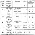 Spelling the suffixes of different parts of speech
 Higher professional education
 Rebus in Russian