Device of a soldering station with a hairdryer. Mastery Thermal Soldering Station with a hairdryer with their own hands. What it is
I have long wanted to make a soldering hair dryer. Ready I'm not interested. Since it took up the alteration of the BP ATH to the laboratory, it became possible to get 24-25 volts at currents to the amps 8. Really, my hair dryer works up to 5 amps. As a compressor, a hybrid from the axial fan was applied to the housing (snail) on the principles of the centrifugal fan. There were just centrifugal, but I am curious to try this option. Fragon turned out to be quite workable. It is no worse than other my centrifugal, even if there are aerodynamic resistances (the main problem of axial fans). I recommend that if you do not find a suitable turbine.
Obtained parameters
- The power of the heater is 110 watts.
- The supply voltage is adjustable in 24.2 volts.
- Current consumption up to 4.8 amps.
Mosfets from the boards with the lead-free solder takes quite. Small things all the more. The composite video output connector from the same fee also took. The video processor is no longer.
You can remove the smallers from the boards with a regular solder when 75 watts of power are quite comfortable. It is possible below to reduce the fan speed. At full capacity is completely removed by the forty-eyed chips. Boards from phones are easy.
Where to begin?
Decide with the power you can and want to get. Less than 100 watts meaning not so much. For trivia, it is enough, however, if the rest do it right. I went out at 100-110 watts. Rebib the video processors are not enough.
Second. The current you can get from the power source. It depends on the choice of nichrome for spirals. I have a nichrome of 0.4 mm. If sclerosis does not change, sold on the market as a spiral for a tile for 1.5 kW. I counted it optimal. A thin wire does not hold a form, thick requires a large current to obtain sufficient temperatures. For wire 0.4 mm, we need a current of about 3.5 - 5.5 amps. So that the wire fuses to a yellow glow is approximately. With intense blowing, its temperature will decrease. We remember that the wire diameter uniquely determines the current. But the power will have to gain voltage. Since my BP for this purpose gives out 24 volts in the district, on that and stopped. The resistance of the cold spiral in the district of 3 ohms turned out. In the preheated form by calculations - about 4. Spirals do not care what current, permanent or variable. You can power it directly from the transformer through the dimmer for adjustment. True trance will then buzz. And it should have enough power and winding, made quite thick wire to keep the selected current.
An important element is a fan. The axial can be used in the extreme case, but they do not care with the pushing of air in the labyrinths. Their lame - blow in a straight line. Therefore, a centrifugal fan is preferred for a hair dryer. It is just intended for pushing air through significant aerodynamic resistance. It so happened that some time ago was familiar, he demonstrated to me a system of heating his development. Where there is a centrifugal fan. Homemade too. It turned out that he made both possible errors for fans of this kind. Incorrectly chose the direction of rotation for the impeller from the vacuum cleaner and incorrectly performed a snail for it. I am not at all the fans at all, but I taught physics at school, the idea how it works. Well, like the topic has long been beaten, preparing the article I climbed into Google. And, to his surprise, he found that a little bit of a third of the pictures on this topic contains one of two or both mistakes immediately. Therefore, I will give my schemes so that no one is confused. Moreover, it has a direct meaning for beginners.
This is the general principle of building centrifugal fans. Three different options for possible impellers are shown. Options are actually more, but we are enough. I draw your attention is three different impellers. Just show partially. This is no case alone. As can be understood from the scheme, the impeller must "sweep" the air to the sides, thereby creating pressure. (Oh, these "Kostrilers" from Google draw something that they do not understand).
Red option at number 1 - the best. Green (2) worse. Blue (3) worse than the previous two, but it will work. If the direction of rotation of the impeller you have another, simply calmkalte the scheme.
I did almost the same thing, just put the impeller from the axial fan.

The impeller naturally works on the "blowing" of the air inside. The difference from the simple axial fan is that the energy on the twisting of the air flow is not lost in vain, but is used according to the principles of the centrifugal. In theory, such things need to patent.
The obtained hybrid works quite adequately. Noisy, but this is already lucky. The fact is that with a small diameter of the impeller (which is axial, that centrifugal) to ensure a sufficient air flow will have to give high engine speeds. With all the ensuing consequences. With a large impeller might be hiding, but the convenience of the hair dryer would be lower.
If you create a turbine, as I suggested, when choosing a base for a fan, preference should be given to small, with high speed, preferably straight blades (with saberoids will work worse). Blades the bigger the better. The coolest of their tilt (an angle of attack) the better. I used the impeller from a very old video card. 12 volts, about 1.5 watts. The diameter of the impeller is 37 mm. Use what you will find. Experiment.
Suitable centrifugal fans in almost finished form, or as the donors of the impeller with the engine for my snail. You can not put as I have "plastics", but perpendicular to the pheno. In the first attempts, I did it. And a very worthy showed a turbine from a laptop. And quieter too. But it is already very worn yes and is designed for 3.5 volts and I went to another.

My hybrid compressor is larger.

The main body of the snail made of polystyrene foam. It does not matter from what, at least from the tree. A fairly clearly visible structure. By the way, if you plan to make protection for the impeller, I extremely do not recommend the drilling of small holes in the upper lid. Want to know why - google the device of mechanical hand siren times of war. Noise will be higher than the one shown in three times.
As a sleeve for a hair dryer, a housing from battery 18650 was used. Mining technology to the type shown in this video (from a foreign Yutub-channel):
Only I did not bother with drilling, as the author offers, in the bush. Drilled a small drill. Drilled by 4 mm. Nadfil corrected if the center of the hole was shifted. A stepped drill drilled further, correcting the downtile at each step, if necessary. I also made the sleeve either. From some chandelier, a threaded tube with two thin nuts. One nut on the end slawed to no longer rotate, the second I clamp. Insert a fixed nut from the inside of the cup from the battery. Excess part of the thread drove for beauty. You can do without a sleeve, but the flow will be worse. Not a jet, but a consistent torch. Strongly thin not advise. Millimeters 7-10 inner diameter, as I think it will be more convenient. And the resistance of the air is unnecessary to create nothing.
Inside the cup from 18650 was laid with mica. The spiral was wound on a styling plate 14 mm wide. Nichrome diameter 0.4 mm. I wrapped 16 turns. You will focus on another supply voltage, the number of turns will have to pick up. The ends bent under 90 degrees. Leave the ends authentic, then doit the place. And this helix should be put on a ceramic tube. I bought at the Mitita Radiorenka at one time. Diameter 4 mm. In principle, almost anyone is suitable, only if the diameter is very different, it is possible to experiment with the width of the plate for winding. One end of the helix is \u200b\u200bpassed through a ceramic tube. The spiral, bowed to the ceramic tube, you need to "twist", shifting each next round relative to the previous one. We can unwind these 16 turns for a couple of revolutions - not bad. Since the length of the helix is \u200b\u200bsmall, it is necessary to strive to arrange it evenly. To enhance the heating of the air, I further inserted an impeller from galvanized iron (it is possible to tin), which additionally twists the air flow against spiral rotation, improving heat exchange. And at the same time, it serves for some centers of the ceramic tube inside the glass. The resulting spiral should be freely inserted inside the cup with a mica. But it is desirable that she does not blunt there. I'm inserted tight enough.

The picture shows that the most impeller to twist the air flow and can be seen as I braked the nichrome. Bened twice, twisted a bit, dressed and flattened the brass tubes from the tips of the NSHA 0.7-8 (you can tube from antenna, for example). The ends wrapped with a thin copper wire, drowned, silicone wires soldered from some heater (in principle, it is possible to use ordinary), and also called the brass tubes of soldering. All this is necessary to reduce the heating of the nichrome in the contact zone with the wire. On top of a fiberglass tube. Can be found in dead energy saving, for example. You can not solder, but use mechanical clamps. What will find. Keep in mind the spiral and impeller for twisting air should be isolated to eliminate closures on the body and among themselves.
The further "body" was collected from the pipe (applied in furniture and design affairs) and the hull from the car cigarette lighter (it dresses well on the cup from the battery), the benefit of them had a somewhat accumulated after experiments with an infrared soldering iron. Use what you will find is not fundamentally. The tube with the cigarette lighter body connected soldering. There is no special heating, it will endure. The ends of the hull cut the closer to get the semblance of the collet, for the clamp of the glass from 18650 through the piece of glass strokes, or just fiberglass for thermal insulation.
The shell of the air duct made from the fuster and soldered. The plate is soldered on top (I used foil fibercstolite) to which the fan screws. Threads for fastening screws cut right in it.

The spiral spinned not yet completely.

In the final form about it. This picture is more or less visible, as the rest of the wire decorated. This is not the final option, even without impeller.

At the exit.


A little about nutrition
Fan isted from duty. She is treching there. Put an increase in the Chinese converter by 12 volts configured. The fan turns on along with the Fan BP. A heating is turned on with the PS-ON key (the right upper corner of the BP). And first turn off the heating with this key after work, and after cooling the hair dryer, turn off the power (rear). The toggle switch is designed to switch the fan speed. Not yet implemented, there was no need to overheat the air flow. I plan to simply power the fan through a diode or two (you need to try), and the toggleer simply let the head of the diodes, closing them. The lower the flow rate, the stronger the air will be heated.
A little about the connector
I used Som Pope Mom. Where it from the boards. I swart like this: the heating two groups of three contacts (for 5 amps more than enough), on the fan one by one. Then the thermoclaim fixed-isolated.
Thus, the BP is stabilized (if not at the maximum of theft works), the fan power is stabilized, therefore the air temperature is stabilized.
Constructive satisfied. For amateur purposes, quite enough. With maximum heating, the metal pipe in the area of \u200b\u200bthe handle heats up quite significantly, but the hand completely tolerates. With normal operation, the pipe is simply warm. Those. Nothing will float there. The air flow through the tube completely copes with cooling. And the air duct is preferably located like me, closer to the handle. So that there is no reverse air flow from the hot zone. Feng has passed testing by disconnection after maximum heating. He was just de-energized. Together with the fan. Nothing paid.
For beginners: start the designs of this kind, it is necessary to get into the crust, honeycombs, etc. and contemplation of previously accumulated wealth. And with a large share of the likelihood, the fact that can be easy enough to use. This is me to the fact that the design does not have to completely repeat my.
In this video, you can see the whole course of making a self-made device, which is very useful to the home master. Soldering hair dryer is made according to the sketch presented.
How to disassemble the battery.
The most difficult hub of the hair dryer is the housing of the heating element. It is made of 3 parts - glasses, tubes and washers. A glass of stainless steel is taken from lithium-ion. It is very important here to note some rules for dismantling the battery. Be sure to discharge it before, by giving a load in the form of a powerful resistor, resistance of 5-10 ohms.
So proceed to the disassembly. First, from a glass, we remove the cover, for this you can take a metal hacksaw, squeezed in vice. We cut a glass where there is a deepening in the cylinder. After the lid is removed, the edge of the glass must be carefully fired to make it easier to remove the contents. Disassembly of the battery is preferably made outside the residential premises, as its composition is toxic. To keep the battery well in your hand, wrap it with several layers of skin, vinyl or similar by the properties of the material.
During the drilling of plates and electrolyte, it can scroll in a protective sheath. However, it is possible to save it to the final build assembly, since this film protects the glass from excess loads that can cause deformation. For drilling the end of the glass, the washers selected under the inner diameter of the glass are applicable. One of them will be a detail of the heater housing. In order to fix the washer to fix the hole when reinforcing the hole, you can use one idea. Cutting a glass can be performed in two approaches. First of all, drill a hole with a smaller drill, and then large. To create a hole with a cup of glass, you need to use the washers again, which will play the role of the template. When drilling thin-walled parts, we needed with sharpening cybing.
Some subtleties.
The extreme detail of this node is made from the telescopic antenna section. To do this, a device with a hacksaw was used in a viska. However, this method is useful for protecting thin-walled parts, but the hands are needed especially to take care! It is necessary to observe extreme caution.
To secure the pipe in a glass, one of its edges must be ruined. It is easy to do so, as telescopic antennas make plastic brass. To fasten the parts of this node, it is better to use screws, but you can replace them with copper ropters.
If we use separate power supplies for the heater and fan, only three electrical terminal blocks are enough to place on the board. Otherwise, 10 radio elements and a radiator cooling the transistor will be installed on the board. The scheme and drawings of all parts are in the accompanying article. We wash the heater spiral on the mandrel with an emphasis, if we do not want to measure the estimated length of the nichrome wire with a tape measure.

In order to prevent the arc discharge in the heater, we use a ceramic insulator. It can be removed from the delay line from the old TV. As you can see, disassemble the delay line is easy. Cut the ceramic tube is the easiest possible abrasive circle, corundum or diamond. To prevent the closure of the turns of the heater with the housing, we place a piece of mica or a mikanite, twisted into the tube. So much from the conclusions of each spiral in a ceramic insulator. To prevent interstetic closures, we stretch the spirals to a pre-applied tag. Measure the desired length of the conclusions of the heater spirals and wind them with a tinted copper wire in order to fully clamp the ends of the spirals in the electroclayers.
The thermal screen, like the other parts, we make the drawing-pattern. Patterns and detailed information on the calculation of the hair dryer can be found by clicking on the link that is now visible at the top of the screen.
As a hull, we use a polyethylene terephthalate bottle of water. By making two cuts, we turn the neck of the bottle into a four-point collet clamp. Fiberglass is insulating the heater body from the heat screen. Draw the cylindrical shape to the plates of the heat screen. Insert the heater housing together with the plates in the neck of the bottle and fix the lid, in which the hole is pre-cutting. Installing the nodes of the hair dryer inside the bottle housing is somewhat difficult, so it is better to choose a transparent bottle.
It is also worth paying attention to the fact that when using the bottle of another form, you will have to adjust the dimensions of the brackets and threaded sleeves, which the power board is attached to the walls of the bottle. The same applies to the clamp fastening the fan. Its length directly depends on the perimeter of the fan used.
Field tests of the homemade hair dryer.
Hairdryer is assembled. Let's start his test. Let's see what the limit features of the hair dryer. As you notice, with a decrease in air flow rate, it is possible to obtain a jet temperature of more than 600 degrees. This is also talking about tanned paper. The uniformity of heating and the shape of the jet of the air is looking through paper darkening. Solder melting speed is also a good fane power indicator. Thanks to 300-watt power, this hairdryer makes it possible to dismantle larger items than its stove fellow. Thank you for your attention and creative success!
Description of the device and drawings of the hair dryer - oldoffober.com/ru/heat_gan_2/
I have long wanted to buy a station, but because of financial problems I did not have the opportunity and I decided to have ever thought - whether it is impossible to make it with your own hands?
A little rummaged in the network and found such a https://www.youtube.com/watch?v\u003dWZGBTWLYZXO. The station is just what I need is to control the microcontroller, the output of the data on the LCD display 16x2, which displays.

The top line is the specified soldering room temperature and the active temperature on it, the data is updated several times per second (0-480gr)
The lower line is the preceded temperature of the hair dryer, the active temperature on it (0-480gr), as well as the rotational speed of the fan built into the hairdryer (0-99)


Board and scheme
You can download a printed circuit board (+ scheme and firmware), everything is in the original as the author.
Several tips for those who are too lazy to watch videos (although in them I explained quite in detail)
The size of the printed circuit board is already installed, the mirror is also not needed. Terminals, through which the controls are joined with the board, it is advisable to replace, i.e., instead of terminals, use the usual way to take the wires and secure into the appropriate holes on the board.
During etching, it is necessary to verify the sections of the board with the template, since in some places the findings of the SMD components may form a KZ, in the photo all this is perfectly visible

ATMEGA328 type MK is the same microcontroller, which is on the handballs of the programmer with the ARDUINO UNO set, in China there is a penny, but with MK you will need either a home-made programmer or a native Arduino Uno, as well as a quartz resonator to 16 MHz.

The MK is fully responsible for managing and outputting data on the LCD display. The station control is quite simple - 3 variable resistors on the 10kom (the most common, mono - 0.25 or 0.5 watts) first is responsible for the temperature of the soldering iron, the second - vein, the third increases or reduces the turnover of the cooler built into the hair dryer.


The soldering iron is controlled by a powerful field transistor, through which the current in up to 2 amp will occur, therefore it will be heating, it will also be heated and the simistor will be heated together with a transistor and a 12 volt stabilizer brought to the overall heat sink, additionally insulated the housing of these components from the radiator.


LEDs necessarily take 3mm with low consumption (20mA) due to the use of more powerful LEDs 5mm (70mA) I did not work a hairdryer, more precisely did not go heating. The reason is that the LED on the board and the LED, which is embedded in the tunnel (it actually controls the entire heating node of the hair dryer) is connected in series and simply lacked the power supply to the LED in the tluorized pulp.


Soldering iron
He himself took the Ya Xun soldering iron for stations of this type of 40 watts with durable sting. The plug has 5 pins (contact holes), pinout plug below

Take into account that in the photo the pinout plug, which is on the soldering iron itself,
The soldering iron has a built-in thermocouple, the data from which is accepted and decrypted by the station itself. Be sure to need a soldering iron with a thermocouple, and not with a thermistor as a temperature sensor.


The thermocouple has polarity, with an incorrect connection of the thermocouple, a soldering iron after turning on will type the maximum temperature and will become uncontrollable.

In principle, power can be from 350 to 700 watts, I advise no more than 400 watts,
that full enough for any needs. Hair dryer is also with a built-in thermocouple as a temperature sensor. The hairdryer should be with a built-in cooler. It has a nest of 8 pin, the slot pinion on the sole is presented below.


Inside the hair dryer, there is a 220 volt heater, thermocouple, fan and germ, the latter can immediately throw out, in this project it is not needed.
The heater does not have polarity, and the thermocouple and cooler - have, so that observe the polarity of the connection, otherwise the motor will not spin, and the heater drops the maximum temperature and becomes unmanageable.
Power Supply
Anyone (preferably stabilized adapter) 24 volts at least 2 amps, advice-4-5 amps. The universal chargers for laptops are perfectly suitable, in which there is the possibility of adjusting the output voltage of 12 to 24 volts, protection against short circuits and stabilized output - and it is worth a penny, he chose it itself.

You can also use a low-power supply unit for LED tapes 24 volts, there is a current from 1 amp.

You can also slightly finalize the electronic transformer (as the most fiscal option) and implement in the scheme, in more detail about the power blocks I explained at the end of the video (part 1)
You can also use a transformer power supply - can not be stabilized, but I repeat - stabilization is desirable.
Installation and housing
The housing from the Chinese radio tape recorder, the 16x2 displacer perfectly approached it, all controls are installed on a separate plastic sheet and are suitable for the bottom of the radio.


The main power components are strengthened on the heat sink, through additional insulating gaskets and plastic washers. The heat sink is taken from the non-working uninterrupted man.


It heats up, but only after a long work with a hairdryer at high power, but all this is tolerant, by the way - on the board there is an additional output of 12 volts for connecting the cooper, so that it is possible to blow the radiator if there is a need.


Setting
In principle, it is necessary to configure either a thermometer or a tester with a thermocouple and the possibility of measuring temperature.


To begin, it is necessary to put some temperature on the soldering iron (for example, 400gr) further press the thermocouple to the shatter's stall to understand the real temperature on the stare, well, and then it is easy to use a trimming resistor on the board (slow rotation) to compare the real temperature on the soldering iron (which is displayed on the display) with the one that shows the thermometer.
Everyone who tried to engage in the repair of electronics came to the realization that the soldering iron would be little. Some SMD items are simply impossible to fall without the help of a thermal dryer. That is why over time the soldering station is purchased, which includes both. Most cheap options rarely correspond to individual preferences. Therefore, the thermo-friendly soldering station does not have something unattainable. The article will consider various options for soldering stations, as well as the process of self-assembly.
What is a soldering station
If we say simply, the simple soldering station consists of several main blocks:
- power Supply;
- control block;
- indicators;
- manipulators.

The power supply can be pulsed or transformer. The first has smaller dimensions and is able to produce greater power. The transformer power supply has a characteristic sound when working and for high power requires large dimensions. In some cases, the transformer unit shows itself more reliable, but it directly affects the weight and dimensions of the solder station. The soldering station control unit consists of a board on which microcontrollers are located, variable resistors and other elements that are responsible for feedback, as well as for generating an output signal for manipulators.
As manipulators on a soldering station can be used:
- soldering iron;
- infrared head.
On the front panel of the station there are indicators. They display the readings of temperature sensors that are in manipulators. In most cases, additional calibration is required to achieve correct readings.
Varieties of stations

All soldering stations can be divided into two large groups:
- thermo-high;
- infrared.
Each of them is sharpened to their tasks. In most cases, during professional repairs, both varieties of soldering stations are required. The first is a small block that has one or two manipulators. The thermo-air soldering station may include only a hairdryer or hairdryer with a soldering iron. There are soldering stations that have only soldering iron as a manipulator. These are usually those species that are called induction. In conventional thermal stations, the heating of the soldering iron occurs due to the ceramic or similar element to which the voltage is supplied. This element transmits the temperature on the sting. In induction soldering stations, heating occurs due to the action of the electromagnetic field. Energy is immediately transmitted to the sting.

Thanks to this approach, it was possible to reduce the inertness of the soldering station, to increase the response time, as well as increase the power at smaller dimensions. In those products where heat-insulated elements are impossible to do without an induction station, since it is capable of heating large areas of tin in a short time. In some cases, even the thermo-friendly hairdryer is difficult to achieve. Induction is several times more expensive than ordinary stations, but their effectiveness guarantees pleasure and high accuracy when working.
Infrared soldering stations are a separate unit. In appearance, they practically unlike two previous views. They consist of two main modules:
- head or upper heating;
- lower heating.

The heating in them occurs due to infrared elements. Thanks to the lower heating, the board heats up evenly, which avoids deformation when removing or sealing certain elements. Most often infrared stations are used to replace chips with BGA soldering. They are chip-crystals that are fixed on the board with the help of special solder balls. Some types of such chips are possible to replace the usual thermal station, but the quality will suffer. The cost of a good infrared station begins from one thousand dollars.
Note! There is a separate subspecies of infrared stations in which the infrared element is placed in a manipulator that resembles a hairdryer. Such products have not been widespread and rarely applied.
Independent assembly
Two of the listed types of stations for soldering can be assembled independently. In most cases, ready-made modules that are on sale are used. If desired, you can develop your own scheme and assemble it, but often there is no need for it, since it is cheaper to buy ready-made components.
Term-friendly

The simplest thermal-wide soldering station can be collected from ordinary soldering iron. Below will be instructions in photos, as can be done. For the entire assembly process, components will be required:
- soldering iron with a wooden handle;
- aquarium compressor;
- screwdriver;
- drill;
- medical dropper;
- foil;
- part of the antenna;
- strategic wire.
The process begins with the fact that you need to disassemble the soldering iron. Screw is unscrewed and the sting is released.

The next step is removed the handle that will be needed later. Wires that connect the feed cable with the heating element are unscrewed.

The wire is pulled out of the handle and a small hole is drilled on the side.

Through the hole, the power wire is inserted. To make it easier to do, you can bind it to a piece of wire and pull it out.
Now the dropper harvested earlier. The part on which the gum is located, it is necessary to cut in half, as shown in the photo.

After that, the remaining part with the tube is inserted into the handle, where the power wire used to arrive.

The compound is pretty reliable and sealed. Next to the power supply, which has been traded into the drilled hole, the heating element is connected, seized earlier.

The wire is important to isolate well to not get a shock. The heating element is installed in its place. After that, the foil is wrapped in the heating element, which are designed for cooling, as shown in the photo.

To keep the foil in its place, it must be fixed with a copper wire, wrapped around the foil.

Nozzle, which will provide directional air flow, is made from a piece of the tubule from the antenna. It is just inserted into the place of the sting, as shown in the photo below.

The hole through which the power wire passes is good to seal. The usual sealant is suitable for these purposes. Next, aquarium compressor is connected to the second part of the tube from the dropper.


This result will be enough to work with small components on the boards. The power of such a hair dryer can be enhanced if you make a winding of a nichrome thread on the heating element, as well as put a compressor with greater performance. In a pair with a hairdryer, you can use a regular soldering iron. Such products can always be taken with you.

The process of assembling the product with a more complex structure is described in the video below.
Infrared
The infrared station is also quite realized independently. For this purpose you will need:
- soldering iron;
- pC power supply;
- car cigarette lighter.
The power supply can be used old. It will take only one working line with a voltage of 12 volts. No particular power required. From the soldering iron only the wooden handle will need. It can be used from any other instrument or make yourself. First of all, it is necessary to disassemble the cigarette lighter to get to the heating element, which is inside. The photo shows how it looks.

The next task is to secure the handle from the cigarette lighter on the handle from the soldering iron. To do this, you can use glue. Next, you need to drill a hole in the knob from the cigarette lighter, so that the feed wires can be brought through the hole. When the wires are connected, you can assemble the cigarette lighter module with a ceramic spacer, as shown in the photo below.

Secure the entire design on the handle using an additional metal plate. When all the ready wires are connected to the 12 volt power supply unit. The finished version of the mini station is shown below in the photo.

The station is compact, so it is easy to transport and can be powered by any source that is capable of submitting 12 volts of DC. It can even be a battery, so the station turned out completely autonomous. If you collect a small block of lithium-ion batteries 18650 with a 12 volt converter and install the charging controller, then the price of such a station will not be.

The heating of the mini station occurs almost instantly, and the maximum temperature may exceed 400 degrees. Small elements, such as capacitors and transistors, are aimed in supply, as seen in the photo below.

The platform to the soldering should be at least 10 mm. In addition to miniature SMD elements, the station can easily copes with chips in SOEC cases. The photo below shows the direct proof of that.

Also without much difficulties you can fall out and larger components. The station can be modified a little to get a convenient option for work. One of the modules that is easy to use is additionally a dimmer, as can be seen in the photo below.

Its purpose is the ability to adjust the power of the soldering station. As a power source, you can use no power supply from a PC, and the power supply for the LED tape, as can be seen in the photo below. It is easy to purchase at any store of electrical goods. The total power of the station is approximately 50 W, the strength of the current that will be required for its operation reaches 6 amps. It should be considered when choosing a power supply.

The disadvantage of such a soldering area can be considered the lack of contact with the element that is subjected to soldering. Because of this, there is no possibility to remove the surplus of the solder, and it is also impossible to correct the part, if it was skedyed with the displacement, and the solder has not yet cooled. It is advisable to provide a separate switching button on the handle, which will prevent the cigarette lighter overheating. While working such a station, it is necessary to keep the manipulator at an angle of 90 degrees to the element that rolls. This will make it possible to affect it with the entire heater area evenly.

Additionally, for a successful soldering of small elements, you will need a set of tweezers. Their sponges must be sharp in order to make it easier to capture miniature components. Also, do not do without a device called the "third hand". There are many of its variations, but the main purpose is the same everywhere. It consists in holding the supplied wires or ash microcircuits. To make it easier to consider small components, you need a good magnifying glass or microscope. An integral part of the Master's toolkit is good lighting. It is desirable if it is based on LEDs that do not have flicker when working. During soldering using the station, do not do without flux. This is a special solution that improves adhesion and cleans the metal for soldering. The variant of the infrared soldering station with the lower heating can also be collected independently. There is a video below.
Summary
As you can see, assemble your own soldering station is not as difficult as it may seem. At the same time, the costs of such a soldering station will be minimal, and it can be used everywhere. If we are talking about the professional level of repair work, then it makes sense to think about acquiring a high-quality factory soldering area, which has different modes of operation and settings. In training there is no point in buying an expensive soldering station, you can start with cheap soldering stations. If training will be successful and during this time will not be lost a desire for work, then you can think about the acquisition of a professional soldering station.
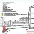 What is a hot water supply of an apartment building
 Water supply of an apartment building
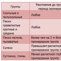 Calculation of the Load for the foundation Installed Electrical Instruments