Features of choosing, installing and operating automation of jilex. Automatics unit for pumps How the Djilex automation unit works
The automation mechanisms for the pump are used when equipping the autonomous operation of devices with the setting of the appropriate mode. In addition, high-quality automation ensures protection of pumps from dry stroke and saves electricity consumption. This approach allows you to extend the life of expensive pumping equipment.
A feature of automation from the company Djleks is the ability to use devices, both with branded models and with devices of other manufacturers. In addition, inexpensive equipment is characterized by a number of other beneficial properties.
1 Features of the Control Block
The main element of automating the process of pumping the company is the automation unit of the jilex. Such a device is connected directly to the pumping machine and reacts to the pressure level in the system.
It consists of a jilex block from a plastic housing with a metal lid. Inside the housing is a spring, an electronic unit, a complied with a pressure relay and a movable mechanism, flushing contacts when the pressure is reduced. For external control of the operation of the device in the side surface of the unit, a pressure gauge is mounted.
The device is designed to work on the basis of a pumping station or another surface pump pumping clean water. Use with a minor content of abrasive impurities is also possible, but in this case the device is completed with an additional filter.
1.1 Principle of action of the device
Djilex automation functions autonomously from the usual electrical network. After 30 seconds after installing and connecting the unit, it turns on and runs within a few seconds. Next, the device is turned off and activated only if the pressure in the line is changed.
When the valve at the water consumption point opens, the pipe pressure begins to quickly decline. In this case, the unit immediately turns on and when the minimum pressure indicator is reached, the electric pump activates. The device pumps water while the pressure is not aligned again (when the crane is closed). After the crane overlaps, the device works for another 5-20 seconds, continuing to pump water into the line. Such a measure is precaution, in case the pressure in the system falls below the norm and the device is not able to track the pressure level.
1.2 How is the Jelex automation unit (Djilex)? (VIDEO)
2 Correct installation of the device
Dzhelex 9001 automatics is installed in the supply line included with additional equipment. Therefore, the important stage is the correct installation and configuration of all components. Installing the automation unit The presstructrol from the jilex is carried out in the following order:
- First of all, if modification without measuring instruments is purchased, you should purchase a pressure gauge and install it on the sidebar. The mechanism is necessary to control and manag control.
- The automatic apparatus itself is crashed into the pipeline of the water supply on the site between the water consumption point (tap) and the pumping device. A block is installed exclusively in a vertical position, a blue metal cover up. In this case, the inlet of the device (indicated in the instruction) must be located on the pump release. The output hole carries further into the supply line.
- After the control apparatus is mounted in the line, it is necessary to thoroughly inspect all the joints and compounds for tightness. If the errors are found during installation, they should be sealing with sealant or connecting elements.
- Connecting the block to the network is carried out strictly according to the scheme specified in the manual. In this case, if the device completes the pump with a current of more than 10 amps, the magnetic starter is additionally installed. The main requirement to the electrical cable used with the device is increased resistance to high temperatures.

If necessary, the supply line is complemented by filters for water purification and the receiver to align the pressure in the system.
After all the components are mounted in the highway, you need to check the device. For this, the pump inlet on the pipeline is filled with liquid and the pump is turned on. One of the indicators lights up on the unit. This suggests that there is a contact between the block and the pumping machine. For several tens of seconds, the device works and turns off.
After the device is turned off, you must open one of the cranes (if there is a multi-level, then preferably the uppermost). At the same time there are two options:
- In the first case, water will go from the crane with a continuous, uninterrupted flow. The block turns on, and the pumping device works throughout the entire period of use of the crane. In this case, the installation of the device is made correctly.
- If the water flow is not stable or is absent at all, you can try to restart the device with the "Restart" button. The button is pressed and maintained until the pump device does not work. If, in this case, nothing has changed, a thorough inspection of the device and the whole line is carried out, and if necessary, dismantling and adjustment.
3 Compatible Pump Supports
Djilex automation is a versatile device. With it, the operation of pumping devices from various manufacturers can be adjusted. Regarding the principle of operation, such a pressure leveling mechanism is installed on a vibration, centrifugal, vortex, auger pump.
The most efficiently appliance is complete with pumping devices that meet the following characteristics:
- current power in the range of 6-10 A;
- device performance up to 100 l / min;
- voltage not higher than 250 V;
- the maximum temperature limit of the pumped liquid is 75 degrees;
- connecting to a pipe with a 1-inch cross section.
4 What other automotive options have Djilex?
In addition to the automation unit, the company produces less popular automation options for pumping equipment. One of these options is the installation of the crab jilex. The device is responsible for stable pressure in the supply lifting, it starts and turning off the pump if necessary. In addition, the filter element clears the stream from solid inclusions.
Djilex crab consists of such components:

- polymer hydrocratic;
- tank receiver with a volume of 24 or 50 l, coated with anti-corrosion enamel;
- electrical pressure relay;
- filter with a replaceable cartridge that is responsible for cleaning the water flow from impurities;
- pressure gauge;
- two electrical cables;
- special bracket for fixing the aggregate on the wall.
The device works on the basis of a standard electrical network by 220 V. Suitable for simultaneously connecting 2-3 points of water intake. The adjustable relay allows you to install before starting the pressure level, which will support the device. Like the previous type of devices, Crab 50 is a versatile device and is suitable for connecting any manufacturer on borehole pumps.
4.1 RDM-5 Pressure Relay
A simpler version of automation of the pumping station is to install a special RDM-5 relay on it. The compact device is mounted in the highway and is connected to the pumping unit using an electrical cable. The wire is fixed to the contacts of the relay.
The principle of the device is as follows. The device reacts to the pressure level in the line. If the indicator below the set value is connected, the current is fed to the water intake point and the liquid fills the pipeline until the pressure is normalized. When the pressure level comes to normal (this indicator is also exhibited by the user) - Contacts disagree. Current supply to the well unit is interrupted and it turns off.
The minimum and maximum indicators in which the pumping device is triggered by the user. You can carry out their settings using two nuts that fix the degree of voltage of the spring. A larger nut when rotating counterclockwise exhibits the maximum pressure indicator, the nut is smaller when rotating allows you to adjust the difference between the maximum and minimum indicator.
RDM-5 is designed for use exclusively in water. The operating voltage for the apparatus is 220-230 V. The temperature of the pumped liquid is 0-40 degrees. The relay is fixed to the pipeline with a cross section. Mandatory condition when using RDM-5 is high-quality grounding.
4.2 Float Switch
For drainage, fecal and surface pumps for water are the cheapest and practical way of automation is the float switch. In the field of use, such devices are divided into light and heavy. Light float are equipped with drainage models, heavy floats are installed at water supply stations and water pumps.

It consists of a construction of an electrical cable with a length of 3.5.8 or 10 m and a plastic float mechanism. Inside the float there are two contacts, switching lever and a ball changing the lever. In the number of wires, two and three-wire floats are highlighted.
In a variant with two wires, they are directly connected to the contacts of the float. When such a mechanism rises with water level to the designated level, the lever presses on the contacts, they climb and supply energy to the pump.
In models with three wires, it is maintained to include the point of the fence in the extreme top and in the extreme lower positions. To do this, one wire goes to one of the contacts, and two other wires depending on the position over the second contact.
The principle of operation of such a float mechanism is that the device automatically turns on the pump when the water level rises to the displayed indicator. In the case of a two-wire device, the float, on the contrary, opens the contacts and turns off the device when water falls below the norm.
The automation mechanisms for the pump are used when equipping the autonomous operation of devices with the setting of the appropriate mode. In addition, high-quality automation ensures protection of pumps from dry stroke and saves electricity consumption. This approach allows you to extend the life of expensive pumping equipment.
A feature of automation from the company Djleks is the ability to use devices, both with branded models and with devices of other manufacturers. In addition, inexpensive equipment is characterized by a number of other beneficial properties.
1 Features of the Company Control Block
The main element of automating the process of pumping the company is the automation unit of the jilex. Such a device is connected directly to the pumping machine and reacts to the pressure level in the system.
It consists of a jilex block from a plastic housing with a metal lid. Inside the housing is a spring, an electronic unit, a complied with a pressure relay and a movable mechanism, flushing contacts when the pressure is reduced. For external control of the operation of the device in the side surface of the unit, a pressure gauge is mounted.
The device is designed to work on the basis of a pumping station or another surface pump pumping clean water. Use with a minor content of abrasive impurities is also possible, but in this case the device is completed with an additional filter.
to the menu
1.1 Principle of action of the device
Djilex automation functions autonomously from the usual electrical network. After 30 seconds after installing and connecting the unit, it turns on and runs within a few seconds. Next, the device is turned off and activated only if the pressure in the line is changed.
When the valve at the water consumption point opens, the pipe pressure begins to quickly decline. In this case, the unit immediately turns on and when the minimum pressure indicator is reached, the electric pump activates. The device pumps water while the pressure is not aligned again (when the crane is closed). After the crane overlaps, the device works for another 5-20 seconds, continuing to pump water into the line. Such a measure is precaution, in case the pressure in the system falls below the norm and the device is not able to track the pressure level.
to the menu
1.2 Jelex Automation Block: We consider inside (video)
2 Correct installation of the device
Dzhelex 9001 automatics is installed in the supply line included with additional equipment. Therefore, the important stage is the correct installation and configuration of all components. Installing the automation unit The presstructrol from the jilex is carried out in the following order:
- First of all, if modification without measuring instruments is purchased, you should purchase a pressure gauge and install it on the sidebar. The mechanism is necessary to control and manag control.
- The automatic apparatus itself is crashed into the pipeline of the water supply on the site between the water consumption point (tap) and the pumping device. A block is installed exclusively in a vertical position, a blue metal cover up. In this case, the inlet of the device (indicated in the instruction) must be located on the pump release. The output hole carries further into the supply line.
- After the control apparatus is mounted in the line, it is necessary to thoroughly inspect all the joints and compounds for tightness. If the errors are found during installation, they should be sealing with sealant or connecting elements.
- Connecting the block to the network is carried out strictly according to the scheme specified in the manual. In this case, if the device completes the pump with a current of more than 10 amps, the magnetic starter is additionally installed. The main requirement to the electrical cable used with the device is increased resistance to high temperatures.
If necessary, the supply line is complemented by filters for water purification and the receiver to align the pressure in the system.
After all the components are mounted in the highway, you need to check the device. For this, the pump inlet on the pipeline is filled with liquid and the pump is turned on. One of the indicators lights up on the unit. This suggests that there is a contact between the block and the pumping machine. For several tens of seconds, the device works and turns off.
After the device is turned off, you must open one of the cranes (if there is a multi-level, then preferably the uppermost). At the same time there are two options:
- In the first case, water will go from the crane with a continuous, uninterrupted flow. The block turns on, and the pumping device works throughout the entire period of use of the crane. In this case, the installation of the device is made correctly.
- If the water flow is not stable or is absent at all, you can try to restart the device with the "Restart" button. The button is pressed and maintained until the pump device does not work. If, in this case, nothing has changed, a thorough inspection of the device and the whole line is carried out, and if necessary, dismantling and adjustment.
3 Compatible Pump Supports
Djilex automation is a versatile device. With it, the operation of pumping devices from various manufacturers can be adjusted. Regarding the principle of operation, such a pressure leveling mechanism is installed on a vibration, centrifugal, vortex, auger pump.
The most efficiently appliance is complete with pumping devices that meet the following characteristics:
- current power in the range of 6-10 A;
- device performance up to 100 l / min;
- voltage not higher than 250 V;
- the maximum temperature limit of the pumped liquid is 75 degrees;
- connecting to a pipe with a 1-inch cross section.
4 Other Variants of Jielex Automation
In addition to the automation unit, the company produces less popular automation options for pumping equipment. One of these options is the installation of the crab jilex. The device is responsible for stable pressure in the supply lifting, it starts and turning off the pump if necessary. In addition, the filter element clears the stream from solid inclusions.
Djilex crab consists of such components:
- polymer hydrocratic;
- tank receiver with a volume of 24 or 50 l, coated with anti-corrosion enamel;
- electrical pressure relay;
- filter with a replaceable cartridge that is responsible for cleaning the water flow from impurities;
- pressure gauge;
- two electrical cables;
- special bracket for fixing the aggregate on the wall.
The device works on the basis of a standard electrical network by 220 V. Suitable for simultaneously connecting 2-3 points of water intake. The adjustable relay allows you to install before starting the pressure level, which will support the device. Like the previous type of devices, Crab 50 is a versatile device and is suitable for connecting any manufacturer on borehole pumps.
to the menu
4.1 RDM-5 Pressure Relay
A simpler version of automation of the pumping station is to install a special RDM-5 relay on it. The compact device is mounted in the highway and is connected to the pumping unit using an electrical cable. The wire is fixed to the contacts of the relay.
The principle of the device is as follows. The device reacts to the pressure level in the line. If the indicator below the set value is connected, the current is fed to the water intake point and the liquid fills the pipeline until the pressure is normalized. When the pressure level comes to normal (this indicator is also exhibited by the user) - Contacts disagree. Current supply to the well unit is interrupted and it turns off.
The minimum and maximum indicators in which the pumping device is triggered by the user. You can carry out their settings using two nuts that fix the degree of voltage of the spring. A larger nut when rotating counterclockwise exhibits the maximum pressure indicator, the nut is smaller when rotating allows you to adjust the difference between the maximum and minimum indicator.
RDM-5 is designed for use exclusively in water. The operating voltage for the apparatus is 220-230 V. The temperature of the pumped liquid is 0-40 degrees. The relay is fixed to the pipeline with a cross section. Mandatory condition when using RDM-5 is high-quality grounding.
to the menu
4.2 Float Switch Jieks
For drainage, fecal and surface pumps for water are the cheapest and practical way of automation is the float switch. In the field of use, such devices are divided into light and heavy. Light float are equipped with drainage models, heavy floats are installed at water supply stations and water pumps.
It consists of a construction of an electrical cable with a length of 3.5.8 or 10 m and a plastic float mechanism. Inside the float there are two contacts, switching lever and a ball changing the lever. In the number of wires, two and three-wire floats are highlighted.
In a variant with two wires, they are directly connected to the contacts of the float. When such a mechanism rises with water level to the designated level, the lever presses on the contacts, they climb and supply energy to the pump.
In models with three wires, it is maintained to include the point of the fence in the extreme top and in the extreme lower positions. To do this, one wire goes to one of the contacts, and two other wires depending on the position over the second contact.
The principle of operation of such a float mechanism is that the device automatically turns on the pump when the water level rises to the displayed indicator. In the case of a two-wire device, the float, on the contrary, opens the contacts and turns off the device when water falls below the norm.
byreniepro.ru.
Device and principle of water pressure relay
Constructively, the relay is performed as a compact block with maximum and minimum pressure springs, the tension of which is controlled by nuts. The membrane associated with springs responds to a change in pressure force. When the minimum value of the spring weakens, with a maximum level, it is shrinking stronger. The impact on the spring causes opening (closure) of the relay contacts, turning off or including the pump.
The presence of a relay in the water supply system allows for continuous pressure in the system and the necessary water pressure. The pump is controlled automatically. Properly exhibited minimum and maximum pressure levels provide its periodic shutdown, which contributes to a significant increase in the time of the trouble-free service.
The sequence of the pump station running the relay is as follows:
- Pump pumps water into the tank.
- Water pressure is constantly increasing that you can track the pressure gauge.
- When the installed limit top pressure is reached, the relay is triggered and disables the pump.
- As the water is spent in the tank, pressure is reduced. When it reaches the lower level, the pump will again turn on and the cycle will repeat.
The main parameters of the relay work:
- Lower pressure (inclusion level). Relay contacts, including the pump, closes, and water enters the tank.
- Top pressure (shutdown level). Relay contacts open, the pump is turned off.
- The pressure range is the difference between the two previous indicators.
- The value of the maximum allowable shutdown pressure.
Back to content
Setting up pressure relay
In the process of assembling the pumping station, special attention is paid to the pressure relay setting. From how correctly its limit levels will be exhibited, the ease of operation of the water supply system, as well as the timing of the trouble-free service of all components of the device, depends.

At the first stage, it is necessary to check the pressure that was created in the tank in the manufacture of a pumping station. Usually, in the factory conditions, the level of inclusion in 1.5 atmosphere is set, and the shutdown is 2.5 atmosphere. Check this with an empty tank and disconnected from the power supply of the pumping station. It is recommended to check the automotive mechanical pressure gauge. It is placed in a metal case, so measurements are obtained more accurate than using electronic or plastic pressure gauges. Their testimony may affect both the air temperature and the charge level of the battery. It is desirable that the limit of the gauge scale is as small as possible. Because on the scale, for example, in 50 atmospheres it will very difficult to accurately measure one atmosphere.
To check the pressure in the tank, you need to unscrew the cap, closing the spool, connect the pressure gauge and remove the reading by its scale. Air pressure should continue to periodically check, for example, once a month. Water should be completely removed from the tank, turning off the pump and opening all the cranes.

Another option is possible - carefully monitor the pump disconnection. If it has increased, it will mean a decrease in air pressure in the tank. The smaller the air pressure is, the greater the supply of water can be created. However, the pressure variation from the fully filled to almost devastated tank is obtained large, and all this will depend on the consumer preferences.
By selecting the desired mode of operation, you need to install it by hiding excess air for that, or drop additional. It should be borne in mind that one should not reduce the pressure to a value of less than one atmosphere, as well as to join it. Because of the small amount of air, the rubber container filled with water inside the tank will touch its walls and sway. And the surplus will not give the opportunity to pump a lot of water, because a significant part of the tank volume will occupy air.
Back to content
Setting the pressure on and off pressure levels
In pumping stations that are supplied in the assembled form, the pressure switch is pre-configured by the optimal option. But when it is installed from various elements on site, the relay setting must be carried out. This is due to the need to ensure the effective relationship of the relay settings with the tank volume and pump pressure. In addition, it is necessary to change the initial pressure relay setting. The procedure should be as follows:

In practice, the power of pumps is chosen such that does not allow pumping the tank to the extreme limit. Usually, the disconnection pressure is set to a pair of atmospheres above the inclusion threshold.

The installation of limit pressure levels is allowed, which differ from the recommended values. In this way, you can specify your own version of the mode of operation of the pumping station. Moreover, when setting the pressure difference with a small nut, it is necessary to proceed from the fact that the bottom level is installed by a large nut. You can only set the top level within the limits of which the system is calculated. In addition, rubber hoses and other plumbers also withstand pressure, not higher than the estimated. All this must be considered when installing the pumping station. In addition, excessive water pressure from the crane is often completely unnecessary and uncomfortable.

Back to content
Adjusting the pressure relay
Adjusting the pressure relay is practiced in cases where it is necessary to set up the levels of the upper and lower pressures in the specified values. For example, you need to set up the upper pressure of 3 atmospheres, the lower is 1.7 atmosphere. The process of adjustment is as follows:
- Turn on the pump and pump water to the tank to the pressure value on the pressure gauge 3 atmosphere.
- Disable pump.
- Open the relay cover and slowly rotate a small nut until the relay works. The rotation of the nut clockwise means an increase in pressure in the opposite direction - a decrease. The upper level is set - 3 atmosphere.
- Open a tap and drain the water from the tank to the pressure value on the pressure gauge 1.7 atmosphere.
- Close the tap.
- Open the relay lid and slowly rotate a large nut before the contacts are triggered. The lower level is set - 1.7 atmosphere. It must be somewhat larger than air pressure in the tank.
If high pressure is specified for shutdown and low - for inclusion, the tank is filled with plenty of water, and there is no need to turn on the pump often. Disadvantages occur only because of the large pressure drop when the tank is complete or almost empty. In other cases, when the pressure range is small, and the pump often has to pump, water pressure in the system is uniform and sufficiently comfortable.
In the next article, you will learn about the connection of the hydroaccumulator to the water supply system - the most common connection schemes.
delai-remont.com.
How does the pressure switch on the hydroaccumulator work?
The hydroaccumulator is associated with the pressure switch and the pump is the most important parts of the water supply for cottages, farms and other buildings. A properly configured and installed sensor allows you to save the owner from most problems related to water.
Connecting the pressure relay and the installation of additional equipment is difficult, it requires attention and specific knowledge in electronics and the operation of the pumping station with a hydroaccumulator.
1 Description of the sensor and pumping system
The water pressure sensor is an electrical device that provides pressure adjustment in the hydroaccumulator for the pumping station. It also monitors the pressure of the liquid in the pipeline and includes, or turns off the water supply to the tank of the hydroaccumulator.
This is due to the closure of the wires. Excess the permissible threshold opens contacts and the relay disables the pump. The drop below the installed level closes the device's contact, including water supply. You can manually configure both the upper and lower thresholds.

Pressure relay operation scheme
Basic concepts of pressure relay for a system with a hydroaccumulator:
- RVLC - Nizhny pressure threshold, power on, in standard settings is 1.5 bar. Contacts are connected, and the pump connected to the relay begins to pump water;
- Pipple - the upper pressure threshold, power off the relay, it is better to install at 2.5-3 bar. The circuit is disconnected, and the automatic signal stops the operation of the pumps;
- delta P (et) - indicator of the pressure difference between the lower and the upper thresholds;
- maximum pressure - as a rule, does not exceed 5 bar. This value is displayed in the characteristics of the control device for water supply systems and does not change. Exceeding leads to equipment breakdown or reduced warranty operational period.
The main element of the pressure relay for the hydroaccumulator is the membrane reacting to water pressure. It is bent depending on the pressure and informs the mechanism on how much water pressure in the pumping station falls or lowers. Bending switches contacts inside the relay. Counteracts the Water Online Special Spring (which is delayed for adjustment). Spring smaller determines the differential, that is, the difference between the lower and the upper pressure threshold.
The relay can be two types. The first, power, directly acts on the contacts of the pump. The control type interacts with the automation of the station and already through it affects the operation of the pump.
The hydroaccumulator and pressure switch form a reliable system to ensure water supply of any premises, household buildings, fields and the other. Automation for the pump is also the necessary part - thanks to it, it becomes the most simply controlling the collection of water and quickly pump fluid into the tank and in the pipes.

Pressure Station Pressure Relay
You can always connect an additional hydroaccumulator, as well as relays, automation, sensors and pumps.
to the menu
1.1 Adjusting the pressure relay for the hydroaccumulator
Before connecting the equipment to Baku, the relay performance should be checked and adjusted it. Remove the testimony recommended by a mechanical pressure gauge. It more points and less susceptible to internal breakdowns, due to which its testimony may not be valid.
Next will follow the instruction, how to properly configure the pressure relay. First of all, it is necessary to familiarize yourself with the passport of the device, pump and tank of the hydroaccumulator to find out the pressure limits for these elements of the pumping station. More appropriate when buying in advance to get acquainted with these parameters And adjust them to each other.
- Open water consumption (faucet, hose, valve) so that thanks to the pressure gauge to see the pressure at which the relay is triggered and the pump turns on. Usually it is 1.5-1 bar.
- Water consumption is disabled to raise the pressure in the system (in the hydroaccumulator tank). The pressure gauge is fixed by the limit at which the relay disables the pump. This is usually 2.5-3 bars.
- Adjust the nut attached to the large spring. It defines the value at which the pump is turned on. To increase the inclusion threshold, you need to tighten the nut clockwise to reduce - weaken (counterclockwise). Repeat previous points until the inclusion pressure will not match the desired one.
- Adjusting the shutdown sensor occurs with a naile on a small spring. She is responsible for the difference between the two thresholds and the configuration principle is the same: to increase the difference (and increase the pressure of shutdown) - tighten the nut to reduce - weaken.
- It is not recommended to make a rotation of the nut more than 360 degrees, because they are very sensitive.
1.2 How to set up pressure switch on a pumping station? (video)
2 pump with hydroaccumulator
Since the sensor also determines the air pressure in the hydroaccumulator of the pumping station, a description of this equipment should be known. This will provide a competent connection of the hydroaccumulator. If seriously think about how to choose a hydroaccumulator, you should pay attention to the following positions.
The device is a metal tank at 19, 24, 50 liters and more, up to 1000. The tanks for 50 and 24 liters are the most common for country sites and small country houses. but it should be borne in mind that the total volume of the tank is not the volume of water.. which can contain it. Inside the tank of the hydroaccumulator, the air pressure must be approximately 0.2-0.3 the bar is less than in the pipeline.
It is necessary to choose to take into account the settings of the pressure of pressure, the higher the installation and more enduring device, the more you can load water into the tank. So in the pumping station with a tank of 24 liters, at a pressure of a pillette equal to 2.5, and the RVLC is equal to 1.0, the volume of stored water will be 9 with a small liter. Special tables will allow competently choose the volume of the tank and the power of the pressure relay. What better fit - depends on the depth of the well, the length of the pipeline and frequency and the objectives of use.
Pumping stations with a hydroaccumulator are pear and membrane. The first type has an internal rubber capacity, "pear," into which air is pumped into the pump. The pear is expanding and presses on the water inside the tank, providing its proceeds along the pipes. How to pump air into the "pear"?

Pump with hydroaccumulator
To do this, use a regular air pump and automotive nipple. In the membrane, a little differently arranged: water is injected into the rubber capacity (from butyl) water, the air presses with the outer side of the tank. Air is located between the metal walls of the tank and the water membrane.
The hydroaccumulator to the submersible pump is connected through the system consisting of the following elements:
- pressure switch;
- dry stroke sensor;
- pipeline chain;
- water purification filters;
- automation unit and optional equipment.
2.1 Pressure Checking Hydroaccumulator
Before connecting to the network and the pumping system, the hydroaccumulator must undergo pressure test. Since the principle of operation of the pumping station lies in the pressure of pressure in pipes using relays, pumps and a hydroaccumulator, then check is an extremely important operation. Tracking the pressure level of the air, which will overcome due to wear, breakdown, clogging, the most complex part of the prevention of the pumping station.
Indicators are removed by a manometer. It is necessary to remove the decorative cap and connect the pressure gauge to the nipple of the hydroaccumulator tank. An acceptable is usually considered a figure of 1.5 bar. However, it is less suitable - up to 0.8, depending on the type of tank. This adjusts the hydroaccumulator for the pumping station.

A set of tools for connecting the hydroaccumulator
Adjusting the air pressure inside the tank will change the water pressure. The pressure of the water above, the wear of the system is faster. Low water pressure will not allow the use of hydromassage shower or a jacuzzi, but will significantly save money on repair and replacing parts of the hydraulic pump system.
to the menu
2.2 How to connect the hydroaccumulator to the relay?
The relay is connected to the power supply with two pairs of contacts. The connection is connected to the pipeline with a threaded hole, the standard diameter of which is 0.25 inches (6 millimeters). In order to independently provide a pumping pressure switch, the following tools are required:
- the coupling with a cape nut (among the people "American"), as a rule, uses diameter 1 ";
- coupling with a collet clamp;
- mRN coupling;
- brass adapter;
- hermetic tape seal (desirable, FMU, it provides a stable pump connection to the hydroaccumulator);
- pipes, fittings, pressure switch, hydroaccumulator.

Connection diagram of hydroaccumulator to water supply
The diagram of connecting the hydroaccumulator to the pumping station with their own hands as follows:
- The hydroaccumulator tank thread is required to be sealing the ribbon to avoid water leaks, air penetration into the system, facilitating the prevention, as well as for a simpler subsequent repair and replace pipes.
- Relay pressure is connected not directly, but using a clutch with a cape nut. This is also done for simplicity of further repair of equipment and more dense insulation of the pipeline. This clutch also facilitates both connection and subsequent automation setting.
- The relay connects under the required angle to, when the equipment is installed, it was possible to easily monitor the indicators. It takes into account that sometimes all the automation put in hard-to-reach places - in narrow shorts, small technical rooms, even lowered inside the closed well or well. Therefore, it is very important to determine the required angle of inclination of the relay and it is possible to combine it with other works, and not directly with the tank.
- The pressure gauge, just in case, can also be placed with a hermetic ribbon, although the gasket is used there.
- From plastic pipe fittings, it is necessary to smear the knee for the consumer line.
- The regulator is connected to the knee due to the PRN clutch soldered to the pipe and with a brass adapter.
- For deep, submersible pumps, polyethylene pipes are used more often. To hermetically connected them to the relay, a clutch with a collet clip is required.
- The preparatory part is completed and then it is necessary to connect the hydroaccumulator and pressure switch with the rest of the pumping station.
- After connecting to the pipeline, you need to connect electricity.
- The mounting of the regulator cover is unscrewed by the usual scold. Inside there are introductory holes to which the power wires are summed up and pump cable. Contacts are signed, or they are indicated in the instructions.
This way is connected to the pressure relay and the hydroaccumulator to the pumping station.
Setting the pressure relay and adjusting the air pressure in the hydroaccumulator.
Pressure switch - an element that controls the operation of the pumping station (for example Aquajet or aquajet-inox) and which makes it possible to work in automatic mode. Pressure relay has several characteristics:
- Pressure pressure (P incl) - this is the pressure (bar), in which the pumping station is turned on by closing the contacts in the pressure relay. Sometimes the inclusion pressure is also called "lower" pressure.
- Turning off (P OFF) - This is the pressure (bar), in which the pumping station is turned off by opening the contacts in the pressure switch. Sometimes the shutdown pressure is also called "upper" pressure.
- Pressure drop (Δp.) - the absolute difference between the pressure of the shutdown and pressure pressure (bar).
- Maximum shutdown pressure - This is the maximum pressure (bar), in which it is possible to disable the pumping station.
Any pressure relay has factory settings and, as a rule, they are as follows:
Inclusion pressure: 1.5-1.8 bar
Shutdown pressure: 2.5-3 bar
Maximum shutdown pressure: 5 bar
How it all works:
Suppose the pumping station is connected (about this in the article "Preparation of the DAB pump station to work"), and the entire system is filled with water. After opening any crane (shower, washing, etc.) and the start of the waters, the pressure in the system will begin smoothly (thanks to the membrane hydrobacco) to fall, which is easy to track the pressure gauge. All this time, water enters the consumer from a hydraulic panel. When the "bottom" turning pressure is reached (it can also be traced on the pressure gauge at the moment of turning on the pump) the contacts inside the pressure relay will be closed and the pump will start. All the rest of the water treatment time the pump continues to work, feeding water directly to the consumer. After the completion of the water treatment (all cranes are closed), the pump still continues to work, only the water is not supplied to the consumer, but it hits the hydrobic (since it is nowhere to go) and the pressure smoothly increases. When the shutdown pressure is reached (you can easily track down the pressure gauge at the time of stopping the pump), the contacts inside the pressure relay are opened and the pump stops. With the next water treatment, the cycle is repeated. Everything is quite simple.
But what to do if the factory settings of the pressure relay are not very comfortable? For example:on the upper floors, the pressure drops very noticeably, or the water purification system requires at the entrance of at least 2.5 bar, while the pump is turned on only at 1.5-1.8 bar.
Customize the pressure relay can be independently:
We write on the pressure gauge pressure and turn off pressure when the pump is running. Turn off the power from the pump and remove the top cover of the pressure relay (as a rule, unscrewing one screw). You will see two screws, one bigger, is in the upper part of the relay, and the second, a little smaller size, is under it. The top screw is responsible for the pressure of shutdown and as a rule, next to it is the letter "P" and the arrow with "+" and "-" signs. Then rotate the screw in the desired direction (if the shutdown pressure must be raised, then rotate in the direction of the "+" sign, if you lower the sign "-"). How much to rotate? Make a turn (half of the turnover, one and a half - how much you want). After that, launch the pump and look at what pressure it turns off now. We remember, turn off the power of the pump, and rotate the screw further, start the pump again and write a new value, thus approaching the desired value.
The lower screw is responsible for the difference between the shutdown pressure and pressure pressure. As a rule, "Δp" is written next and there is an arrow with "+" and & laquo- "signs. Setting the pressure difference is similar to setting off the shutdown pressure. There is only one question as it should be? The difference between pressure and shutdown pressure is usually 1.0-1.5 bar. Moreover, the higher the pressure of the shutdown, the greater maybe this difference may be. For example, with factory settings P ON \u003d 1.6 bar, P off \u003d 2.6 bar difference is 1 bar, this is just a standard value. If we want to change the factory settings and raise p off to 4 bar, then the difference can be made in 1.5 bar, i.e. P ON must be installed at the level of 2.5 bar. It should be understood that the more this difference, the higher the pressure drop in the system, which is not always comfortable. But at the same time, the pump will be placed less often, and more water will come from the hydraulicock until the pump is turned on.
This is true only when the pump can provide the desired pressure (see the pump characteristic). Those. If the pump can only issue a passport for only 3.5 bar (including all types of losses), then the setting of the pressure relay for switching off 4 bar will not give anything. The pump simply will not be able to provide the required pressure and in this case will not stop. And if you still need 4 bar just, you will have to change the pump to more powerful.
How nevertheless should the air pressure in the air cavity should be?
Many people do not think, or simply do not know what you need to watch even behind it. Unfortunately, yes, you need, the service life of the membrane of the hydraulic panel directly depends on this, and ultimately, and the pump.
Measure the pressure of the air in the air cavity of the hydraulician. We do that only on the hydrobook disconnected from the system - Turn off the power of the pump, open any crane behind the pump and wait until the water come out of the hydraulic panel. Either measure the installation not yet connected to the water supply system. To do this, remove the decorative cap from the air nipple of the hydraulician and connect the usual car pressure gauge to it (to test the pressure in the car's tires). I remember this pressure. (As a rule, on small hydraulic packers, a capacity of up to 50 liters, this pressure will be 1.5 bar). Now the most important rule : Air pressure in the hydraulication should be less than the pressure of the pump is about 10%. Those. If the pressure on the pump is 1.6 bar, then the air pressure should be 1,4-1.5 bar. In most cases, this is the factory settings that were mentioned above. Those. Buying a finished pumping station, you already have a fully configured system. But as soon as you have made changes to the factory settings of the pressure relay, it is necessary to always change the air pressure in the hydraulic. For example, if you installed P on \u003d 2.5 bar, P off \u003d 3.5 bar, then the air pressure is necessary to raise up to a value of 2.2-2.3 bar.
By the way, even if you have not changed anything in the factory settings, you must regularly monitor, or, at least, control it once a year at the beginning of the summer season. It is important that this pressure is permanent, if it decreased a little over the winter, it can always be raised by the usual automotive pump to the required level.
All these simple operations will not take much time, it is enough to pay them attention once a year, especially since everyone will pay off the long and uninterrupted work of the entire water supply system as a whole.
2007 Dab-shop.ru Setting the pressure relay and adjusting the air pressure in the hydroaccumulator.
Pressure Relay for Hydroaccumulator: Installation and Setup Information
When providing a structure with water from a well or well, a hydroaccumulator is mandatory, which is a tank of a suitable volume. It is commonly used in conjunction with a special pressure switch. For a hydroaccumulator, it is a control device that reduces the number of pump cycles.

The main components of the pumping unit with a hydroaccumulator
Working elements fixtures and functioning
From the point of view of structural features, the relay is a block of small size equipped with special springs. The first of them determines the limit of the maximum pressure, and the second is minimal. The setting is performed using auxiliary nuts placed inside the housing.

Acquaintance with the internal structure of the device
Working springs are connected to a membrane that responds to pressure jumps by either otherwise. The exceeding maximum indicators leads to a compression of a metal spiral, and a decrease - to stretching. Thanks to such a device, a closure and opening of contacts at a certain point is carried out in the contact group.

The location of the device in the general scheme
The principle of operation of the pressure relay for the hydroaccumulator is as follows. Water comes into the membrane tank until its full filling, which leads to pressure growth. With the achievement of the maximum permissible level, the pump stops swing fluid.
As water flows, the pressure in the system falls. When overcoming the lower level, the equipment will turn on again. Turning and off cycles are repeated again and again until the elements of the system are in working condition.

Connection diagram in the presence of a drain crane in the system
Usually the relay consists of the following elements:
- plastic housings;
- rubber membrane;
- brass piston;
- membrane lid;
- threaded spills;
- metal plate;
- couplings for fixing the cable;
- pads for terminals;
- hinged platform;
- adjusting springs;
- contact node.

Using a pressure gauge, you can visually determine the pressure
Addition! When working on the movable part of the platform, adjustment springs, opposing the effort generated by the piston. The switching on and off the pump depends on the degree of their compression.
Optimal pressure inside the hydraulic tank
Any hydroaccumulator inside has a rubber membrane that shares the space into two cameras. One of these contains water, and in the other - compressed air. Due to such a structure, it is possible to create the desired pressure when filling and emptying the rubber container.

A hydraulic battery device is clearly shown.
To extend the service life of the device, you need to know how pressure should be in the hydroaccumulator. It depends largely on the indicators displayed to turn on the pump. The pressure inside the tank must be approximately 10 percent less.

Tank pressure check
For example, if the inclusion is installed on 2.5 bar, and the off is 3.5 bar, then the air pressure inside the tank is adjusted by 2.3 bar. Finished pumping stations usually do not require additional adjustment.
Connecting and configuring pressure switch for hydroaccumulator
Although many consider the installation process and adjusting the device difficult to understand, in fact he is not. Each owner of the country house with a well or well can independently connect and configure the device to ensure the structure of water.

One of the schemes for connecting the hydroaccumulator to the system
Standard Pressure Relay Connection Scheme for Hydroaccumulator
The finished product interacts both with plumbing and with an electrical system of the building. When the contacts are closed and opening, the liquid is supplied either. The pressure device is installed inpatient, as it is not necessary to move it from place to place.

The appointment of contact groups of the device is indicated.
To connect, it is recommended to highlight a separate line of electricity. Directly from the shield should hold a cable with a copper residential cross section of 2.5 kV. mm. It is not recommended to connect wires without grounding, because the combination of water and electricity is tatting a hidden danger.

Visual Scheme for Self Connection Relay
Cables should be skipped through the holes located on the plastic case, then connect to the contact block. It contains terminals for phase and zero, grounding. Wires for the pump.
Note! Electrical work should be carried out in a disconnected state from the network. When installing, it is impossible to neglect the overall technical safety regulations.
Proper tuning pressure switch hydroaccumulator
To adjust the instrument, an accurate pressure gauge is required, which allows you to determine the pressure without errors. Focusing on his testimony, you can make a relatively quick setup. When turning nuts located on the springs, you can reduce or increase the pressure. During configuration, you must adhere to a specific sequence of actions.

Work is underway to configure the device
So, the pressure relay adjustment for the hydroaccumulator is as follows.
- The system is turned on, after which, with the help of a manometer, the indicators are tracked under which the device is turned on and off;
- First, the lower level spring is configured having large dimensions. An ordinary wrench is used to adjust.
- Testing the displayed threshold is performed. If necessary, the previous item is repeated.
- Next, the nut for the spring is spinning, which allows you to set the upper pressure level. It has smaller sizes.
- The system operation is fully tested. If for some reason the results do not satisfy, then returned.

Device adjustment devices
Note! Before you set the pressure switch of the hydroaccumulator, you must remember the simple truth. The minimum permissible difference between the maximum and minimum value should not be less than 1 atmosphere.
Relay cost and hydroaccumulators of some manufacturers
Purchase relay models can be relatively inexpensive. Usually the cost of products does not exceed one thousand rubles. However, electronic analogs may have a higher price, as they allow to produce more accurate settings. The table shows the models of some manufacturers and their cost.

Presented pressure switch Jeques RDM-5
Note! On average, a seven of 4-8 people, as a rule, grabs a hydroaccumulator with a capacity of 50 liters. With a smaller number of people living, a capacity of 24 liters is acquired, and with a larger - 100 liters.

Hydroaccumulator jilex, accommodating 24 liters
Summarizing
Since the hydroaccumulator without a pressure relay, which is a control device, is not capable of functioning, special attention was paid to the installation and configuration of this particular instrument. With proper adjustment of the product, it is quite realistic to extend the operating period of the main equipment.
Adjusting the pressure switch hydroaccumulator - nothing complicated (video)
You may also be interested in:
 Independent installation and adjustment of water pressure relay for pump
  Installation of the toilet with your own hands: video installation works, step-by-step instructions
  Wiring in a wooden house with your own hands: Step-by-step instructions for execution
  220V LED Tape Connection Scheme - We perform correctly
  We collect a smoke generator for cold smoking with your own hands: drawings and several tips for assembly
  Fireplace with your own hands: Step-by-step photo Instruction with explanations
Popular requests
automation Pools and Fountains Home Appliances Bathroom Fans Duct Country Toilet Shower Cabin Chimneys Shooting fittings Tool Sewerage Well Convectors Air conditioning Boiler equipment Cranes and faucets External water supply Pumping equipment Heaters Lighting Water cleaning Cleaning Air furnace Design Working with pipes Radiators Welding works DIY SPETTICS Welding Heating Schemes Coolant Warm Paul Moisturizing Air Warming Filters Wiring


Check of knowledge

sanTex1.ru.

We offer to sell modern automation blocks for pumps manufactured by Djilex. Before buying an automatic device, we suggest familiarize yourself with its characteristics.
The automation unit (automatic device) allows you to automate the operation of the electric pump, start it with a decrease in pressure (when the crane is opened) and stop when the water flow is stopped in the water supply system (when the crane is closed). In addition, the automation unit ensures the protection of the pump from it without water ("dry stroke").
The automation unit is designed for pumping pure water that does not contain solid particles. In the presence of solid particles, you need to install the filter at the inlet in the automation unit. The presence of a pressure gauge provides visual pressure control in the water supply system.
Operating principle
The automation unit starts the electric pump for 20-25 seconds after connecting to the supply network. Subsequent launches of the electric pump occur when the starting pressure is reached, under the influence of the opening of the crane. Unlike systems with a relay pressure-tank, the condition of stopping the electric pump is not dictated by the achievement of a certain pressure in the system, and is determined by the reduction of the flow to the minimum values. Once the automation unit determines this condition, it stops the electric pump with a delay in the range of 7 + 15 seconds, the timing logic is aimed at reducing the frequency of the electric pump in low flow conditions.
The automation unit can be used in conjunction with the PDM-5 pressure relay

Installation
1. The pressure gauge can be mounted on one of the two sides of the automation unit, with the help of a ring seal and two fastening screws. By selecting the convenient location of the pressure gauge, from the opposite side, stop the hole using a screw without using any seal. Install the automation block strictly in a vertical position at any point located between the pump feed and the first point of the water intake (Crane) so that the inlet (outer thread 1 ") connects to the direction of water flow from the pump, and the side outlet (outer thread 1 ") corresponded to the direction of flow in the pipeline. Make sure in the complete tightness of the hydraulic connections. In the case of using an electric pump with a maximum pressure above 10 bar, you must install the pressure reducer at the inlet in the automation unit.
2. For electrical connections, follow the circuit shown on the casing of the circuit board. When using the automatic unit with three-phase or single-phase electric pumps, which are switched over 10 and use an electromagnetic starter. It is necessary to use an electrical cable with thermal resistance not lower than 99 ° C.
3. The starting trigger pressure is adjusted by 1.5 atm., Which is the best value for most cases of use. This value can be changed using an adjusting screw located on the upper part of the automation unit with the "+" and "-" marking.
Starting the automatic block
ATTENTION: In case the level of water flowing below is below which the pump is installed, it is mandatory to use a bottom feed valve on the suction tube.
1. Before starting, it is completely filled with a suction pipe and an electric pump and start the launch, thereby giving the network automation unit "Network". After stopping the electronasus, open the crane located at the top point.
2. The setting is correct if the electric pump works continuously, and at the outlet of the crane, the regular flow of water. In the absence of water flow, you can extend the operation of the electric pump while the "Reset" button is kept, for a period that exceeds the time time of the automation unit. If there is no stream in this case, it is necessary to turn off the power supply of the electric pump, and repeat the procedure, starting in paragraph 1.
Dry Code Protection
The red "Protection" indicator lights up with the shutdown of the electric pump, signaling the danger of dry stroke. After you make sure that the suction highway is filled with water, run the electric pump by pressing the "Reset" button.
www.agrovodcom.ru.
Device and principle of automation for pump
There are different automotive equipment for pumps, among which there are dry stroke blocks, water pressure relays, electronic blocks, sensors, etc. As a rule, the electronics functions together with additional equipment (hydroaccumulator, float switch, etc.). In this case, adjusting the operation of the pumping group can be performed both by pressure and stream. An important component of the element is a pressure gauge that provides visual monitoring of water supply network parameters.
Today there are several generations of automation for pumps. The newest electronic devices are considered to be most effective thanks to high-tech equipment, advanced functional features and more subtle settings.
General principle of operation:
- when the pressure decreases, the unit independently starts the pump unit (in particular, this happens when the cranes is opened);
- in the absence of water consumption, the electric pump is turned off (all cranes are closed);
- automatic stopping of the pump group can occur in the event that the fluid flow is not enough (protection against "dry stroke").
www.jeelex.ru.
What functions does the device perform?
In private houses, where the water supply is not listed, the question of providing water drinking quality is solved 2 ways:
- installation of the container or the device of the basin filled with bridal water;
- drilling well to aquifer.
Water supply to the house is carried out using the pump required power. But the pressure of water during its operation is too large to connect the pump unit to the internal water supply networks directly. Therefore, the house is installed in the house with a membrane - a hydroaccumulator, and the required pressure on the network supports the pressure relay of the RDM 5. The device allows you to automate the process of supplying water in autonomous water supply systems.
Operating principle
The device consists of a brass housing with fittings for connecting to a plumbing network, spring valves and an electric relay. Outside the elements are closed with a plastic lid. The scheme of operation of the PDM 5 pressure relay is as follows:
- The manufacturer configures the device to the lowest pressure limit of 1.4 bar, the highest - 2.8 bar. When the pressure in the hydroaccumulator is less than the lower limit, the contacts relays are closed, and the pump pumped water into the intermediate membrane tank.
- When the pressure has grown to the upper limit (2.8 bar), the spring valve is triggered and the relay contacts the contacts. Water supply is stopped.
- When a water-based in the house, the hydroaccumulator begins to be devastated, the pressure decreases, and when the lower threshold is 1.4 bar, the relays are reached again and the pump renews its work.

As a rule, the device RDM 5 is equipped with ready-made pumping stations consisting of a pump, a water battery tank and the actual control relay. The station is configured in factory conditions and is fully ready for operation, it remains only to connect it to the pipe and power grid. But finished products are not suitable for all for the following reasons:
- the hydroaccumulator container is insufficient;
- the head of the regular pump is small to ensure water supply to the height;
- used the deep pump, descended into the well.
In the cases listed cases, the automatic water supply system will have to be assembled from individual elements, and the pressure switch is adjusted accordingly, having coordinated it with a battery tank. Before purchasing and connecting the device, it is recommended to study its specifications:
- the pressure control range in the plumbing is from 1 to 4.6 bar;
- the range of ambient temperatures - from 0 to +40 ° C;
- minimum pressure drop - 1 bar;
- supply voltage - 220 V;
- the diameter of fittings - Dn 15, attachment - G ¼ ''.

If for some of the technical characteristics of the RDM 5 relay 5 you do not suit you, you will have to search another regulator. But practice shows that the parameters of this device satisfy the requirements of the overwhelming number of autonomous water supply systems.
How to adjust the device?
Adjusting the pressure relay is performed after installing the internal and external water supply network of the house and connecting to the electrical network.
The compounds of external and internal pipelines must be tested by testing so that the leakage emerging subsequently does not interfere with the control process. Due to the leaks of the joints, the pressure to the pump or after it will become spontaneously decline, which will affect the operation of the relay.
Before setting, determine the required pressure. To feed water in all points of water-based, located on different floors, it is necessary to provide the necessary pressure in the hydroaccumulator. The tank membrane efforts should be enough to push the entire volume of water to the height of the height and overcome all local resistance. At home, this pressure value is most often determined experimentally.
The calculation is made simply: 1 m loss of lifting is 10 m of the horizontal portion and corresponds to the pressure of 0.1 bar. The calculation of the most distant water supply branch is taken. Approximately identifying the necessary pressure, it is necessary to create such pressure from the aircraft-accumulator air chamber. To do this, remove the plastic cap from the spool (as a rule, it is in the end of the tank) and the ordinary automotive pump should be drunk the air chamber, controlling the pressure to the pressure gauge.
- Without connecting the nozzle of the internal water supply network, check how the relay works together with the pump on the factory settings. At the same time check the tightness of the outer pipeline.
- Remove the plastic relay cover that covers the adjusting screws.
- A high screw is adjusted the upper limit (disconnection of the pump), small - pressure drop. Adjust the lower limit so that its value is 0.2 bar more than you downloaded to the hydroaccumulator.
- To reach accurate values, you will have to set up several times, opening the faucet cranes and the intake of water from the battery. In this case, register the testimony of the pressure gauge when the pump is turned off and on and adjust them with tuning screws.
As a result of the settings, the difference between the lower and the upper limit should not be less than 1 bar. Practice shows that the optimal pressure drop is about 1.5 bar, then the pump will not be turned on too often. At the end of the adjustment, do not rush to put the lid into place, follow within 1 day after the system. Perhaps it will take a small adjustment.
pikucha.ru.
Principle of operation
Despite the fact that the relay regulates the pressure of water, its mechanisms provide electrical components. Under the pressure of water, two contacts are closed, so connecting to the power grid:
- when the pressure is below the installed upper pressure limit, the relays are closed, the pump continues to swing water;
- if the upper limit is exceeded, the contacts are blocked, the pump stops working.
The principle of operation is not complicated, but some difficulties are in consumers when the pressure relay is adjusted, the installation of the lower and upper limits is carried out.
Adjustment technique
Adjusting the pressure relay by manufacturers on factories is not always accurate or not suitable for local operating conditions. But the design is made so that each owner without any special problems adjusted the necessary parameters. In private houses, pumps at the water supply point in front of the hydroaccumulator should create pressure pressure not lower than 1.4 atmosphere. Otherwise, the adjustment does not make sense, the contacts will not close, and the pump will not turn on. At the point of connection, there must be a pressure gauge, according to its testimony, the pressure is judged:
Relay Connection Scheme to Expansion Baku
- We connect the pressure switch to the reception point, how the instruction requires this, the hydroaccumulator is not connected, the plug is installed instead. The pump connects to the network - in this way the operation of the relay with the factory settings and tightness of the network to the relay is checked.
- Fix the pressure gauge testimony (3 atmosphere).
- Remove the housing cover with the relay.
Under the housing lid there are large and low nuts with springs, when rotating a large nut clockwise, a locking spring is compressed, the upper limit increases. The upper limit is reduced by the rotation of a large nut counterclockwise.
- Adjust the bulk of the pump to turn off the pump, the optimal option is 2.5-3 atmosphere, take 2.8.
- Check the pressure in the hydroaccumulator, it should be a separate pressure gauge, we will take it that it is 1.5 atm. Connect the expansion tank to the relay.
- Open the faucet at the highest point of the water pipe, if the pressure is not enough, pumped the cycling pump in the expansion tank to the desired pressure.
- Opening the water, just follow, with what the value of the relay pressure gauge will include a pump. Fix the lower limit testimony when the pump is turned on when the pressure drops. We will assume that this value will be 1 atmosphere.
- 2.8-1 - the difference in the lower and upper limits will be 1.8 atm., It is 0.3 atmosphere more pressure in the expansion tank.
The instruction manual determines that the lower limit pressure in the ideal case should be 0.2 atmospheres more than the pressure in the expansion tank. With this installation ratio, the amount of inclusions for the electric pump is optimal, which significantly extends the resource of the pump and relay. The difference can be adjusted with a small bolt with a spring or changing the pressure in the hydroaccumulator, pump or strip air. Properly installed PDM 5 Djilex pressure switch will make the pump mode more economical, reduce the consumption of electricity and will serve for a long time.

We offer to sell modern automation blocks for pumps manufactured by Djilex. Before buying an automatic device, we suggest familiarize yourself with its characteristics.
The automation unit (automatic device) allows you to automate the operation of the electric pump, start it with a decrease in pressure (when the crane is opened) and stop when the water flow is stopped in the water supply system (when the crane is closed). In addition, the automation unit ensures the protection of the pump from it without water ("dry stroke").
The automation unit is designed for pumping pure water that does not contain solid particles. In the presence of solid particles, you need to install the filter at the inlet in the automation unit. The presence of a pressure gauge provides visual pressure control in the water supply system.
Operating principle
The automation unit starts the electric pump for 20-25 seconds after connecting to the supply network. Subsequent launches of the electric pump occur when the starting pressure is reached, under the influence of the opening of the crane. Unlike systems with a relay pressure-tank, the condition of stopping the electric pump is not dictated by the achievement of a certain pressure in the system, and is determined by the reduction of the flow to the minimum values. Once the automation unit determines this condition, it stops the electric pump with a delay in the range of 7 + 15 seconds, the timing logic is aimed at reducing the frequency of the electric pump in low flow conditions.
The automation unit can be used in conjunction with the PDM-5 pressure relay

Installation
1. The pressure gauge can be mounted on one of the two sides of the automation unit, with the help of a ring seal and two fastening screws. By selecting the convenient location of the pressure gauge, from the opposite side, stop the hole using a screw without using any seal. Install the automation block strictly in a vertical position at any point located between the pump feed and the first point of the water intake (Crane) so that the inlet (outer thread 1 ") connects to the direction of water flow from the pump, and the side outlet (outer thread 1 ") corresponded to the direction of flow in the pipeline. Make sure in the complete tightness of the hydraulic connections. In the case of using an electric pump with a maximum pressure above 10 bar, you must install the pressure reducer at the inlet in the automation unit.
2. For electrical connections, follow the circuit shown on the casing of the circuit board. When using the automatic unit with three-phase or single-phase electric pumps, which are switched over 10 and use an electromagnetic starter. It is necessary to use an electrical cable with thermal resistance not lower than 99 ° C.
3. The starting trigger pressure is adjusted by 1.5 atm., Which is the best value for most cases of use. This value can be changed using an adjusting screw located on the upper part of the automation unit with the "+" and "-" marking.
Starting the automatic block
ATTENTION: In case the level of water flowing below is below which the pump is installed, it is mandatory to use a bottom feed valve on the suction tube.
1. Before starting, it is completely filled with a suction pipe and an electric pump and start the launch, thereby giving the network automation unit "Network". After stopping the electronasus, open the crane located at the top point.
2. The setting is correct if the electric pump works continuously, and at the outlet of the crane, the regular flow of water. In the absence of water flow, you can extend the operation of the electric pump while the "Reset" button is kept, for a period that exceeds the time time of the automation unit. If there is no stream in this case, it is necessary to turn off the power supply of the electric pump, and repeat the procedure, starting in paragraph 1.
Dry Code Protection
The red "Protection" indicator lights up with the shutdown of the electric pump, signaling the danger of dry stroke. After you make sure that the suction highway is filled with water, run the electric pump by pressing the "Reset" button.
www.agrovodcom.ru.
1 Total pump automation
Block automation Djilex crab - a device that automates the operation of the electric pump. It turns on the system while reducing the pressure (the crane opens), and turns it off when stopping the flow (the crane is closed). Automation also lies in the protection of the pumping station at its "simple" - work without water, on the "dry go."
The automatic jilex unit is applied only to clean water, which does not contain solid elements. If the latter are available, then for the automation unit, you need to separately purchase a filter element. And if you mount the pressure gauge, the pressure control can be carried out visually.
to the menu
1.1 How does it work?
The automatic Djilex unit 9001 turns on 30 seconds after connecting to the power grid. Then it turns off and goes into sleep mode. Further inclusions of the device occur when the pressure changes - the opening and closing of the valve.
As soon as the level of pressure drops to the minimum permissible standard, the automatic control element will turn off the pump. So the safety and efficiency of the device is significantly extended.
After lowering the pressure until the minimum allowable level, the system will not turn off immediately, but after several tens of seconds (as a rule, from five to twenty, depending on the specific model). The delay in turning off the pumps is needed in order to, with a weak pressure of water, it was not systematically turned off. This allows you to extend the service life of the system.
to the menu
1.2 Jelex Automation Block: We consider inside (video)
to the menu
1.3 Installation
To automate the control of the pump, you need to purchase appropriate additional components for it (depending on your needs), and connect them in the following sequence:
- The pressure gauge is attached to the automatic unit on the side with the help of fastening elements that are included. Which side is to fix - "case at discretion." But it is important to carefully fasten the device on the panel without using sealing elements.
- The automation unit is mounted exclusively in a vertical position. It can also be fixed in any convenient place, but on the segment between the crane (the first water intake) and the pump feed system. Moreover, it is necessary that the outer inlet of the system is adjacent to the water outlet channel from the pump, and the side outlet was adjacent to the water stream in the pipe.
- All connection must be dense fixed. You should make sure of their tightness and double-check the correct connection of all connecting elements.
- If automatic equipment is used for electrical pumping systems with a maximum pressure threshold from 15-bar, the pressure reducer is mounted on the automation input.
- The device (or circuit board) case contains an electrical automation circuit. Strictly follow it when connected! If one or three-phase pump with a working current of more than 10 amps is used, the automation is mandatory connected via an electromagnetic starter. Cable used to connect the device must be resistant to elevated temperatures (above 100 degrees) and non-combustible.
- Automatic adjustment and triggering of systems (the pressure is minimum) is designed for pressure in 2 atm. This option is the most common and optimal for most systems. But this parameter can be easily adjusted if necessary. This is done by rotating the crane, which is located on top of the automatic system, and has a plus markers and minus.
1.4 Starting an automatic system
Important! When the level of the incoming water is below the level on which the pump system is mounted, it is necessary to mount the reverse bottom valve on the input pipe.
Run automation as follows:
- Immediately before turning on the device, I fully fill the pump inlet pipe and run it (the "Network" LED should be lighting up). This manipulation will turn on the automation unit. As soon as the pump starts to work and, after some time stop, you need to open the output valve, which is at the highest point.
- If the pump is running all the time when the crane is open, and ensures a continuous flow of water - the installation is considered correct. The lack of water flow says that you need to hold the "Restart" button and keep the automatic system operation time. If, with such a manipulation, the flow is still missing, you need to repeat the launch.
1.5 Hope Stroke Protection
When the "Protection" LED lights up on the automation unit, and the pump itself is turned off, it can talk about the danger of idle system. So it works as a preservation.
Check all the systems again. If everything is in order - release water from the incoming system, and pour it again. Then click the "Restart" button.
to the menu
2 Optimal characteristics of automation for pumps
Vibrating or any other type of pump can be additionally completed with automation systems. But, they have different parameters, properties, etc. What should be purchased?
Technical indicators (optimal):
- Operating voltage \u003d 210-250 V;
- Frequency \u003d 40/70 Hz;
- Minimum operating pressure \u003d 1-4 atm.;
- Load current \u003d 6-10 A;
- Water flow rate \u003d 70-100 l / min;
- The upper pressure threshold \u003d 15 atm.;
- Limiting water temperature \u003d 75 degrees;
- The diameter of the input pipe \u003d 1 inch;
- Degree of protection \u003d 1Р65.
2.1 What do you need to know?
Important! The valve on the segment of the pipe between the automatic / pumping systems, and the valve that runs on the output tube of the automatic block is the perpetrators of the equipment.
The minimum operating pressure of the equipment cannot be changed independently. This should be done by electrician, who have experience, are familiar with the regulatory documentation and comply with safety standards.
Limit working pressure is not regulated by automation. It corresponds to the indicator of the electric pump.
nasosovnet.ru.
Principle of operation
Despite the fact that the relay regulates the pressure of water, its mechanisms provide electrical components. Under the pressure of water, two contacts are closed, so connecting to the power grid:
- when the pressure is below the installed upper pressure limit, the relays are closed, the pump continues to swing water;
- if the upper limit is exceeded, the contacts are blocked, the pump stops working.
The principle of operation is not complicated, but some difficulties are in consumers when the pressure relay is adjusted, the installation of the lower and upper limits is carried out.
Adjustment technique
Adjusting the pressure relay by manufacturers on factories is not always accurate or not suitable for local operating conditions. But the design is made so that each owner without any special problems adjusted the necessary parameters. In private houses, pumps at the water supply point in front of the hydroaccumulator should create pressure pressure not lower than 1.4 atmosphere. Otherwise, the adjustment does not make sense, the contacts will not close, and the pump will not turn on. At the point of connection, there must be a pressure gauge, according to its testimony, the pressure is judged:
Relay Connection Scheme to Expansion Baku
- We connect the pressure switch to the reception point, how the instruction requires this, the hydroaccumulator is not connected, the plug is installed instead. The pump connects to the network - in this way the operation of the relay with the factory settings and tightness of the network to the relay is checked.
- Fix the pressure gauge testimony (3 atmosphere).
- Remove the housing cover with the relay.
Under the housing lid there are large and low nuts with springs, when rotating a large nut clockwise, a locking spring is compressed, the upper limit increases. The upper limit is reduced by the rotation of a large nut counterclockwise.
- Adjust the bulk of the pump to turn off the pump, the optimal option is 2.5-3 atmosphere, take 2.8.
- Check the pressure in the hydroaccumulator, it should be a separate pressure gauge, we will take it that it is 1.5 atm. Connect the expansion tank to the relay.
- Open the faucet at the highest point of the water pipe, if the pressure is not enough, pumped the cycling pump in the expansion tank to the desired pressure.
- Opening the water, just follow, with what the value of the relay pressure gauge will include a pump. Fix the lower limit testimony when the pump is turned on when the pressure drops. We will assume that this value will be 1 atmosphere.
- 2.8-1 - the difference in the lower and upper limits will be 1.8 atm., It is 0.3 atmosphere more pressure in the expansion tank.
The instruction manual determines that the lower limit pressure in the ideal case should be 0.2 atmospheres more than the pressure in the expansion tank. With this installation ratio, the amount of inclusions for the electric pump is optimal, which significantly extends the resource of the pump and relay. The difference can be adjusted with a small bolt with a spring or changing the pressure in the hydroaccumulator, pump or strip air. Properly installed PDM 5 Djilex pressure switch will make the pump mode more economical, reduce the consumption of electricity and will serve for a long time.
domelectrik.ru.
What functions does the device perform?
In private houses, where the water supply is not listed, the question of providing water drinking quality is solved 2 ways:
- installation of the container or the device of the basin filled with bridal water;
- drilling well to aquifer.
Water supply to the house is carried out using the pump required power. But the pressure of water during its operation is too large to connect the pump unit to the internal water supply networks directly. Therefore, the house is installed in the house with a membrane - a hydroaccumulator, and the required pressure on the network supports the pressure relay of the RDM 5. The device allows you to automate the process of supplying water in autonomous water supply systems.
Operating principle
The device consists of a brass housing with fittings for connecting to a plumbing network, spring valves and an electric relay. Outside the elements are closed with a plastic lid. The scheme of operation of the PDM 5 pressure relay is as follows:
- The manufacturer configures the device to the lowest pressure limit of 1.4 bar, the highest - 2.8 bar. When the pressure in the hydroaccumulator is less than the lower limit, the contacts relays are closed, and the pump pumped water into the intermediate membrane tank.
- When the pressure has grown to the upper limit (2.8 bar), the spring valve is triggered and the relay contacts the contacts. Water supply is stopped.
- When a water-based in the house, the hydroaccumulator begins to be devastated, the pressure decreases, and when the lower threshold is 1.4 bar, the relays are reached again and the pump renews its work.

As a rule, the device RDM 5 is equipped with ready-made pumping stations consisting of a pump, a water battery tank and the actual control relay. The station is configured in factory conditions and is fully ready for operation, it remains only to connect it to the pipe and power grid. But finished products are not suitable for all for the following reasons:
- the hydroaccumulator container is insufficient;
- the head of the regular pump is small to ensure water supply to the height;
- used the deep pump, descended into the well.
In the cases listed cases, the automatic water supply system will have to be assembled from individual elements, and the pressure switch is adjusted accordingly, having coordinated it with a battery tank. Before purchasing and connecting the device, it is recommended to study its specifications:
- the pressure control range in the plumbing is from 1 to 4.6 bar;
- the range of ambient temperatures - from 0 to +40 ° C;
- minimum pressure drop - 1 bar;
- supply voltage - 220 V;
- the diameter of fittings - Dn 15, attachment - G ¼ ''.

If for some of the technical characteristics of the RDM 5 relay 5 you do not suit you, you will have to search another regulator. But practice shows that the parameters of this device satisfy the requirements of the overwhelming number of autonomous water supply systems.
How to adjust the device?
Adjusting the pressure relay is performed after installing the internal and external water supply network of the house and connecting to the electrical network.
The compounds of external and internal pipelines must be tested by testing so that the leakage emerging subsequently does not interfere with the control process. Due to the leaks of the joints, the pressure to the pump or after it will become spontaneously decline, which will affect the operation of the relay.
Before setting, determine the required pressure. To feed water in all points of water-based, located on different floors, it is necessary to provide the necessary pressure in the hydroaccumulator. The tank membrane efforts should be enough to push the entire volume of water to the height of the height and overcome all local resistance. At home, this pressure value is most often determined experimentally.
The calculation is made simply: 1 m loss of lifting is 10 m of the horizontal portion and corresponds to the pressure of 0.1 bar. The calculation of the most distant water supply branch is taken. Approximately identifying the necessary pressure, it is necessary to create such pressure from the aircraft-accumulator air chamber. To do this, remove the plastic cap from the spool (as a rule, it is in the end of the tank) and the ordinary automotive pump should be drunk the air chamber, controlling the pressure to the pressure gauge.
- Without connecting the nozzle of the internal water supply network, check how the relay works together with the pump on the factory settings. At the same time check the tightness of the outer pipeline.
- Remove the plastic relay cover that covers the adjusting screws.
- A high screw is adjusted the upper limit (disconnection of the pump), small - pressure drop. Adjust the lower limit so that its value is 0.2 bar more than you downloaded to the hydroaccumulator.
- To reach accurate values, you will have to set up several times, opening the faucet cranes and the intake of water from the battery. In this case, register the testimony of the pressure gauge when the pump is turned off and on and adjust them with tuning screws.
As a result of the settings, the difference between the lower and the upper limit should not be less than 1 bar. Practice shows that the optimal pressure drop is about 1.5 bar, then the pump will not be turned on too often. At the end of the adjustment, do not rush to put the lid into place, follow within 1 day after the system. Perhaps it will take a small adjustment.
pikucha.ru.
1 Features of the Company Control Block
The main element of automating the process of pumping the company is the automation unit of the jilex. Such a device is connected directly to the pumping machine and reacts to the pressure level in the system.
It consists of a jilex block from a plastic housing with a metal lid. Inside the housing is a spring, an electronic unit, a complied with a pressure relay and a movable mechanism, flushing contacts when the pressure is reduced. For external control of the operation of the device in the side surface of the unit, a pressure gauge is mounted.
The device is designed to work on the basis of a pumping station or another surface pump pumping clean water. Use with a minor content of abrasive impurities is also possible, but in this case the device is completed with an additional filter.
to the menu
1.1 Principle of action of the device
Djilex automation functions autonomously from the usual electrical network. After 30 seconds after installing and connecting the unit, it turns on and runs within a few seconds. Next, the device is turned off and activated only if the pressure in the line is changed.
When the valve at the water consumption point opens, the pipe pressure begins to quickly decline. In this case, the unit immediately turns on and when the minimum pressure indicator is reached, the electric pump activates. The device pumps water while the pressure is not aligned again (when the crane is closed). After the crane overlaps, the device works for another 5-20 seconds, continuing to pump water into the line. Such a measure is precaution, in case the pressure in the system falls below the norm and the device is not able to track the pressure level.
to the menu
1.2 Jelex Automation Block: We consider inside (video)
to the menu
2 Correct installation of the device
Dzhelex 9001 automatics is installed in the supply line included with additional equipment. Therefore, the important stage is the correct installation and configuration of all components. Installing the automation unit The presstructrol from the jilex is carried out in the following order:
- First of all, if modification without measuring instruments is purchased, you should purchase a pressure gauge and install it on the sidebar. The mechanism is necessary to control and manag control.
- The automatic apparatus itself is crashed into the pipeline of the water supply on the site between the water consumption point (tap) and the pumping device. A block is installed exclusively in a vertical position, a blue metal cover up. In this case, the inlet of the device (indicated in the instruction) must be located on the pump release. The output hole carries further into the supply line.
- After the control apparatus is mounted in the line, it is necessary to thoroughly inspect all the joints and compounds for tightness. If the errors are found during installation, they should be sealing with sealant or connecting elements.
- Connecting the block to the network is carried out strictly according to the scheme specified in the manual. In this case, if the device completes the pump with a current of more than 10 amps, the magnetic starter is additionally installed. The main requirement to the electrical cable used with the device is increased resistance to high temperatures.
If necessary, the supply line is complemented by filters for water purification and the receiver to align the pressure in the system.
After all the components are mounted in the highway, you need to check the device. For this, the pump inlet on the pipeline is filled with liquid and the pump is turned on. One of the indicators lights up on the unit. This suggests that there is a contact between the block and the pumping machine. For several tens of seconds, the device works and turns off.
After the device is turned off, you must open one of the cranes (if there is a multi-level, then preferably the uppermost). At the same time there are two options:
- In the first case, water will go from the crane with a continuous, uninterrupted flow. The block turns on, and the pumping device works throughout the entire period of use of the crane. In this case, the installation of the device is made correctly.
- If the water flow is not stable or is absent at all, you can try to restart the device with the "Restart" button. The button is pressed and maintained until the pump device does not work. If, in this case, nothing has changed, a thorough inspection of the device and the whole line is carried out, and if necessary, dismantling and adjustment.
3 Compatible Pump Supports
Djilex automation is a versatile device. With it, the operation of pumping devices from various manufacturers can be adjusted. Regarding the principle of operation, such a pressure leveling mechanism is installed on a vibration, centrifugal, vortex, auger pump.
The most efficiently appliance is complete with pumping devices that meet the following characteristics:
- current power in the range of 6-10 A;
- device performance up to 100 l / min;
- voltage not higher than 250 V;
- the maximum temperature limit of the pumped liquid is 75 degrees;
- connecting to a pipe with a 1-inch cross section.
4 Other Variants of Jielex Automation
In addition to the automation unit, the company produces less popular automation options for pumping equipment. One of these options is the installation of the crab jilex. The device is responsible for stable pressure in the supply lifting, it starts and turning off the pump if necessary. In addition, the filter element clears the stream from solid inclusions.
Djilex crab consists of such components:
- polymer hydrocratic;
- tank receiver with a volume of 24 or 50 l, coated with anti-corrosion enamel;
- electrical pressure relay;
- filter with a replaceable cartridge that is responsible for cleaning the water flow from impurities;
- pressure gauge;
- two electrical cables;
- special bracket for fixing the aggregate on the wall.
The device works on the basis of a standard electrical network by 220 V. Suitable for simultaneously connecting 2-3 points of water intake. The adjustable relay allows you to install before starting the pressure level, which will support the device. Like the previous type of devices, Crab 50 is a versatile device and is suitable for connecting any manufacturer on borehole pumps.
to the menu
4.1 RDM-5 Pressure Relay
A simpler version of automation of the pumping station is to install a special RDM-5 relay on it. The compact device is mounted in the highway and is connected to the pumping unit using an electrical cable. The wire is fixed to the contacts of the relay.
The principle of the device is as follows. The device reacts to the pressure level in the line. If the indicator below the set value is connected, the current is fed to the water intake point and the liquid fills the pipeline until the pressure is normalized. When the pressure level comes to normal (this indicator is also exhibited by the user) - Contacts disagree. Current supply to the well unit is interrupted and it turns off.
The minimum and maximum indicators in which the pumping device is triggered by the user. You can carry out their settings using two nuts that fix the degree of voltage of the spring. A larger nut when rotating counterclockwise exhibits the maximum pressure indicator, the nut is smaller when rotating allows you to adjust the difference between the maximum and minimum indicator.
RDM-5 is designed for use exclusively in water. The operating voltage for the apparatus is 220-230 V. The temperature of the pumped liquid is 0-40 degrees. The relay is fixed to the pipeline with a cross section. Mandatory condition when using RDM-5 is high-quality grounding.
to the menu
4.2 Float Switch Jieks
For drainage, fecal and surface pumps for water are the cheapest and practical way of automation is the float switch. In the field of use, such devices are divided into light and heavy. Light float are equipped with drainage models, heavy floats are installed at water supply stations and water pumps.
It consists of a construction of an electrical cable with a length of 3.5.8 or 10 m and a plastic float mechanism. Inside the float there are two contacts, switching lever and a ball changing the lever. In the number of wires, two and three-wire floats are highlighted.
In a variant with two wires, they are directly connected to the contacts of the float. When such a mechanism rises with water level to the designated level, the lever presses on the contacts, they climb and supply energy to the pump.
In models with three wires, it is maintained to include the point of the fence in the extreme top and in the extreme lower positions. To do this, one wire goes to one of the contacts, and two other wires depending on the position over the second contact.
The principle of operation of such a float mechanism is that the device automatically turns on the pump when the water level rises to the displayed indicator. In the case of a two-wire device, the float, on the contrary, opens the contacts and turns off the device when water falls below the norm.
byreniepro.ru.
Device and principle of automation for pump
There are different automotive equipment for pumps, among which there are dry stroke blocks, water pressure relays, electronic blocks, sensors, etc. As a rule, the electronics functions together with additional equipment (hydroaccumulator, float switch, etc.). In this case, adjusting the operation of the pumping group can be performed both by pressure and stream. An important component of the element is a pressure gauge that provides visual monitoring of water supply network parameters.
Today there are several generations of automation for pumps. The newest electronic devices are considered to be most effective thanks to high-tech equipment, advanced functional features and more subtle settings.
General principle of operation:
- when the pressure decreases, the unit independently starts the pump unit (in particular, this happens when the cranes is opened);
- in the absence of water consumption, the electric pump is turned off (all cranes are closed);
- automatic stopping of the pump group can occur in the event that the fluid flow is not enough (protection against "dry stroke").
www.jeelex.ru.
Device and principle of water pressure relay
Constructively, the relay is performed as a compact block with maximum and minimum pressure springs, the tension of which is controlled by nuts. The membrane associated with springs responds to a change in pressure force. When the minimum value of the spring weakens, with a maximum level, it is shrinking stronger. The impact on the spring causes opening (closure) of the relay contacts, turning off or including the pump.
The presence of a relay in the water supply system allows for continuous pressure in the system and the necessary water pressure. The pump is controlled automatically. Properly exhibited minimum and maximum pressure levels provide its periodic shutdown, which contributes to a significant increase in the time of the trouble-free service.
The sequence of the pump station running the relay is as follows:
- Pump pumps water into the tank.
- Water pressure is constantly increasing that you can track the pressure gauge.
- When the installed limit top pressure is reached, the relay is triggered and disables the pump.
- As the water is spent in the tank, pressure is reduced. When it reaches the lower level, the pump will again turn on and the cycle will repeat.

The main parameters of the relay work:
- Lower pressure (inclusion level). Relay contacts, including the pump, closes, and water enters the tank.
- Top pressure (shutdown level). Relay contacts open, the pump is turned off.
- The pressure range is the difference between the two previous indicators.
- The value of the maximum allowable shutdown pressure.
Back to content
Setting up pressure relay
In the process of assembling the pumping station, special attention is paid to the pressure relay setting. From how correctly its limit levels will be exhibited, the ease of operation of the water supply system, as well as the timing of the trouble-free service of all components of the device, depends.

At the first stage, it is necessary to check the pressure that was created in the tank in the manufacture of a pumping station. Usually, in the factory conditions, the level of inclusion in 1.5 atmosphere is set, and the shutdown is 2.5 atmosphere. Check this with an empty tank and disconnected from the power supply of the pumping station. It is recommended to check the automotive mechanical pressure gauge. It is placed in a metal case, so measurements are obtained more accurate than using electronic or plastic pressure gauges. Their testimony may affect both the air temperature and the charge level of the battery. It is desirable that the limit of the gauge scale is as small as possible. Because on the scale, for example, in 50 atmospheres it will very difficult to accurately measure one atmosphere.
To check the pressure in the tank, you need to unscrew the cap, closing the spool, connect the pressure gauge and remove the reading by its scale. Air pressure should continue to periodically check, for example, once a month. Water should be completely removed from the tank, turning off the pump and opening all the cranes.

Another option is possible - carefully monitor the pump disconnection. If it has increased, it will mean a decrease in air pressure in the tank. The smaller the air pressure is, the greater the supply of water can be created. However, the pressure variation from the fully filled to almost devastated tank is obtained large, and all this will depend on the consumer preferences.
By selecting the desired mode of operation, you need to install it by hiding excess air for that, or drop additional. It should be borne in mind that one should not reduce the pressure to a value of less than one atmosphere, as well as to join it. Because of the small amount of air, the rubber container filled with water inside the tank will touch its walls and sway. And the surplus will not give the opportunity to pump a lot of water, because a significant part of the tank volume will occupy air.
Back to content
Setting the pressure on and off pressure levels
In pumping stations that are supplied in the assembled form, the pressure switch is pre-configured by the optimal option. But when it is installed from various elements on site, the relay setting must be carried out. This is due to the need to ensure the effective relationship of the relay settings with the tank volume and pump pressure. In addition, it is necessary to change the initial pressure relay setting. The procedure should be as follows:

In practice, the power of pumps is chosen such that does not allow pumping the tank to the extreme limit. Usually, the disconnection pressure is set to a pair of atmospheres above the inclusion threshold.

The installation of limit pressure levels is allowed, which differ from the recommended values. In this way, you can specify your own version of the mode of operation of the pumping station. Moreover, when setting the pressure difference with a small nut, it is necessary to proceed from the fact that the bottom level is installed by a large nut. You can only set the top level within the limits of which the system is calculated. In addition, rubber hoses and other plumbers also withstand pressure, not higher than the estimated. All this must be considered when installing the pumping station. In addition, excessive water pressure from the crane is often completely unnecessary and uncomfortable.

Back to content
Adjusting the pressure relay
Adjusting the pressure relay is practiced in cases where it is necessary to set up the levels of the upper and lower pressures in the specified values. For example, you need to set up the upper pressure of 3 atmospheres, the lower is 1.7 atmosphere. The process of adjustment is as follows:
- Turn on the pump and pump water to the tank to the pressure value on the pressure gauge 3 atmosphere.
- Disable pump.
- Open the relay cover and slowly rotate a small nut until the relay works. The rotation of the nut clockwise means an increase in pressure in the opposite direction - a decrease. The upper level is set - 3 atmosphere.
- Open a tap and drain the water from the tank to the pressure value on the pressure gauge 1.7 atmosphere.
- Close the tap.
- Open the relay lid and slowly rotate a large nut before the contacts are triggered. The lower level is set - 1.7 atmosphere. It must be somewhat larger than air pressure in the tank.
If high pressure is specified for shutdown and low - for inclusion, the tank is filled with plenty of water, and there is no need to turn on the pump often. Disadvantages occur only because of the large pressure drop when the tank is complete or almost empty. In other cases, when the pressure range is small, and the pump often has to pump, water pressure in the system is uniform and sufficiently comfortable.
In the next article, you will learn about the connection of the hydroaccumulator to the water supply system - the most common connection schemes.
Dzhelex's pump repair is not always possible on their own, but there is a number of minor malfunctions, for which the elimination of which is not necessary to contact the service center. Homeowners operating pumping units of this trademark at home will not hurt to know how to act in case of a breakdown. After all, it is extremely uncomfortable for a long time without water, it is better to try to disassemble and repair the apparatus of the firm of the jilex with your own hands. If it fails, you can always take it to specialists.
Possible causes of breakdown
The main thing is when the repair is attempted not to apply even more harm to the aggregate, so you need to act carefully and begin with clarifying the causes of the malfunction. 2 varieties of patching devices are used to ensure water supply of private households:
- submersible pumps Djlequets Vyblen series;
- surface pumping stations Jilex Jumbo.
The first are used to raise water from deep wells or wells deep from 20 m and water supply inside the housing. They are constantly under water, being immersed on the bottom of the well. Surface stations are located outside, in the technical room or caisson, and put for pumping water from wells or tanks whose depth does not exceed 20 m.
Before thinking that the dilex submersible pump itself is faulty, it is advisable to make sure that the well supplies enough water. If its performance decreased by virtue of various reasons (for example, hassiness), then when the level drops, the automation of the unit will not allow it to turn on the dry. Therefore, the periodic failures of the household appliance are most likely about the lack of water resources.
The second point: it is impossible to determine the breakdown and its reason when the unit is immersed in the well, in any case it will have to be lifted to the surface. An exception is the failure of the circuit breaker through which electricity is supplied to the power supply of water veins. With this situation, it is not necessary to extract it.
Possible reasons for the borehole unit failure look like this:
- isolation failure or mechanical damage to the power cable;
- tensile electrical circuit inside the pump;
- wear of the components of the impeller;
- motor bearings;
- abrasion of contact brushes;
- short circuit in the winding and, as a result, its brave.
The first 3 reasons can be detected and eliminated independently. If the unit, when switching on, makes a hum, but does not pump, and when you touch it, you should blow a shock, then a condenser has overloaded. As for the replacement of bearings, brushes or engine rewind, then this will have to contact the service center.

Faults of pumping stations
These complex devices are fairly reliable in operation. The first problems may arise 4-5 years after the start of work, provided that no emergencies occurred, under which the pump had to rotate the impeller without water. And then these faults rarely occur in the engine of the unit, and appear in other station elements:
- membrane hydraulic battery;
- pressure switch;
- check valve.
The most common problem leading to the complete failure of the pump engine is the fault of the check valve. It begins to pass water due to wear or clogging, the feed pipe empties, and the impeller rotates "dry". It may also lose the tightness of the rubber "pear" (membrane) installed in the tank of the hydroaccumulator. There are also problems with the pressure relay, then the unit does not turn on when water-based in the house appears.

Troubleshooting
Malfunctions associated with the termination of the supply of electricity pump are characterized by the absence of signs of "life" when power is turned on.
To check the integrity of the electrical circuit, you must use a call tester or a multimeter included in the resistance measurement mode. If the power cable is intact, then you need to move to the inside of the unit, for which it will have to be disassembled.
For disassembly, you will need a standard set of plumbing tools available in every home and includes:
- screwdriver;
- passatia;
- keys of different sizes;
- lubes.

As an example, consider the process of disassembling the well pump jilex models of water vehicle 60/52. The work sequence is as follows:
- Disable the unit from the electrical network and disconnect the suspension device.
- Place a household appliance in vice, rubbing between sponges and housing thick rubber gaskets. Unscrew the cap screws in which the openings for water intake are made, and remove it.
- Access to the shaft with impellers planted on it, intermediate washers and glasses. They must be unscrewed and removed, folding at the prepared place in order of the order not to confuse when assembling.
- Put the housing into a vertical position so that the shaft is pointing down. To do this, you will need a surface with a hole or a suitable stand.
- A light blow of the hammer on the top cover through a wooden copper shift the plastic locking ring for several threads of the thread. Then pushing it with a screwdriver, deploy 90 ° and pull out the pliers. If necessary, you can use a screwdriver as a mentor for which you want to hit to rotate the ring.
- Following the plastic locking ring, pull out the engine of the unit. Contact it carefully, since the engine is filled with oil. If necessary, it can be merged.
- Remove the compartment cover where the wires are connected. It is fixed on rubber seals and knocked out with a flat screwdriver.
Now that the pump is disassembled, it is possible to check all the electrical chains, up to the motor windings. In a situation where the body of a household device beats the current, it is necessary to replace the condenser. Carefully examine the state of plastic working wheels, glasses and intermediate washers. When wear, they are subject to replacement, for which it will have to buy or order the appropriate repair kit. Worn parts to set back it is meaningless, because when the shaft rotates, they still will not be able to create the necessary pressure in the water supply network.
Unlike submersible pumping devices, in the pump station, Jelex Jambo most often fail the hydroaccumulator and pressure switch. Engine brushes can wear, but to replace them better contact the service specialists. The impact of the windings indicates the smell of melted isolation and plastic, the problem is likely to be solved only by replacing the engine.
A rubber "pear" in the tank of the hydraulic battery is not subject to replacement, and in the case of tightness loss, it is necessary to change the tank entirely. To check it is enough to remove the hydroaccumulator, disconnecting it from the station, unscrew the side cork and the spool, then fill with water from the injection side. If the water runs through a spool, the battery should be replaced. In the same way, the pressure relay, which cannot be adjusted, is the entire element.
- will extend the service life of the pump;
General principle of operation:
When choosing automation for the pump, consider the following specifications:
- connecting dimensions in inches;
- power consumption;
- network voltage;
- degree of protection;
- the greatest flow of water flow (liter per minute);
- maximum powerful pressure;
- temperature range of the work environment.
Specifications Description
Without pumping installations, no autonomous water supply network is required. They create the required pressure, providing fluid supply to water separation points. However, the use of water will become really convenient only if there are automation for the pump. This functional block will display the quality of water management to a new level. As a result, the work of the equipment will be optimized.
High-tech and functional automation:
- will extend the service life of the pump;
- will start and turn off depending on the pressure of the fluid in the pipeline;
- protects the pumping group from "dry running";
- minimizes the number of emergencies;
- will provide automatic maintenance of the necessary technological parameters;
- enhance the system management comfort (the user will no longer have to constantly monitor the equipment).
Device and principle of automation for pump
There are different automotive equipment for pumps, among which there are dry stroke blocks, water pressure relays, electronic blocks, sensors, etc. As a rule, the electronics functions together with additional equipment (hydroaccumulator, float switch, etc.). In this case, adjusting the operation of the pumping group can be performed both by pressure and stream. An important component of the element is a pressure gauge that provides visual monitoring of water supply network parameters.
Today there are several generations of automation for pumps. The newest electronic devices are considered to be most effective thanks to high-tech equipment, advanced functional features and more subtle settings.
General principle of operation:
- when the pressure decreases, the unit independently starts the pump unit (in particular, this happens when the cranes is opened);
- in the absence of water consumption, the electric pump is turned off (all cranes are closed);
- automatic stopping of the pump group can occur in the event that the fluid flow is not enough (protection against "dry stroke").
Specificity of selection and installation of automation for the pump
Installation of the automation unit is performed in a vertical position anywhere located between the pump and the first point of the waterproof (tap). In this case, the outlet is connected to the pipeline, and the inlet nozzle is connected to the outlet metoral pump.
- all hydraulic connections must be sealed, the pressure gauge fastener is carried out through the sealing ring;
- if a pump with a working pressure is used, exceeding the maximum valid values, the pressure reduction gearbox is installed at the input into the unit;
- with a high strength of the current, the magnetic starter is additionally mounted;
- for electrical connection, a circuit is activated on the casing of the circuit board;
- before the first launch, the suction tube and the electric pump are filled with water, and only then there is an inclusion in the network;
- strictly follow the security requirements provided by the manufacturer - this will ensure the stable operation of the system, protects against injuries and emergencies, will retain the right to warranty service.
When choosing automation for the pump, consider the following specifications.
The automation mechanisms for the pump are used when equipping the autonomous operation of devices with the setting of the appropriate mode. In addition, high-quality automation ensures protection of pumps from dry stroke and saves electricity consumption. This approach allows you to extend the life of expensive pumping equipment.
A feature of automation from the company Djleks is the ability to use devices, both with branded models and with devices of other manufacturers. In addition, inexpensive equipment is characterized by a number of other beneficial properties.
1 Features of the Company Control Block
The main element of automating the process of pumping the company is the automation unit of the jilex. Such a device is connected directly to the pumping machine and reacts to the pressure level in the system.
It consists of a jilex block from a plastic housing with a metal lid. Inside the housing is a spring, an electronic unit, a complied with a pressure relay and a movable mechanism, flushing contacts when the pressure is reduced. For external control of the operation of the device in the side surface of the unit, a pressure gauge is mounted.
The device is designed to work on the basis of a pumping station or another surface pump pumping clean water. Use with a minor content of abrasive impurities is also possible, but in this case the device is completed with an additional filter.
1.1 Principle of action of the device
Djilex automation functions autonomously from the usual electrical network. After 30 seconds after installing and connecting the unit, it turns on and runs within a few seconds. Next, the device is turned off and activated only if the pressure in the line is changed.
When the valve at the water consumption point opens, the pipe pressure begins to quickly decline. In this case, the unit immediately turns on and when the minimum pressure indicator is reached, the electric pump activates. The device pumps water while the pressure is not aligned again (when the crane is closed). After the crane overlaps, the device works for another 5-20 seconds, continuing to pump water into the line. Such a measure is precaution, in case the pressure in the system falls below the norm and the device is not able to track the pressure level.
1.2 Jelex Automation Block: We consider inside (video)
2 Correct installation of the device
Dzhelex 9001 automatics is installed in the supply line included with additional equipment. Therefore, the important stage is the correct installation and configuration of all components. Installing the automation unit The presstructrol from the jilex is carried out in the following order:
- First of all, if modification without measuring instruments is purchased, you should purchase a pressure gauge and install it on the sidebar. The mechanism is necessary to control and manag control.
- The automatic apparatus itself is crashed into the pipeline of the water supply on the site between the water consumption point (tap) and the pumping device. A block is installed exclusively in a vertical position, a blue metal cover up. In this case, the inlet of the device (indicated in the instruction) must be located on the pump release. The output hole carries further into the supply line.
- After the control apparatus is mounted in the line, it is necessary to thoroughly inspect all the joints and compounds for tightness. If the errors are found during installation, they should be sealing with sealant or connecting elements.
- Connecting the block to the network is carried out strictly according to the scheme specified in the manual. In this case, if the device completes the pump with a current of more than 10 amps, the magnetic starter is additionally installed. The main requirement to the electrical cable used with the device is increased resistance to high temperatures.
If necessary, the supply line is complemented by filters for water purification and the receiver to align the pressure in the system.
After all the components are mounted in the highway, you need to check the device. For this, the pump inlet on the pipeline is filled with liquid and the pump is turned on. One of the indicators lights up on the unit. This suggests that there is a contact between the block and the pumping machine. For several tens of seconds, the device works and turns off.
After the device is turned off, you must open one of the cranes (if there is a multi-level, then preferably the uppermost). At the same time there are two options:
- In the first case, water will go from the crane with a continuous, uninterrupted flow. The block turns on, and the pumping device works throughout the entire period of use of the crane. In this case, the installation of the device is made correctly.
- If the water flow is not stable or is absent at all, you can try to restart the device with the "Restart" button. The button is pressed and maintained until the pump device does not work. If, in this case, nothing has changed, a thorough inspection of the device and the whole line is carried out, and if necessary, dismantling and adjustment.
3 Compatible Pump Supports
Djilex automation is a versatile device. With it, the operation of pumping devices from various manufacturers can be adjusted. Regarding the principle of operation, such a pressure leveling mechanism is installed on a vibration, centrifugal, vortex, auger pump.
The most efficiently appliance is complete with pumping devices that meet the following characteristics:
- current power in the range of 6-10 A;
- device performance up to 100 l / min;
- voltage not higher than 250 V;
- the maximum temperature limit of the pumped liquid is 75 degrees;
- connecting to a pipe with a 1-inch cross section.
4 Other Variants of Jielex Automation
In addition to the automation unit, the company produces less popular automation options for pumping equipment. One of these options is the installation of the crab jilex. The device is responsible for stable pressure in the supply lifting, it starts and turning off the pump if necessary. In addition, the filter element clears the stream from solid inclusions.
Djilex crab consists of such components:
- polymer hydrocratic;
- tank receiver with a volume of 24 or 50 l, coated with anti-corrosion enamel;
- electrical pressure relay;
- filter with a replaceable cartridge that is responsible for cleaning the water flow from impurities;
- pressure gauge;
- two electrical cables;
- special bracket for fixing the aggregate on the wall.
The device works on the basis of a standard electrical network by 220 V. Suitable for simultaneously connecting 2-3 points of water intake. The adjustable relay allows you to install before starting the pressure level, which will support the device. Like the previous type of devices, Crab 50 is a versatile device and is suitable for connecting any manufacturer on borehole pumps.
4.1 RDM-5 Pressure Relay
A simpler version of automation of the pumping station is to install a special RDM-5 relay on it. The compact device is mounted in the highway and is connected to the pumping unit using an electrical cable. The wire is fixed to the contacts of the relay.
The principle of the device is as follows. The device reacts to the pressure level in the line. If the indicator below the set value is connected, the current is fed to the water intake point and the liquid fills the pipeline until the pressure is normalized. When the pressure level comes to normal (this indicator is also exhibited by the user) - Contacts disagree. Current supply to the well unit is interrupted and it turns off.
The minimum and maximum indicators in which the pumping device is triggered by the user. You can carry out their settings using two nuts that fix the degree of voltage of the spring. A larger nut when rotating counterclockwise exhibits the maximum pressure indicator, the nut is smaller when rotating allows you to adjust the difference between the maximum and minimum indicator.
RDM-5 is designed for use exclusively in water. The operating voltage for the apparatus is 220-230 V. The temperature of the pumped liquid is 0-40 degrees. The relay is fixed to the pipeline with a cross section. Mandatory condition when using RDM-5 is high-quality grounding.
4.2 Float Switch Jieks
For drainage, fecal and surface pumps for water are the cheapest and practical way of automation is the float switch. In the field of use, such devices are divided into light and heavy. Light float are equipped with drainage models, heavy floats are installed at water supply stations and water pumps.

It consists of a construction of an electrical cable with a length of 3.5.8 or 10 m and a plastic float mechanism. Inside the float there are two contacts, switching lever and a ball changing the lever. In the number of wires, two and three-wire floats are highlighted.
In a variant with two wires, they are directly connected to the contacts of the float. When such a mechanism rises with water level to the designated level, the lever presses on the contacts, they climb and supply energy to the pump.
In models with three wires, it is maintained to include the point of the fence in the extreme top and in the extreme lower positions. To do this, one wire goes to one of the contacts, and two other wires depending on the position over the second contact.
The principle of operation of such a float mechanism is that the device automatically turns on the pump when the water level rises to the displayed indicator. In the case of a two-wire device, the float, on the contrary, opens the contacts and turns off the device when water falls below the norm.
One of the solutions for managing autonomous water supply is to connect the PDM 5 pressure switch to the pump, adjustment, the instruction of which is not always clear to the user. At the same time, this type of devices from the Djileck brand is considered fairly reliable and affordable. The setup problem can be resolved if you spend some time to study the device.
What functions does the device perform?
In private houses, where the water supply is not listed, the question of providing water drinking quality is solved 2 ways:
- installation of the container or the device of the basin filled with bridal water;
- drilling well to aquifer.
Water supply to the house is carried out using the pump required power. But the pressure of water during its operation is too large to connect the pump unit to the internal water supply networks directly. Therefore, the house is installed in the house with a membrane - a hydroaccumulator, and the required pressure on the network supports the pressure relay of the RDM 5. The device allows you to automate the process of supplying water in autonomous water supply systems.
Operating principle
The device consists of a brass housing with fittings for connecting to a plumbing network, spring valves and an electric relay. Outside the elements are closed with a plastic lid. The scheme of operation of the PDM 5 pressure relay is as follows:
- The manufacturer configures the device to the lowest pressure limit of 1.4 bar, the highest - 2.8 bar. When the pressure in the hydroaccumulator is less than the lower limit, the contacts relays are closed, and the pump pumped water into the intermediate membrane tank.
- When the pressure has grown to the upper limit (2.8 bar), the spring valve is triggered and the relay contacts the contacts. Water supply is stopped.
- When a water-based in the house, the hydroaccumulator begins to be devastated, the pressure decreases, and when the lower threshold is 1.4 bar, the relays are reached again and the pump renews its work.

As a rule, the device RDM 5 is equipped with ready-made pumping stations consisting of a pump, a water battery tank and the actual control relay. The station is configured in factory conditions and is fully ready for operation, it remains only to connect it to the pipe and power grid. But finished products are not suitable for all for the following reasons:
- the hydroaccumulator container is insufficient;
- the head of the regular pump is small to ensure water supply to the height;
- used the deep pump, descended into the well.
In the cases listed cases, the automatic water supply system will have to be assembled from individual elements, and the pressure switch is adjusted accordingly, having coordinated it with a battery tank. Before purchasing and connecting the device, it is recommended to study its specifications:
- the pressure control range in the plumbing is from 1 to 4.6 bar;
- the range of ambient temperatures - from 0 to +40 ° C;
- minimum pressure drop - 1 bar;
- supply voltage - 220 V;
- the diameter of fittings - Dn 15, attachment - G ¼ ''.

If for some of the technical characteristics of the RDM 5 relay 5 you do not suit you, you will have to search another regulator. But practice shows that the parameters of this device satisfy the requirements of the overwhelming number of autonomous water supply systems.
How to adjust the device?
Adjusting the pressure relay is performed after installing the internal and external water supply network of the house and connecting to the electrical network.
The compounds of external and internal pipelines must be tested by testing so that the leakage emerging subsequently does not interfere with the control process. Due to the leaks of the joints, the pressure to the pump or after it will become spontaneously decline, which will affect the operation of the relay.
Before setting, determine the required pressure. To feed water in all points of water-based, located on different floors, it is necessary to provide the necessary pressure in the hydroaccumulator. The tank membrane efforts should be enough to push the entire volume of water to the height of the height and overcome all local resistance. At home, this pressure value is most often determined experimentally.
The calculation is made simply: 1 m loss of lifting is 10 m of the horizontal portion and corresponds to the pressure of 0.1 bar. The calculation of the most distant water supply branch is taken. Approximately identifying the necessary pressure, it is necessary to create such pressure from the aircraft-accumulator air chamber. To do this, remove the plastic cap from the spool (as a rule, it is in the end of the tank) and the ordinary automotive pump should be drunk the air chamber, controlling the pressure to the pressure gauge.
- Without connecting the nozzle of the internal water supply network, check how the relay works together with the pump on the factory settings. At the same time check the tightness of the outer pipeline.
- Remove the plastic relay cover that covers the adjusting screws.
- A high screw is adjusted the upper limit (disconnection of the pump), small - pressure drop. Adjust the lower limit so that its value is 0.2 bar more than you downloaded to the hydroaccumulator.
- To reach accurate values, you will have to set up several times, opening the faucet cranes and the intake of water from the battery. In this case, register the testimony of the pressure gauge when the pump is turned off and on and adjust them with tuning screws.
As a result of the settings, the difference between the lower and the upper limit should not be less than 1 bar. Practice shows that the optimal pressure drop is about 1.5 bar, then the pump will not be turned on too often. At the end of the adjustment, do not rush to put the lid into place, follow within 1 day after the system. Perhaps it will take a small adjustment.
And installation, acceptable at cost. It can work with both native pumps and pumps from other manufacturers to automate water supply.
The company offers reliable and modern versions of automation for a pump that have a long life and good characteristics. We will understand more.
1 Total pump automation
1.1 How does it work?
The automatic Djilex unit 9001 turns on 30 seconds after connecting to the power grid. Then it turns off and goes into sleep mode. Further inclusions of the device occur when the pressure changes - the opening and closing of the valve.
As soon as the level of pressure drops to the minimum permissible standard, the automatic control element will turn off the pump. So the safety and efficiency of the device is significantly extended.
After lowering the pressure until the minimum allowable level, the system will not turn off immediately, but after several tens of seconds (as a rule, from five to twenty, depending on the specific model). The delay in turning off the pumps is needed in order to, with a weak pressure of water, it was not systematically turned off. This allows you to extend the service life of the system.
1.2 Jelex Automation Block: We consider inside (video)
1.3 Installation
To automate the control of the pump, you need to purchase appropriate additional components for it (depending on your needs), and connect them in the following sequence:
- The pressure gauge is attached to the automatic unit on the side with the help of fastening elements that are included. Which side is to fix - "case at discretion." But it is important to carefully fasten the device on the panel without using sealing elements.
- The automation unit is mounted exclusively in a vertical position. It can also be fixed in any convenient place, but on the segment between the crane (the first water intake) and the pump feed system. Moreover, it is necessary that the outer inlet of the system is adjacent to the water outlet channel from the pump, and the side outlet was adjacent to the water stream in the pipe.
- All connection must be dense fixed. You should make sure of their tightness and double-check the correct connection of all connecting elements.
- If automatic equipment is used for electrical pumping systems with a maximum pressure threshold from 15-bar, the pressure reducer is mounted on the automation input.
- The device (or circuit board) case contains an electrical automation circuit. Strictly follow it when connected! If one or three-phase pump is used with a working current of more than 10 amps, it is mandatory connected via an electromagnetic starter. Kabel used to connect the device must be resistant to elevated temperatures (above 100 degrees) and non-combustible.
- Automatic adjustment and triggering of systems (the pressure is minimum) is designed for pressure in 2 atm. This option is the most common and optimal for most systems. But this parameter can be easily adjusted if necessary. This is done by rotating the crane, which is located on top of the automatic system, and has a plus markers and minus.

1.4 Starting an automatic system
Important! When the level of the incoming water is below the level on which the pump system is mounted, must be mounted on the inlet pipe.
Run automation as follows:
- Immediately before turning on the device, I fully fill the pump inlet pipe and run it (the "Network" LED should be lighting up). This manipulation will turn on the automation unit. As soon as the pump starts to work and, after some time stop, you need to open the output valve, which is at the highest point.
- If the pump is running all the time when the crane is open, and ensures a continuous flow of water - the installation is considered correct. The lack of water flow says that you need to hold the "Restart" button and keep the automatic system operation time. If, with such a manipulation, the flow is still missing, you need to repeat the launch.
1.5 Hope Stroke Protection
When the "Protection" LED lights up on the automation unit, and the pump itself is turned off, it can talk about the danger of idle system. So it works as a preservation.
Check all the systems again. If everything is in order - release water from the incoming system, and pour it again. Then click the "Restart" button.
2 Optimal characteristics of automation for pumps
Vibrating or any other type of pump can be additionally completed with automation systems. But, they have different parameters, properties, etc. What should be purchased?

Technical indicators (optimal):
- Operating voltage \u003d 210-250 V;
- Frequency \u003d 40/70 Hz;
- Minimum operating pressure \u003d 1-4 atm.;
- Load current \u003d 6-10 A;
- Water flow rate \u003d 70-100 l / min;
- The upper pressure threshold \u003d 15 atm.;
- will extend the service life of the pump;
General principle of operation:
When choosing automation for the pump, consider the following specifications:
- connecting dimensions in inches;
- power consumption;
- network voltage;
- degree of protection;
- the greatest flow of water flow (liter per minute);
- maximum powerful pressure;
- temperature range of the work environment.
Specifications Description
Without pumping installations, no autonomous water supply network is required. They create the required pressure, providing fluid supply to water separation points. However, the use of water will become really convenient only if there are automation for the pump. This functional block will display the quality of water management to a new level. As a result, the work of the equipment will be optimized.
High-tech and functional automation:
- will extend the service life of the pump;
- will start and turn off depending on the pressure of the fluid in the pipeline;
- protects the pumping group from "dry running";
- minimizes the number of emergencies;
- will provide automatic maintenance of the necessary technological parameters;
- enhance the system management comfort (the user will no longer have to constantly monitor the equipment).
Device and principle of automation for pump
There are different automotive equipment for pumps, among which there are dry stroke blocks, water pressure relays, electronic blocks, sensors, etc. As a rule, the electronics functions together with additional equipment (hydroaccumulator, float switch, etc.). In this case, adjusting the operation of the pumping group can be performed both by pressure and stream. An important component of the element is a pressure gauge that provides visual monitoring of water supply network parameters.
Today there are several generations of automation for pumps. The newest electronic devices are considered to be most effective thanks to high-tech equipment, advanced functional features and more subtle settings.
General principle of operation:
- when the pressure decreases, the unit independently starts the pump unit (in particular, this happens when the cranes is opened);
- in the absence of water consumption, the electric pump is turned off (all cranes are closed);
- automatic stopping of the pump group can occur in the event that the fluid flow is not enough (protection against "dry stroke").
Specificity of selection and installation of automation for the pump
Installation of the automation unit is performed in a vertical position anywhere located between the pump and the first point of the waterproof (tap). In this case, the outlet is connected to the pipeline, and the inlet nozzle is connected to the outlet metoral pump.
- all hydraulic connections must be sealed, the pressure gauge fastener is carried out through the sealing ring;
- if a pump with a working pressure is used, exceeding the maximum valid values, the pressure reduction gearbox is installed at the input into the unit;
- with a high strength of the current, the magnetic starter is additionally mounted;
- for electrical connection, a circuit is activated on the casing of the circuit board;
- before the first launch, the suction tube and the electric pump are filled with water, and only then there is an inclusion in the network;
- strictly follow the security requirements provided by the manufacturer - this will ensure the stable operation of the system, protects against injuries and emergencies, will retain the right to warranty service.
When choosing automation for the pump, consider the following specifications.
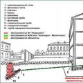 What is a hot water supply of an apartment building
 Water supply of an apartment building
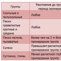 Calculation of the Load for the foundation Installed Electrical Instruments