Two re conductor under one clamp. Rules and schemes for connecting protective conductors. Rules for the implementation of the potential equalization system
By the way, dear specialists, here's another comment by my initial question, only from the ElectoC site:
my question was so -
"How many conductors can be connected under one bolt?
Can you enlighten me in a very difficult question: when, on the construction of industrial enterprises and in housing construction, electricians join for one ground bolt 2 wires, which come, for example, from two nearby shields, are they right? I believe that they are not right, because In Pue, there is a requirement (1.7.119 - Pue 7th) to the main grounding bus - "In the construction of the tire, the possibility of individual disconnection of the conductors attached to it should be provided. Disconnection should be possible only using the tool. " Does this mean that it is generally absolutely everywhere and not only on the GZSH necessarily follows one bolt to clamp only one ground wire? This opinion or understanding breaks the work of one scientist - R.N. Karyakin Dr. Tehn. Sciences, professor of the norm of the system of grounding networks, Moscow, Energoservis, 2002. There he writes so (by the way, it interprets GOST R 50571 (IEC364) including): "10.5.4. For one-to-go boring bolt (screw) forbidden to attach more than two cable tips. On a grounding (zero) bus, bolted connections of the required number of grounding, zero protective and zero working conductors should be provided.
10.5.5. It is not necessary to intentionally reinstall the hulls of electrical equipment and apparatuses installed on the ruling metal structures, switchgear, shields, cabinets, shields, machine tools, machinery and mechanisms, subject to ensuring reliable electrical contact with reassembly bases. " That is, the author it is indicated that no more than two tips can be planted under the bolt. But this he described about the shields, obviously under the bolt inside the shields, and not for wires with tips, which are placed on the ground contour bolts, which usually passes nearby. In GOST 10434-82, it is also written that under one bolt is allowed to plant 2 ground wires (exposure from GOST: (modified editors, change No. 1, 2).
2.1.12. It is recommended to connect no more than two conductors to each bolt (screw) of a flat output, unless otherwise indicated in standards or technical specifications on specific types of electrical devices.), But this GOST seems like general and at the beginning of its text, the following is written: "The requirements of the standard in terms of the permissible value of the electrical resistance and the resistance of contact compounds under through currents also apply to the contact connections in the circuits of grounding and protective conductors of steel.
The standard does not apply to electrical contact connections of electrical devices of special purpose. " There is a buysacher of opinions and everything as one documents bypass the exact indication - one or two all the same wires (tip) need to be planted under one bolt. Why in PUE 7 exactly about GZSh exactly painted, but about the rest of the ground and, in particular, about the voiced my question, nothing exactly is written? Help, please understand how to understand everything and come to any one right understanding. "
answer:
Message from Chavo.
when, on the construction of industrial enterprises and in housing construction, electrical installations are attached under one ground bolt 2 wires, which, for example, from two nearby panels, are they right?
The ban acts on the attachment of more than two conductors, and to two always please. Although I personally think that it is necessary to tighten and register - no more than one conductor.
Message from Chavo.
I believe that they are not right, because In Pue, there is a requirement (1.7.119 - Pue 7th) to the main grounding bus - "In the construction of the tire, the possibility of individual disconnection of the conductors attached to it should be provided.
And where did you find in paragraph 1.7.119 a ban on the connection of 2 conductors? Connection in the bolt of two tips does not lead to the impossibility of individual disconnection of the attached conductors. Unscrew the nut, removed the corresponding tip and wrapped back the nut. What is the problem?
Message from Chavo.
Does this mean that it is generally absolutely everywhere and not only on the GZSH necessarily follows one bolt to clamp only one ground wire?
But where did you find bans?
Message from Chavo.
The standard does not apply to electrical contact connections of electrical devices of special purpose. "
For a complete understanding, you need to get acquainted with the terms and definitions of basic concepts.
GOST 18311-80
This standard establishes the terms and definitions of concepts in the field of electrical products.
Types of electrical products, electrical devices, electrical equipment
15. Electrical product (electrical device, electrical equipment) of general purpose - electrical product (electrical engineering device, electrical equipment), satisfying the totality of technical requirements common to most cases of applications.
16. Electrical product (electrical device, electrical equipment) of special purpose - electrical product (electrical engineering device, electrical equipment), made taking into account requirements specific to a certain purpose or for certain operating conditions and (or) having special performance and (or) special design .
17. Electrical product (electrical device, electrical equipment) of a specialized destination - electrical product (electrical device, electrical equipment) of special purpose, adapted for use with only one specific object.
Message from Chavo.
There is a buysacher of opinions and everything as one documents bypass the exact indication - one or two all the same wires (tip) need to be planted under one bolt.
One bolt of no more than 2 conductors (tips).
Message from Chavo.
Why in PUE 7 exactly about GZSh exactly painted, but about the rest of the ground and, in particular, about the voiced my question, nothing exactly is written?
You confused the number of conductors with individual detachment.
In general, Comrade Indicates that 2 conductor under the bolt is not forbidden !!! Well, about one conductor under one bolt on GZSH - it's only GZSH touches! Well, yes, most likely he is right ... and Volk right !!! I hope our dialogue now completely revealed an understanding of the topic raised by me! Let it become useful for everyone doubters))) I, too, for tightening the requirements - one wire for one bolt! It is right and easy to remember)))
3.3. Requirements for protective grounding
3.3.1. The element for the grounding should be equipped with products, the purpose of which does not require the implementation of a person's protection method from electric shock, corresponding to classes II and III.
It is allowed to perform without a ground element and do not ground the following products:
intended for installation in inaccessible, without the use of special means, places (including inside other products);
intended for installation only on grounded metal structures, if the stable electrical contact of contacting surfaces is ensured and the requirement of claim 3.3.7;
parts of which can not be under alternating voltage above 42 V and under constant voltage above 110 V;
grounding which is not allowed by the principle of action or appointment of the product.
(Modified edition, change No. 1, 3).
3.3.2. Welded or threaded connections should be applied to attach a grounding conductor.
In coordination with the consumer, the grounding conductor can join the product using a soldering or pressing performed by a special tool, device or machine.
3.3.3. Grounding clamps must comply with the requirements of GOST 21130-75.
It is not allowed to ground bolts, screws, studs that perform the role of fastening parts.
3.2.2-3.3.3. (Modified edition, change No. 1).
3.3.4. Bolt (screw, hairpin) To attach a grounding conductor to be made of metal, resistant to corrosion, or coated with a metal that protects it from corrosion, and the contact part should not have surface color.
(Modified edition, change No. 4).
3.3.5. Bolt (screw, hairpin) for grounding should be placed on the product in a safe and convenient place for connecting a grounding conductor. Near the place in which the grounding of the grounding conductor must be accomplished, provided for by paragraph 3.3.2, must be placed in any way undischable during operation of grounding sign. Sizes of the sign and method of its implementation - according to GOST 21130-75, and for lamps - according to GOST 17677-82.
Around the bolt (screw, studs) should be a contact pad to attach a grounding conductor. The site should be protected from corrosion or made from anti-corrosion metal, and not have surface color.
Measures should be taken against the possible weakening of contacts between the grounding conductor and the bolt (screw, with a height) for grounding (with knotting, spring washers).
The diameters of the bolt (screw, studs) and the contact pad must be selected by the current (see Table 1).
Table 1
Rated current electrotechnical nominal diameter of the thread for the scene of the contact site of the connection site, mm
products, and attachments, not less on the surface plane elevated relative to the surface
St. 4 to 6 m 3 10 7
"6" 16 m 3.5 11 8
"16" 40 m 4 12 9
"40" 63 m 5 14 11
"63" 100 m 6 16 12
"100" 250 m 8 20 17
"250" 630 m 10 25 21
"630 m 12 28 24
Notes:
1. On the currents above 250 A, it is allowed instead of one bolt to put two, but with a total cross section of at least required.
As a current when choosing the smallest diameter of the bolt for consumers and electromagnetic energy converters, take the current value. The product consumed from the source (network), for sources of electromagnetic energy - the value of the nominal load current.
2. For sources of electromagnetic energy having several nominal currents, the selection of the diameter of the bolt should be made by the largest of these currents.
(Modified editors, change No. 1, 3, 4).
3.3.6. In case the size of the product is small, and also if the grounding bolt (screw) is installed using the welding of its head, the necessary surface of contact in connection with the ground conductor is allowed to provide with the help of washers. The material washer must comply with the same requirements as the material of the grounding bolt (screw, studs).
3.3.7. The product should be provided with an electrical connection of all the available touches of metal inadvertent parts of the product, which may be energized with elements for grounding.
The resistance value between the grounding bolt (screw, the heel) and each accessible touch of the metal inclusive part of the product, which may be under voltage, should not exceed 0.1 Ohm.
3.3.8. The elements for grounding should be equipped with the following metal inadvertent parts of products to be grounded:
shells, hulls, cabinets;
frames, frames, clips, racks, chassis, bases, panels, plates and other parts of products that may be under voltage during isolation damage.
It is allowed not to perform elements for grounding in the following parts of the product (from among those listed above):
products of products intended for installation on grounded panels, metal walls of camshafts, in cabinets;
inactive metal parts of a product that have electrical contact with grounded parts, subject to the requirements of clause 3.3.7;
parts fixed in an insulating material or passing through it and isolated both from grounded and from parts under the voltage (provided that during the work of the product, they cannot be energized or coming into contact with grounded parts).
3.3.9. Each part of the product equipped with an element for grounding must be made so that:
there was the possibility of its independent attachment to the earthing or grounding line through a separate branch, so that when removing any grounded part of the product (for example, for current repairs), the earthing chain of other parts was not interrupted;
there was no need for a sequential connection of several grounded parts of the product.
3.3.10. Grounding of parts of products installed on moving parts should be performed by flexible conductors or sliding contacts.
3.3.11. If there is a metal shell, an element for its grounding should be located inside the shell.
It is allowed to perform it outside the shell or perform several elements both inside and outside the shell.
(Modified edition, change No. 1).
3.3.12. Obtaining electrical contact between the removable and grounded (non-removable) parts of the shell must be directly pressed by the removable part to the non-removable; At the same time, in places in contact with the surface of the removable and non-removable parts of the shell, they must be protected from corrosion and are not covered with electrically insulating layers of varnish, paints or enamel.
An electrical connection of the removable part of the shell with a non-removable grounded is allowed through the screws or bolts, provided that 1-2 screws or bolts have an anti-corrosion metal coating, and there is no electrically insulating layer of varnish between the heads of these screws or bolts and the removable metal part of the shell. Enamels or between them are installed toothed washers that destroy the electrical insulating layer for electrical connection or without gears, subject to the attachment of the removable part to a non-removable grounded six or more bolts (or screws) and the absence of electrical connections on removable parts.
The gears are allowed to apply also for the electrical connection of the grounded shell and the equipment mounted in the product, and set them to ground the items of the product through the bolted connections.
(Modified edition, change No. 3).
3.3.13. The requirements listed in clause 3.3 do not belong to the products intended for operation only in areas with a tropical climate and made according to GOST 15151-69, GOST 9.048-89.
Rules and schemes for connecting protective conductors of re and equalization of potentials
In all buildings, the group network lines deployed from group, storey and apartment plates to lamps of general lighting, plug sockets and stationary electrical receivers must be performed by three-wires (phase - L, zero working - N and zero protective conductors).
The zero working and zero protective conductors of various group lines is not allowed.
Zero working and zero protective conductors are not allowed to connect under the overall contact clamp. The selection of the sections of the conductors should be carried out according to the requirements of the respective PUE chapters.
Single-phase two- and three-wire lines, as well as three-phase four- and five-wire lines when powering single-phase loads, should have a cross section of zero working N conductors equal to the sching of phase conductors.
Three-phase four- and five-wire lines in powering three-phase symmetric loads must have a cross section of zero working N wires equal to the sectional conductivity, if the phase conductors have a cross section of up to 16 mm2 by copper and 25 mm2 by aluminum, and at large sections - at least 50 % Section of phase conductors, but not less than 16 mm2 on copper and 25 mm2 by aluminum.
The PEN conductor cross section should be no less than the cross section of n conductors and at least 10 mm2 on copper and 16 mm2 by aluminum, regardless of the sections of phase conductors.
The cross section of the conductors should be equal to the secting of the phase when the last to 16 mm2, 16 mm2 during the sections of the phase conductors from 16 to 35 mm2 and 50% of the sections of the phase conductors during large sections. The cross section of the conductor not included in the cable must be at least 2.5 mm2 - in the presence of mechanical protection and 4 mm2 - in its absence.
Changes connecting protective conductors re
Combined zero and working conductor Pen is divided into zero protective re and zero working N conductors in the introductory device.
Execution of the grounding system TN-C-S
The letters used in the figures have the following meaning. The letter is the character - the nature of the power supply of the power supply: T - the direct connection of one point of the current-generating parts of the power supply to the ground; N is the immediate connection of open conductive parts with a power supply point of the power source (neutral is usually ground in alternating current systems).
Subsequent letters determine the device of zero working and zero protective conductors: S - the functions of zero protective (re) and zero working (N) are provided by separate conductors; C - the functions of zero protective and zero working conductors are combined in one conductor (REN conductor).
Zero working and zero protective conductors are not allowed to connect under the overall contact clamp. The meaning of this requirement is necessary, in order to ensure the conditions of electrical safety, preserving the connection of the protective conductor with the ground in the event of a destruction (burnout) of the contact clamp.
Examples of connecting the Conductor Repends and N to Pen on store or apartment panel

Examples of connecting the conductors of re and n to Pen
Rules for the implementation of the potential equalization system.
To ensure the conditions of electrical safety in a particular electrical installation, the system of equalizing potentials is important. The rules for performing the potential equalization system are determined by the IEC 364-4-41 and PUE (7th ed.). These rules provide for the connection of all the conductors to be grounded to the total tire.
An example of the performance of the potential equalization system.
Such a solution avoids the flow of various unpredictable circulating currents in the grounding system, causing the occurrence of the potential difference on individual elements of the electrical installation.

An example of a system of equalizing potentials in the electrical installation of a residential building
Recently, with an increase in the equipment of modern residential buildings and industrial buildings with various electrical appliances and the constant development of their electrical installations, the phenomena of accelerated corrosion of pipelines of water supply and heating systems has become increasingly observed. In a short time - from six months to two years - on pipes both underground and air gaskets are formed point fists, rapidly increasing in size. The cause of accelerated point (pitting) corrosion of pipes in 98% of cases is the flow of wandering currents.
The use of the UZO in a complex with a properly performed system equalization system allows you to limit and even eliminate the flow of leakage currents, wandering currents on the conductive elements of the building structure, including on pipelines.
The scandalous question is grounding (rewarding)
Speaking in general, it can be noted that the great and terrible power of electricity has long been described, calculated, listed in thick tables. The regulatory framework that determines the paths of the sinusoidal electrical signals of the frequency of 50 Hz can imagine any neophyte to horror in its volume. And despite this, any frequenter of technical forums has long been known - there is no more scandalous question than grounding.
The mass of contradictory opinions actually contributes to the establishment of truth. Moreover, this question is actually serious, and requires more close consideration.
Basic concepts
If you omit the entry of the "Bible of the Electrician" (PUE), then to understand the grounding technology, you need to appeal (for starters) to chapter 1.7, which is called "grounding and protective measures of electrical safety".
In paragraph 1.7.2. Pue says:
Electrical installations regarding electrical safety measures are divided into:
- electrical installations above 1 kV in networks with effectively grounded neutral (with large closure currents to earth) ,;
- electrical installations above 1 kV in networks with an isolated neutral (with small ground closure currents);
- electrical installations up to 1 kV with deaf-grounded neutral;
- electrical installations up to 1 kV with neutral isolated.
In the overwhelming majority of residential and office houses of Russia, a deaf-rigged neutral is used. Paragraph 1.7.4. Person:
A deaf-winded neutral is called a transformer neutral or a generator attached to a grounding device directly or through a small resistance (for example, through current transformers).
The term is not completely understandable at first glance - neutral and grounding device at every step in a popular science press are not found. Therefore, below all incomprehensible places will be gradually explained.
We introduce some terms - so it will be possible to at least speak in one language. Perhaps items will seem "pulled out of the context". But PUE is not fiction, and such separate use should be quite reasonable - as applying individual articles of the Criminal Code. However, the original PUE is fully accessible both in bookstores and on the network - you can always contact the original source.

Fig. 1. The difference between the protective ground and the protective "zero"
So, directly from the PUE terms should be simple output. The differences between the "Earth" and "zero" are very small ... At first glance (how many copies are broken at this place). At the very least, they must be connected (or even can be performed "in one bottle"). The question is only where and how it is done.
Along the way, we note paragraph 1.7.33.
Grounding or changing electrical installations should be performed:
- at a voltage of 380 V and above alternating current and 440 V and above DC - in all electrical installations (see also 1.7.44 and 1.7.48);
- at rated voltages above 42 V, but below 380 V AC and above 110 V, but below 440 V DC - only indoors with increased danger, especially dangerous and in external installations.
In other words, grounding or reinforcing the device connected to the voltage 220 volts of alternating current is not necessarily. And there is nothing particularly amazing - the third wire in ordinary Soviet outlets is really not observed. It can be said that the Eurostandard who comes into practice (or a new edition of PUE) is better, more reliable, and safer. But according to the old Pue, we lived in the country dozens of years ... and most importantly, houses were built by whole cities.
However, when it comes to grounding, it is not only in supply voltage. A good illustration of this - VNC 59-88 (State Architectures) "Electrical Equipment of residential and public buildings. Design standards" Exposure from chapter 15. Grounding (reinstallation) and protective safety measures:
15.4. For grounding (reinforcement) of metal buildings of household air conditioners, stationary and portable household appliances of class I (not having double or enhanced insulation), household electrical appliances with power of SV. 1.3 kW, housing of three-phase and single-phase electric stoves, cooking boilers and other thermal equipment, as well as metal inadvertent parts of the technological equipment of rooms with wet processes, should be used a separate conductor with a sequence equal to the phase deposited from the shield or a shield to which this electr receiver is connected, And in the lines of medical equipment, - from the village or rching the building. This conductor joins the zero power conductor. The use for this purpose of the working zero conductor is prohibited.
It turns out a regulatory paradox. One of the results visible on the household level was the acquisition of the washing machines "Vyatka-Avtomat" by a single-core aluminum wire with the requirement to ground (with the hands of a certified specialist).
And one more interesting point:. 1.7.39. In electrical installations up to 1 kV with a deaf-free neutral or a deaf-free output of a single-phase current source, as well as with a deaf-rigged midpoint in three-wire DC networks, a rejection must be made. Application in such electrical installations of grounding of electrical receivers without the reassembly is not allowed.
Almost this means - you want to "ground" - first "joined". By the way, it is directly related to the famous "envelope" question - which is an inexplicable reason for an unknown reason, it is erroneously considered better reassembly (grounding).
Ground parameters
The next aspect that must be considered - numeric grounding parameters. Since physically it is nothing more than a conductor (or many conductors), then its main characteristic will be resistance.
1.7.62. The resistance of the grounding device to which the neutrals of generators or transformers are attached or the conclusions of a single-phase current source, at any time of the year there must be no more than 2, 4 and 8 ohms, respectively with linear stresses 660, 380 and 220 in the source of three-phase current or 380, 220 and 127 In a source of single-phase current. This resistance must be ensured taking into account the use of natural earthingers, as well as earthing repetitioners of the zero wire of the VL to 1 kV with the number of exhaust lines of at least two. At the same time, the impedance of the earthing, located in the immediate vicinity of the neutral of the generator or the transformer or the output of the source of a single-phase current, should be no more than: 15, 30 and 60 ohms, respectively, with linear voltages 660, 380 and 220 in the source of three-phase current or 380, 220 and 127 In a source of single-phase current.
For less voltage is permissible greater resistance. This is understandable - the first goal of grounding is to ensure the safety of a person in the classical case of the "phase" hit on the electrical installation case. The smaller the resistance, the smaller part of the potential may be "on the case" in the event of an accident. Consequently, first of all, it is necessary to reduce the danger to higher voltage.
Additionally, it must be borne in mind that the grounding also serves to normal fuses. For this, it is necessary that the line with a test "on the body" significantly changed the properties (first of all resistance), otherwise the operation will not happen. The greater the power of the electrical installation (and consumed voltage), the lower its impedance, and, accordingly, should be lower than the ground resistance (otherwise the fuses will not work from a minor change in the total chain resistance).
The next normed parameter is the cross section of the conductors.
1.7.76. Grounding and zero protective conductors in electrical installations up to 1 kV must have dimensions of not least given in Table. 1.7.1 (see also 1.7.96 and 1.7.104).
It is not advisable to bring the entire table, enough exposure:
For uninsulated copper, the minimum cross section is 4 square meters. mm, for aluminum - 6 square meters. mm. For isolated, respectively, 1.5 square meters. mm and 2.5 square meters. mm. If ground conductors go in one cable with power wiring, their cross-section can be 1 kV. mm for copper, and 2.5 square meters. mm for aluminum.
Grounding in a residential building
In the usual "household" situation, the users of the power grid (i.e. tenants) are dealt with only with a group network (7.1.12 Pue. Group network - network from shields and distribution points to lamps, plug sockets and other electrical receivers). Although in old houses where shields are installed directly in the apartments, they have to face part of the distribution network (7.1.11 Pue. Distribution network - a network from Wu, SER, GRACH to distribution points and panels). It is advisable to understand well, because often "zero" and "land" differ only to the place of compound with the main communications.
From this in PUE formulated the first ground rule:
7.1.36. In all buildings, the group network lines deployed from group, storey and apartment plates to lamps of general lighting, plug sockets and stationary electrical receivers must be performed by three-wires (phase - L, zero working - N and zero protective conductors). The zero working and zero protective conductors of various group lines is not allowed. Zero working and zero protective conductors are not allowed to connect on the panels under the general contact clamp.
Those. From a flood, apartment or group flap, you need to lay 3 (three) wires, one of which is a protective zero (not at all the earth). What, however, does not prevent it at all to use it for grounding the computer, the cable screen, or the "tail" of lightning protection. It seems to be simple, and it is not entirely clear, why delve into such difficulties.
You can look at your home socket ... and with a probability of about 80% not to see there of third contact. What is the difference between zero working and zero protective conductors? In the shield they are connected on the same tire (even if not at one point). What will happen if used in this situation a working zero as a protective?
It is difficult to assume that the negligent electrician confuses the phase and zero panel. Although it is constantly frightened by users, but it is impossible to be mistaken in any condition (although there are unique cases). However, the "working zero" goes on numerous strokers, probably passes through several distribution boxes (usually small, round, mounted in the wall near the ceiling).
Customize the phase with zero there is much easier (I myself did more than once). And as a result, 220 volts will be 220 volts on the housing of the wrong "ground" device. Or even easier - the contact is contaminated somewhere in the chain - and almost the same 220 will be held on the body through the load of the electro protector (if it is an electric stove for 2-3 kW, it will not seem little).
For the human protection function, it is directly saying that there is no reasonable situation. But to connect the grounding ground, the APC type is not fatal, since the high-voltage junction is installed there. However, to recommend this method would be definitely incorrectly in terms of security. Although it is necessary to recognize that this norm is disturbed very often (and as a rule without any adverse effects).
It should be noted that the implacability of working and protective zero is approximately equal. Resistance (to the connecting bus) is slightly different, and this is perhaps the main factor affecting the flow of atmospheric tip.
From further text PUE, it can be noted that it is necessary to attach everything in the house to zero protective conductor:
7.1.68. In all rooms, it is necessary to attach the open conductive parts of the lamps of general lighting and stationary electrical receivers (electric plates, boiling cells, household air conditioners, an electric folothene, etc.) to zero protective conductor.
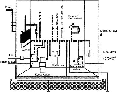
In general, it is easier to present the following illustration:
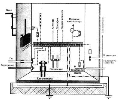
Fig. 2. Grounding scheme.
The picture is pleased with the unusual (for everyday perception). Literally everything that is in the house must be grounded on a special tire. Therefore, the question may arise - after all, they lived without this dozens of years, and everyone is alive, healthy (and thank God)? Why everything is so serious? The answer is simple - consumers of electricity becomes more, and they are more and more powerful. Accordingly, the risks of the lesion grow.
But the dependence of safety and value is statistical, and no one has canceled savings. Therefore, blindly put on the perimeter of the apartment copper strip of a decent section (instead of a plinth), the crying on it everything, right up to the metal legs of the chair, is not worth it. How not to walk in the fur coat in the summer, and constantly carry a motorcycle helmet. This is an adequacy question.
Also in the region of an unscientific approach it should be attributed to an independent digging of trenches under the protective contour (in the city house, in addition to problems, it will not bring anything obviously). And for those who want to still experience all the charms of life - in the first chapter of PUE there are standards for the manufacture of this fundamental structure (in the literal sense of the word).
Summarizing the above, you can draw the following practical conclusions:
- If the group network is made in three wires, a protective zero can be used for grounding / reassembly. He, in fact, is invented.
- If the group network is completed with two wires, it is desirable to start a protective zero wire from the nearest panel. The wire cross section should be more than phase (you can more accurately cope in PUE).
To ensure the safety of people in networks up to 1000 in a deaf neutral grounding, a zero is applied. In these networks, grounding equipment equipment without metallic communications with a transformer or generator is prohibited. In the circuit of zero wires used to bottom, there should be no fuses and disconnecting devices.
All engineering equipment joins the line of reassembly in parallel (see Fig. 1). Sequential downstream is prohibited.
The attachment of the reinforcing conductors to the equipment is performed welding or under the bolt. In all places where it is possible to join temporary grounds for repair work, there must be special bolts or stripped and lubricated vacuine places.
Zero output of the generator or transformer must be attached to the grounded zero tire of the distribution shield. The zero tire is attached to the shield frame on the insulators. Frames of distribution shields of substations are connected by tires with a ruling trunk.
Power shields and power camshafts are joined by attaching to the zero wire of the supply line, and in the absence of such a special tire of grounding from the substation should be laundered. In addition, it is necessary to connect them with the shells of all cables, electrical wiring pipes and grounded pipelines and metal structures nearby.
Attaching zero and grounding wires inside shields and cabinets is made to the grounding bus with bolts. Under one bolt is allowed to connect no more than two wires.
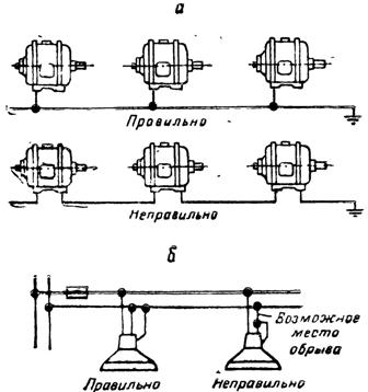
Fig. 1. Attaching the parts of the electrical installation to the Network Network: A - Electric Motors, B - Lamps
Electric motors and starting equipment are joined by pipes, in which the feed wires are laid, or with the help of individual reinforcing conductors (Fig. 2). It is allowed instead of reducing individual devices or engines to securely ground the machine housing on which they are installed.
The enclosures of the lamps are joined by attaching to zero wire or grounded design. A reinforcing conductor must be connected by one end under the grounding bolt on the reinforcement, and the second end - to a grounded design or zero wire (Fig. 1).
Methods for reducing different types of electrical equipment are indicated in Fig. 2-7.
Portable electrical receivers are grounded using separate copper veins with a cross section of at least 1.5 mm2 in a common shell with phase cores.

Fig. 2. Raning the engine housing: 1 - steel pipe electrical wiring, 2 - flexible output, 3 - jumper, 4 - contact checkbox 25x30x3 mm, 5 - ground bolt
Plug sockets for portable current collectors must have a grounding contact that is connected to a fork before connecting to the current contacts.
The hulls of mobile mechanisms receiving electricity from stationary sources or mobile power plants should have a metal connection with a rejection or grounding of these power sources.

Fig. 3. Connection of a metal case with a steel pipe of the wiring: A - the diameter of the hole in the housing corresponds to the diameter of the pipe, b - the diameter of the hole in the body is less than the diameter of the pipe, B - the diameter of the hole in the housing is greater than the outer diameter of the pipe, 1 - metal case, 2 - steel pipe Electric wiring, 3 - Nut installation K480-K486, 4 - locking, 5 - Coupling Direct, 6 - Fortorca, 7 - nipple double.
The housings of single-phase welding transformers are joined by using a third core in a three-core power cable.
Metal shells of wires and cables, armor, flexible metal sleeves, steel pipes of wiring should be reeling.

Fig. 4. Related by single cable structures: A - painted, welded to mortgage elements, b - galvanized, fixed using brackets, 1 - mortgage element, 2 - cable design, 3 - bracket, 4 - conductor, joined at the beginning and end of the route A reinforcing highway is welded to each mortgage element or bracket.

Fig. 5. Raning cable structures in the channels: 1 - a rearing conductor is welded to each mortgage element and at the beginning and end of the track joins the reinforcement highway, 2 - mortgage element
Note. With double-sided location of cable structures, the conductive conductors at the beginning and end of the track are connected by jumpers with welding

Fig. 6. Raning of welded trays, laid on the wall: 1 - Bolt M6x26, 2 - Nut M8, 3 - washer

Fig. 7. Replacement of the carrier cable: A - for flexible current supply, b - for suspension cable or cable wiring wires, 1 - carrier cable, 2 - Cable with insulating shell, 3 - sleeve Note. Breaking cable, with both ends of the reinforcement line with welding or sleeve.
The shell and armor of cables are entered at both ends of the jumper attachment paths from a flexible multi-breed copper conductor, the cross section is indicated below.
Metal supports and reinforced concrete reinforcement fittings are connected to a zero grounded wire.
In residential and public buildings, be sure to replace the metal hulls of household stationary electric stoves, boiling cards and portable electrical devices with a capacity of more than 1.3 kW, as well as metal electrical equipment and electrical wiring pipes, located in basements, undergrounds, on stairwells, public restrooms, shower etc. Rooms.
In rooms without increased danger, as well as in the kitchens, the station of stationary installed equipment (with the exception of electric stoves), as well as portable electrical appliances with a capacity of up to 1.3 kW (irons, tiles, kettles, vacuum cleaners, washing machines, and so para) required.
In the bathrooms of residential and public buildings, in baths, medical institutions, etc. Metal baths for baths and shower pallets must be connected by metal conductor with water pipes for equalizing the potential (Fig. 8). Pipes of gas pipelines use for equalization of the potential.
Fig. 8. Grounding the metal bath case by connection with water pipes: 1 - tap pipe, 2 - grounding conductor, 3 - Homut, 4 - washer, 5 - washer, spring cut, 5 - bolt, 7 - nut, 8 - tip, 9 - Screw, 10 - Bath hull, 11 - screw.
In public buildings, premises with increased danger and especially dangerous (production facilities of catering enterprises, boiler rooms, refrigerators, production workshops of household services, workshops of schools, bathrooms, ventkamera, air conditioners, machinery of elevators, pumping stations, thermal points, and t . dt.) All stationary and portable electrical receivers that do not have double insulation, steel pipes of electrical wiring, metal housings of shields and cabinets should be reeling. Plug sockets on a voltage of 220 and 380 B to connect portable and mobile electrical receivers must have protective contacts connected to zero wire.
In rooms without increased danger having suspended ceilings, lamps and metal ceilings designs must be reached.
In entertainment enterprises, metal structures and housings of all scene devices are subject to rejection, as well as the housing of all shields in all rooms.
The metal corps of projectors and sound operating equipment should be found in separate insulated wires and are additionally attached to a separate ground located near the room of the hardware.
 What is a hot water supply of an apartment building
 Water supply of an apartment building
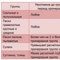 Calculation of the Load for the foundation Installed Electrical Instruments