Electronic circuits for beginners. Practical diagrams of different devices. Graphics of other elements
Learning to read electrical schematic diagrams
I already talked about how to read schematic diagrams in the first part. Now I would like to reveal this topic more fully so that even a beginner in electronics does not have any questions. So let's go. Let's start with the electrical connections.
It is no secret that in the circuit, any radio component, for example, a microcircuit, can be connected by a huge number of conductors with other elements of the circuit. In order to free up space on the schematic diagram and remove the "repeating connecting lines" they are combined into a kind of "virtual" bundle - they denote a group communication line. On the diagrams group communication line denoted as follows.

Take a look at an example.

As you can see, such a group line is thicker than other conductors in the circuit.
In order not to get confused, where which guides go, they are numbered.
In the figure, I marked the connecting wire under the number 8 ... It connects pin 30 of DD2 chip and 8 contact of XP5 connector. Also, pay attention to where the 4 wire goes. For XP5 connector, it is connected not with pin 2 of the connector, but with pin 1, therefore it is indicated on the right side of the connecting conductor. The 5th conductor is connected to the 2nd contact of the XP5 connector, which goes from the 33rd output of the DD2 microcircuit. Note that connecting conductors with different numbers are not electrically connected to each other, and on a real printed circuit board they can be spaced across different parts of the board.
The electronic filling of many devices consists of blocks. And, therefore, detachable connections are used to connect them. This is how detachable connections are indicated on the diagrams.

XP1 - this is a fork (aka "Dad"), XS1 - this is a socket (aka "Mom"). All together this is "Dad-Mom" or connector X1 (X2 ).
Also, electronic devices can have mechanically connected elements. Let me explain what this is about.
For example, there are variable resistors that have a built-in switch. I talked about one of these in the article about variable resistors. This is how they are indicated on the schematic diagram. Where SA1 - switch, and R1 - variable resistor. The dotted line indicates the mechanical connection of these elements.

Previously, such variable resistors were very often used in portable radios. When you turn the volume control knob (our variable resistor), the contacts of the built-in switch first closed. Thus, we turned on the receiver and immediately adjusted the volume with the same knob. Note that the variable resistor and the switch do not have an electrical contact. They are only mechanically connected.
The same situation is with electromagnetic relays. The relay coil itself and its contacts are not electrically connected, but mechanically they are connected. We supply current to the relay coil - the contacts close or open.

Since the control part (relay winding) and the executive part (relay contacts) can be separated on the schematic diagram, their connection is indicated by a dashed line. Sometimes a dotted line do not draw at all, and the contacts simply indicate the belonging to the relay ( K1.1) and contact group number (K1. 1 ) and (K1. 2 ).
Another rather illustrative example is the volume control of a stereo amplifier. Two variable resistors are required to control the volume. But adjusting the volume in each channel separately is impractical. Therefore, double variable resistors are used, where two variable resistors have one control shaft. Here's an example from a real-world circuit.

In the figure, I highlighted two parallel lines in red - they indicate the mechanical connection of these resistors, namely, that they have one common control shaft. You may have already noticed that these resistors have a special reference designation R4. 1 and R4. 2 ... Where R4 is a resistor and its serial number in the circuit, and 1 and 2 point to the sections of this dual resistor.
Also, the mechanical connection of two or more variable resistors can be indicated by a dashed line, and not by two solid ones.

Note that electrically these variable resistors have no contact between themselves. Their pins can only be connected in a circuit.
It is no secret that many radio equipment units are sensitive to the effects of external or "adjacent" electromagnetic fields. This is especially true in transceiver equipment. To protect such units from the effects of unwanted electromagnetic influences, they are placed in a screen, shielded. As a rule, the shield is connected to the common wire of the circuit. On the diagrams, it is displayed like this.

This is where the outline is escaping 1T1 , and the screen itself is depicted by a dash-dotted line, which is connected to a common wire. The shielding material can be aluminum, metal housing, foil, copper plate, etc.
And this is how shielded communication lines are designated. The figure in the lower right corner shows a group of three shielded conductors.

Coaxial cable is designated in a similar way. Take a look at its designation.
In reality, a shielded wire (coaxial) is an insulated conductor that is covered or wrapped on the outside with a screen of conductive material. This can be copper braid or foil coating. The screen, as a rule, is connected to a common wire and thereby conducts electromagnetic interference and pickup.
Duplicate items.
There are frequent cases when absolutely identical elements are used in an electronic device and it is impractical to clutter up the circuit diagram with them. Here, take a look at this example.

Here we see that the circuit contains resistors R8 - R15 of the same value and power. Only 8 pieces. Each of them connects the corresponding output of the microcircuit and a four-digit seven-segment indicator. In order not to indicate these repeating resistors on the diagram, they were simply replaced with bold dots.
One more example. Crossover (filter) circuit for the loudspeaker. Pay attention to how instead of three identical capacitors C1 - C3, only one capacitor is indicated on the diagram, and the number of these capacitors is marked next to it. As you can see from the diagram, these capacitors must be connected in parallel to obtain a total capacitance of 3 μF.

Likewise with capacitors C6 - C15 (10 μF) and C16 - C18 (11.7 μF). They must be connected in parallel and installed in place of the designated capacitors.
It should be noted that the rules for the designation of radio components and elements on the diagrams in foreign documentation are somewhat different. But, for a person who has received at least basic knowledge on this topic, it will be much easier to understand them.
Content:Each electrical circuit consists of many elements, which, in turn, also include various parts in their design. The most striking example is household appliances. Even an ordinary iron consists of a heating element, a temperature controller, an indicator light, a fuse, a wire and a plug. Other electrical appliances have an even more complex design, complemented by various relays, circuit breakers, electric motors, transformers and many other parts. An electrical connection is created between them, ensuring the full interaction of all elements and the fulfillment of each device for its purpose.
In this regard, the question very often arises of how to learn to read electrical circuits, where all components are displayed in the form of conventional graphic symbols. This problem is of great importance for those who regularly deal with electrical installations. Correct reading of the diagrams makes it possible to understand how the elements interact with each other and how all work processes proceed.
Types of electrical circuits
In order to properly use electrical circuits, you need to familiarize yourself in advance with the basic concepts and definitions affecting this area.
Any scheme is performed in the form of a graphic image or drawing, which, together with the equipment, displays all the connecting links of the electrical circuit. There are various types of electrical circuits that differ in their intended purpose. Their list includes primary and secondary circuits, alarm systems, protection, control and others. In addition, there exist and are widely used principled and, full-line and detailed. Each of them has its own specific characteristics.
Primary circuits include circuits through which the main technological voltages are supplied directly from sources to consumers or receivers of electricity. Primary circuits generate, convert, transmit and distribute electrical energy. They consist of a main circuit and circuits that supply their own needs. Main circuit circuits generate, transform and distribute the main flow of electricity. Auxiliaries circuits support the operation of the main electrical equipment. Through them, the voltage is supplied to the electric motors of the installations, to the lighting system and to other areas.
Secondary circuits are those in which the supplied voltage does not exceed 1 kilowatt. They provide the performance of the functions of automation, control, protection, dispatching service. Electricity is monitored, measured and recorded through the secondary circuits. Knowing these properties will help you learn how to read electrical circuits.
Full line diagrams are used in three-phase circuits. They represent electrical equipment connected to all three phases. Single line diagrams show equipment placed in only one middle phase. This difference is necessarily indicated on the diagram.

The schematic diagrams do not indicate secondary elements that do not perform basic functions. This makes the image simpler, allowing a better understanding of the operation of all equipment. Wiring diagrams, on the contrary, are performed in more detail, since they are used for the practical installation of all elements of the electrical network. These include single-line diagrams displayed directly on the building plan of the facility, as well as cable routing diagrams with transformer substations and distribution points plotted on a simplified master plan.
In the process of installation and commissioning, detailed circuits with secondary circuits have become widespread. They are allocated additional functional subgroups of circuits associated with switching on and off, individual protection of any area and others.
Designations in electrical diagrams
Each electrical circuit contains devices, elements and parts, which together form a path for electric current. They are distinguished by the presence of electromagnetic processes associated with electromotive force, current and voltage, and described in physical laws.

In electrical circuits, all components can be conditionally divided into several groups:
- The first group includes devices that generate electricity or power supplies.
- The second group of elements converts electricity into other forms of energy. They serve as receivers or consumers.
- The components of the third group provide the transfer of electricity from one element to another, that is, from the power source to the electrical receivers. This also includes transformers, stabilizers and other devices that provide the required quality and voltage level.
Each device, element or part corresponds to a conventional designation used in graphic representations of electrical circuits, called electrical circuits. In addition to the basic symbols, they show the power lines connecting all these elements. The sections of the chain along which the same currents flow are called branches. The places of their connections are nodes, indicated on electrical diagrams in the form of dots. There are closed paths of current movement, covering several branches at once and called circuits. The simplest electrical circuit diagram is single-circuit, and complex circuits consist of several circuits.
Most circuits consist of various electrical devices with different modes of operation, depending on the value of the current and voltage. In idle mode, there is no current in the circuit at all. Sometimes such situations arise when the connections are broken. In the nominal mode, all elements operate with the current, voltage and power that are indicated in the device's passport.

All components and symbols of electrical circuit elements are displayed graphically. The figures show that each element or device has its own conventional icon. For example, electrical machines can be depicted in a simplified or expanded manner. Depending on this, conditional graphic schemes are also built. Single line and multi line views are used to show the winding leads. The number of lines depends on the number of pins, which will be different for different types of machines. In some cases, for the convenience of reading the diagrams, mixed images can be used, when the stator winding is shown in an expanded view, and the rotor winding is shown in a simplified one. Others are done in the same way.
They are also carried out in a simplified and expanded, single-line and multi-line methods. The way of displaying the devices themselves, their terminals, connections of windings and other constituent elements depends on this. For example, current transformers use a thick dotted line to represent the primary winding. For the secondary winding, a circle can be used in the simplified method or two semicircles in the expanded display method.

Graphic images of other elements:
- Contacts. They are used in switching devices and contact connections, mainly in circuit breakers, contactors and relays. They are divided into make, break and switch, each of which has its own graphic pattern. If necessary, it is allowed to display contacts in a mirror-inverted form. The base of the moving part is marked with a special unshaded point.
- ... They can be single-pole and multi-pole. The base of the moving contact is marked with a dot. For circuit breakers, the type of release is indicated in the image. Switches differ in the type of impact, they can be push-button or travel, with break and make contacts.
- Fuses, resistors, capacitors. Each of them has specific icons. Fuses are shown as a rectangle with taps. Fixed resistors can have an icon with or without taps. The moving contact of a variable resistor is indicated by an arrow. The capacitor figures show constant and variable capacitance. There are separate images for polar and non-polar electrolytic capacitors.
- Semiconductor devices. The simplest of them are diodes with a pn junction and one-sided conductivity. Therefore, they are depicted in the form of a triangle and an electrical communication line crossing it. The triangle is the anode and the dash is the cathode. Other types of semiconductors have their own designations defined by the standard. Knowledge of these graphic drawings makes it much easier for dummies to read electrical diagrams.
- Sources of light. Available on almost all electrical circuits. Depending on their purpose, they are displayed as lighting and signal lamps using the corresponding icons. When displaying signal lamps, it is possible to shade a certain sector, corresponding to a low power and a small luminous flux. In alarm systems, along with light bulbs, acoustic devices are used - electric sirens, electric bells, electric horns and other similar devices.
How to read wiring diagrams correctly
A schematic diagram is a graphical representation of all elements, parts and components between which an electronic connection is made using live conductors. It is the basis for the development of any electronic devices and electrical circuits. Therefore, every novice electrician should first of all master the ability to read a variety of circuit diagrams.

It is the correct reading of electrical circuits for beginners that makes it possible to master well how it is necessary to connect all the parts in order to get the expected end result. That is, the device or circuit must fully perform its assigned functions. For the correct reading of the schematic diagram, it is necessary, first of all, to familiarize yourself with the symbols of all its constituent parts. Each detail is marked with its own conventional graphic designation - UGO. Typically, such symbols reflect the general design, characteristic features and purpose of a particular element. The most striking examples are capacitors, resistors, speakers, and other simple parts.
It is much more difficult to work with components represented by transistors, triacs, microcircuits, etc. The complex design of such elements also implies a more complex display of them on electrical circuits.

For example, each bipolar transistor has at least three terminals - base, collector and emitter. Therefore, for their conventional representation, special graphic symbols are required. This helps to distinguish between parts with individual basic properties and characteristics. Each symbol carries certain encrypted information. For example, bipolar transistors can have a completely different structure - p-p-p or p-p-p, so the images on the diagrams will also be noticeably different. It is recommended that you carefully read all the elements before reading the circuit diagrams.
Conventional images are very often supplemented with clarifying information. On closer inspection, you can see Latin alphabetic characters next to each icon. Thus, this or that part is indicated. This is important to know, especially when we are just learning to read electrical circuits. There are also numbers next to the letters. They indicate the corresponding numbering or technical characteristics of the elements.
Amateur radio technology. The book tells about the technology of work of a radio amateur. Recommendations are given for material handling, winding of coils and transformers, assembly and soldering of parts. The article describes the manufacture of home-made parts of structural elements, the simplest machines, devices and tools.

Digital electronics for beginners. The basics of digital electronics are presented in a simple and accessible way for beginners - by creating funny and informative devices on a breadboard with transistors and microcircuits that start working immediately after assembly without requiring soldering, setup and programming. The set of necessary parts is minimized both in terms of the number of items and in terms of cost.
In the course of the presentation, questions are given for self-examination and consolidation of the material, as well as creative tasks for the independent development of schemes.

Oscilloscopes. Basic principles of measurements. Oscilloscopes are an indispensable tool for anyone who designs, manufactures, or repairs electronic equipment. In today's fast-paced world, technicians need the best equipment to quickly and accurately address their critical measurement challenges. As the “eyes” of engineers to the world of electronics, oscilloscopes are key tools in the study of internal processes in electronic circuits.
![]()
It is pretty easy to design and build a Tesla coil. For a beginner, this seems like a daunting task (it also seemed difficult to me), but you can get a working coil by following the instructions in this article and doing some small calculations. Of course, if you want a very powerful coil, there is no way other than learning theory and doing a lot of calculations.

Homemade products of a young radio amateur. The book describes sound simulators, hidden wiring seekers, acoustic switches, automatic sound control of models, electric musical instruments, attachments for electric guitars, color music attachments and other structures assembled from available parts.

School radio station ShK-2 - Alekseev S.M. The brochure describes two transmitters and two receivers operating on the 28 and 144 MHz bands, a modulator for anode-screen modulation, a power supply and simple antennas. It also tells about the organization of the work of students at a collective radio station, about the training of operators, the content of their work, about the research work of schoolchildren in the field of distribution of HF and VHF.

Electronics For Dummies
Build your electronics workbench - and begin creating fun electronics projects right away
Packed with hundreds of colorful diagrams and photographs, this book provides step-by-step instructions for experiments that show you how electronic components work, advice on choosing and using essential tools, and exciting projects you can build in 30 minutes or less. You "ll get charged up as you transform theory into action in chapter after chapter!

The book consists of descriptions of simple structures containing electronic components and experiments with them. In addition to traditional designs, whose logic of operation is determined by their circuitry, descriptions of products that are functionally implemented using programming have been added. The products are focused on electronic toys and souvenirs.

How to master electronics from scratch. If you have a great desire to be friends with electronics, if you want to create your own homemade products, but do not know where to start, use this tutorial. You will learn how to read circuit diagrams, work with a soldering iron, and create many interesting homemade products. You will learn how to use a measuring device, design and build printed circuit boards, learn the secrets of many professional radio amateurs. In general, get enough knowledge to further master electronics on your own.

Soldering is easy - a step-by-step guide for beginners. The comic, despite its format and volume, explains in small details the basic principles of this process, which are not at all obvious to people who have never held a soldering iron in their hands (as practice shows, for many who did too). If you have long wanted to learn how to solder yourself, or plan to teach your children how to do this, then this comic is for you.

Electronics for the curious. This book is written especially for you, who begin the exciting ascent to the heights of electronics. The dialogue between the author of the book and the novice helps to master. And also measuring instruments, a breadboard, books and a PC become assistants in mastering knowledge.

Encyclopedia of a young radio amateur. Here you will find many practical diagrams of both individual units and blocks, and entire devices. A special guide will help in resolving many issues. Using the convenient search system, you will find the desired section, and excellently executed drawings to it as illustrative examples.

The book was created especially for novice radio amateurs, or, as we like to say, "dummies". She talks about the basics of electronics and electrical engineering, necessary for a radio amateur. Theoretical questions are told in a very accessible form and in the amount necessary for practical work. The book teaches you how to properly solder, measure, analyze circuits. But rather, it is a book about entertaining electronics. After all, the basis of the book is radio amateur homemade products, available to a novice radio amateur and useful in everyday life.

This is the second book in a series of publications addressed to the novice radio amateur as an educational and practical guide. In this book, on a more serious level, acquaintance with various circuits on a semiconductor and radio vacuum base, the basics of sound engineering, electrical and radio measurements, is continued. The presentation is accompanied by a large number of illustrations and practical diagrams.

The alphabet of the radio amateur. The main and only purpose of this book is to introduce children who have no idea about it to radio amateur creativity. The book is built on the principle of "from the basics - through acquaintance - to understanding" and can be recommended to schoolchildren of middle and senior classes as a guide to the beginnings of radio engineering.
For beginner electronics engineers, it is important to understand how parts work, how they are drawn on a diagram and how to understand an electrical schematic diagram. To do this, you first need to familiarize yourself with the principle of operation of the elements, and I will tell you how to read electronics circuits in this article using examples of popular devices for beginners.
Diagram of a table lamp and LED flashlight
A diagram is a drawing on which, with the help of certain symbols, the details of the diagram are depicted, with lines - their connections. Moreover, if the lines intersect, then there is no contact between these conductors, and if there is a point at the intersection, this is a junction of several conductors.
In addition to the icons and lines, letter designations are shown in the diagram. All designations are standardized, each country has its own standards, for example, in Russia they adhere to the GOST 2.710-81 standard.

Let's start the study with the simplest - a table lamp circuit.
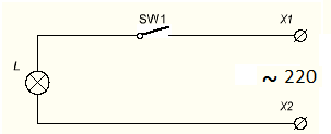
Diagrams do not always read from left to right and top to bottom, it is better to go from a power source. What we can learn from the diagram, look at the right side of it. ~ means AC power supply.
Beside it is written "220" - with a voltage of 220 V. X1 and X2 - it is supposed to be connected to an outlet using a plug. SW1 - this is how the key, toggle switch or button is depicted in the open state. L - conventional image of an incandescent light bulb.
Brief conclusions:
The diagram shows a device that is connected to a 220 V AC network using a plug into an outlet or other detachable connections. It is possible to disable it using a switch or a button. Needed to power the incandescent lamp.
At first glance, it seems obvious, but a specialist should be able to draw such conclusions by looking at the diagram without explanation, this ability will make it possible to diagnose a malfunction and eliminate it, or to assemble devices from scratch.
Let's move on to the next diagram. This is a battery powered flashlight with an emitter installed in it.

Take a look at the diagram, you may see images that are new to yourself. On the right is a power source, this is how a battery or accumulator looks like, a long lead is plus another name - Cathode, a short one - a minus or Anode. At the LED, a plus is connected to the anode (the triangular part of the designation), and a minus is connected to the cathode (on the UGO it looks like a strip).
It must be remembered that for power supplies and consumers, the names of the electrodes are the opposite. Two arrows emanating from the LED let you know that this device emits light, if the arrows, on the contrary, pointed at it, it would be a photodetector. The diodes have the letter designation VDx, where x is a serial number.
Important:
The numbering of parts in the diagrams goes in columns from top to bottom, from left to right.
If you add a built-in stabilization node to the circuit, the voltage of the power supply will be stabilized. In this case, only from an increase in the supply voltage, with drawdowns lower than U stabilization, the voltage will be pulsating in time with drawdowns. VD1 is a zener diode, they are turned on in reverse bias (cathode to a point with a positive potential). They differ in the value of the stabilization current (Istab) and the stabilization voltage (Ustab).

Brief summary:
What can we understand from this diagram? What. It is connected by the primary side (input) to an alternating current network with a voltage of 220 volts. At its output it has two detachable connections - "+" and "-" and a voltage of 12 V, unstabilized.

Let's move on to even more complex circuits and get acquainted with other elements of electrical circuits.
Recently, having learned that I am a radio amateur, two people turned to me for help on the forum of our city, in the Radio branch. Both for different reasons, and both of different ages, are already adults, as it turned out when they met, one was 45 years old, the other 27. Which proves that you can start studying electronics at any age. They were united by one thing, both were somehow familiar with the technique, and would like to master the radio business on their own, but did not know where to start. We continued communication in In contact with, to my answer that there is a lot of information on this topic in the internet, do it - I don't want to, I heard from both about the same - that both do not know where to start. One of the first questions was: what is included in the required minimum knowledge of a radio amateur. It took quite a long time to enumerate the skills they needed, and I decided to write a review on this topic. I think it will be useful to the same beginners as my friends, to everyone who cannot decide where to start their training.
I must say right away that when teaching, you need to evenly combine theory with practice. No matter how much you want, quickly start soldering and assembling specific devices, you need to remember that without the necessary theoretical base in your head, you, at best, will be able to accurately copy other people's devices. Whereas if you know the theory, at least in a minimal amount, you can change the scheme and adjust it to fit your needs. There is such a phrase, I think known to every radio amateur: "There is nothing more practical than a good theory."

First of all, you need to learn how to read schematic diagrams. Without the ability to read circuits, it is impossible to assemble even the simplest electronic device. Also later, it will not be superfluous to master the independent drawing up of schematic diagrams, in a special one.

Soldering parts
It is necessary to be able to identify by appearance, any radio component, and know how it is indicated on the diagram. Of course, in order to assemble, solder any circuit, you need to have a soldering iron, preferably with a power not exceeding 25 watts, and be able to use it well. All semiconductor parts do not like overheating, if you solder, for example, a transistor to a board, and it was not possible to solder the output in 5 - 7 seconds, interrupt for 10 seconds, or solder another part at this time, otherwise there is a high probability of burning the radio part from overheating.

It is also important to solder carefully, especially the closely spaced terminals of radio components, and not hang "snot", accidental short circuits. Always, if in doubt, ring a suspicious place with a multimeter in audible dial mode.

It is equally important to remove the remaining flux from the board, especially if you are soldering a digital circuit, or with a flux containing active additives. You need to wash off with a special liquid, or 97% ethyl alcohol.

Beginners often assemble circuits by surface mounting, right on the pins of the parts. I agree that if the conclusions are securely twisted together, and then they are also soldered, such a device will last a long time. But in this way it is no longer worth assembling devices containing more than 5 - 8 parts. In this case, you need to assemble the device on a printed circuit board. The device assembled on the board is characterized by increased reliability, the connection diagram can be easily tracked along the tracks, and, if necessary, call all connections with a multimeter.

The downside of printed wiring is the difficulty of changing the circuit of the finished device. Therefore, before routing and etching the PCB, you should always first assemble the device on a breadboard. You can make devices on printed circuit boards in different ways, here the main thing is to observe one important rule: the copper foil tracks on the PCB should not have contact with other tracks, where this is not provided for by the scheme.

In general, there are different ways to make a printed circuit board, for example, by separating sections of the foil - tracks, a groove cut by a cutter in foil made from a hacksaw blade. Or by applying a protective pattern that protects the foil underneath (future tracks) from etching with a permanent marker.

Or with the help of LUT technology (laser-ironing technology), where the paths are protected from etching by burning toner. In any case, no matter how we make the printed circuit board, we need to first lay it out in the tracer program. For beginners, I recommend this is a handheld tracer with great features.

Also, with self-wiring of printed circuit boards, or if you printed a finished board, you need to be able to work with documentation for a radio component, with the so-called Datasheets ( Datasheet), pages in PDF format. On the Internet there are Datasheets for almost all imported radio components, with the exception of some Chinese ones.

For domestic radio components, you can find information in scanned reference books, specialized sites that post pages with the characteristics of radio components, and information pages of various online stores such as Chip & Dip... It is imperative to be able to determine the pinout of a radio component, the pinout name is also found, because very many, even two pinout parts, have polarity. Practical skills in working with a multimeter are also required.

A multimeter is a universal device, using only one of it, you can carry out diagnostics, determine the conclusions of the part, their performance, the presence or absence of a short circuit on the board. I think it’s not superfluous, it will remind, especially young novice radio amateurs, about the observance of electrical safety measures when debugging the device.

After assembling the device, it is necessary to arrange it in a beautiful case, so that you will not be ashamed to show it to your friends, which means that you need locksmith skills if the case is made of metal or plastic, or carpentry if the case is made of wood. Sooner or later, any radio amateur comes to the conclusion that he has to deal with minor repairs of equipment, first his own, and then with the acquisition of experience, and according to friends. And this means that it is necessary to be able to diagnose a malfunction, determine the cause of the malfunction, and then eliminate it.

Often, even for experienced radio amateurs, without tools, it is difficult to solder multi-pin parts from the board. Well, if the parts are to be replaced, then we bite off the leads near the case itself, and we solder the legs one by one. It is worse and more difficult when this part is needed to assemble some other device, or when repairs are being made, and the part may need to be soldered back after, for example, when looking for a short circuit on a board. In this case, you need tools for dismantling, and the ability to use them, this is a braid and a desoldering pump.

I do not mention the use of a soldering hair dryer, due to the frequent lack of access to it for beginners.
Output
All of the above is only part of the minimum that a novice radio amateur should know when designing devices, but with these skills, you can already assemble, with the acquisition of little experience, almost any device. Especially for the site - AKV.
Discuss the article WHAT TO START FOR A RADIO AMATEUR
 World News. Barack Obama - biography. Age, personal life, photo Say goodbye to protocol style
 Why dream of baby pacifiers torn
 Don't confuse Luck with Success