What diodes are in the generator g 306. What generators were installed on the MTZ before and what has changed now. Construction machines and equipment, reference book
What if you find that at the rated engine speed, the ammeter displays a discharge current? Check the tension of the alternator belt. If the tension is normal, we are looking for a wire break in the power supply circuit of the field winding. If they are in order, the contacts of the connecting wires are probably acidified.
By the way, with an inter-turn circuit or a break in the turns in the excitation winding, the stator winding is shorted to the case, with a breakdown of diodes of reverse or direct polarity of the rectifier, the same situation arises.
Why can there be a large charging current? It is likely that the battery plates are short-circuited, and this leads to a decrease in the internal resistance of the battery and an increase in current.
Noise and knocks in the generator may occur due to the loosening of the generator drive pulley, the destruction of the bearings or the development of their seats. So the noise is obtained due to the grazing of the rotor on the stator.
How to check the operation of the generator 464.3701 on a tractor? We connect electricity consumers, bring the engine crankshaft speed to the nominal, measure the voltage with a KI-1093 voltammeter between “+” and the unpainted place of the generator case (Fig. 2.2.1) and, gradually adding the load current to 30 A, measure the voltage. It must be at least 12.5 V.
Rice. 2.2.1. Scheme for checking the recoil voltage of the generator under load on the tractor MTZ-80, MTZ-82:
1 - generator; 2 - voltammeter KI-1003
What should I do if the generator voltage is very different from the nominal voltage or if it does not exist at all when the battery is disconnected? The alternator must be removed for inspection and possibly subsequent replacement. How to check the generator MTZ-80, MTZ-82? First you need to check the health of the main elements of the generator using a 12 V test lamp.
The sequence of actions is as follows: remove the rear plastic cover and the integrated device (ID); then we release the leads of the excitation coil and the additional rectifier from the bolts of the terminal panel. We check the absence of a short circuit in the diodes or between the windings and the generator case (see Fig. 2.2.2).

Rice. 2.2.2. Circuits for checking the generator for the absence of a short circuit MTZ-80, MTZ-82
a - how to check the diodes of the rectifier unit; b - how to check the stator windings and reverse polarity diodes; c - how to check straight polarity diodes; d - how to check the diodes of the additional rectifier; e - how to check the excitation windings on the generator housing;
1 - generator housing; 2 - terminal "+"; 3 - terminal "W"; 4 - conclusions of the phases of the rectifier unit; 5 - battery; 6 - terminal "D"; 7 - output terminal of the end of the excitation winding; 8 - output terminal of the beginning of the excitation winding; 9 - control lamp
In the event of a short circuit of the diodes, winding or breakdown to the housing, the control lamp lights up. That is how it should be. In case of violation of the insulation of the windings and malfunctions of the diodes, the generator must be changed. Alignment of the generator is carried out on the control and test benches KI-968 or 532M.
First of all, the voltage of the generator without load is checked. It must be at least 12.5 V at a rotor speed of not more than 1400 rpm. Next, the generator voltage is checked under load, at a load current of 36 A and a rotor speed of 3000 rpm. It must also be at least 12.5 V.
To check the integrated device, the load current is reduced to 5 A, and the rotor speed is tried to be kept within 3000 rpm. In "summer mode" (seasonal adjustment switch in the "L" position), the voltage on the generator should be 13.2-14.1 V. In "winter mode" (seasonal adjustment switch in the "Z" position), the voltage is slightly higher, within 14.3-15.2 V. If these parameters do not match, the integrated device must be changed.
TRACTOR GENERATOR T-130M
The generator serves as a source of electrical energy. Its rated power is 1000 W, the rated voltage is 14 V (Fig. 98).
Generator device. The generator, which is a non-contact five-phase same-pole machine with one-sided electromagnetic excitation with a built-in rectifier and voltage regulator, consists of a rectifier unit 3 (BPV 12-100), stator 5, rotor 24, front 7 and rear 5 covers, excitation coil 23, pulley 10 and impellers 27 for cooling the rectifier.
The stator 6 is a charge, made of sheet steel, has ten teeth, on which coils of a five-phase winding are fixed. The coils are connected in series.
Rotor 24 is a package of a six-beam star, laminated from sheet steel pressed onto the shaft.
A neck and two paws are welded to the front 7 cover, one of which serves to adjust the belt tension, the second to mount the generator. In the front 7 and rear 5 covers of the generator there are ball bearings 22, 25 of a closed design that do not require addition or replacement of lubricant during the entire service life.
Excitation coil 23,
which is a steel sleeve with a flange and winding, located in the front cover. The ends of the winding with lugs are brought out through the stator, the back cover and the rectifier housing and are connected one to the additional output of the generator, the other to the terminal Ш of the voltage regulator.
The rectifier unit 3 (BPV 12-100) consists of a power (main) and additional rectifiers, a voltage regulator unit 1 and a seasonal voltage adjustment switch ("winter - summer"). The power and additional rectifiers are mounted in one housing, and the voltage regulator unit and the seasonal adjustment switch are located on the cover 28 of the rectifier.
The body and plate of the main rectifier are cast from aluminum alloy. The plate is isolated from the body with an insulating gasket and is attached to it with five bolts. The rectifier housing has five holes for the passage of five phase terminals of the stator winding 6 and excitation winding terminals 23. Five diodes of reverse polarity are attached to the rectifier housing, five diodes of direct polarity are attached to the plate. The outputs of the diodes of direct and reverse polarity are connected in pairs by bars with the outputs of the phase windings of the stator.
The additional rectifier consists of three diodes of direct polarity, which are pressed into the bars, connecting in pairs the diodes of direct and reverse polarity of the power rectifier. This rectifier provides automatic protection of the battery against discharge to the excitation winding of the generator when the engine is not running.
Integral Regulator Block 1
voltage is located on the steel cover of the rectifier and consists of a housing molded from glass-filled thermoplastic, an integrated device 35 (IU) with a radiator, a winter-summer seasonal adjustment switch resistor, a filter capacitor 40, a boost resistor 39 to improve self: excitation of the generator.
The integrated device has four outputs C, B, W, D in the form
pads isolated from its base and output M (minus), which is the base of the DUT. The design of the IU is non-separable. The base of the DUT has an orienting tab to prevent it from being installed incorrectly.
Each tractor model has specific design features. Suspension and ignition, systems for starting and introducing fuel into the internal combustion chamber, transmission device - all this determines the specifics of operation and depreciation of tractor mechanisms.
The main electrical equipment that is installed on the tractor is a tractor generator. The generator is necessary to start all the electronic mechanisms of the MTZ tractor. This is the main source of current that drives the ignition system and ensures the operation of electrical appliances and mechanisms.
1 General information
You can find out about a malfunction of the generator by the device on the front panel - an ammeter that measures the amount of current and the condition of the battery. Depending on the current source, the generators for the tractor are:
Variable current sources are quite simple and reliable in operation. To adjust them, it is not necessary to install voltage regulators. But, recharging the battery from an alternating current source is not possible without a rectifier. Therefore, it is more expedient to install a DC device on a tractor with an electric start button.
- engine and transmission;
- power transmission;
- steering and running gear;
- electrical equipment and lubrication;
- hydraulic, pneumatic, fuel and cooling system.
1.1 Description of the generator for MTZ
Basic requirements for generators on MTZ 80, which are part of the tractor's electrical equipment system:
- simple equipment;
- reliable operation;
- compact dimensions;
- opportunity to make repairs yourself.
The generator from the MTZ tractor requires constant attention to the cleanliness of the condition of the mechanisms, the drive belt and the correct wiring. The indicator lamp on the instrument panel signals the control of the generator's serviceability before starting the engine. In different models of tractors, the indicator light differs in intensity.
1.2 Characteristics and diagnostics
The three-phase generator MTZ 80 (G306-D, G - 306A, G - 304A) operates on direct current. This is a tractor generator with one-way electromagnetic excitation. Rotating, the rotor converts mechanical energy into AC electricity using a three-phase rectifier.

The stator, rotor and electromagnetic excitation coil at the end of the front cover are the three main components of the MTZ-80 generator. The rotor looks like a steel hexagonal star attached to the shaft.
You can check the correct operation of the mechanisms yourself using a battery and a 12-volt lamp. Naturally, before that, completely de-energizing the tractor and disconnecting all wires and terminals from the generator itself.
An electromagnetic excitation coil is magnets and cores with windings in series connection. Checking the excitation winding is simple:
- minus fasten to the terminal "M";
- plus on the control terminal III.
A working winding burns half-heartedly (3-3.5 Amperes). If the arrow shows more than 3.5 Amps, this indicates a short circuit between the case and the winding. If the lamp does not light up, then you have a break in the winding. Either it rotted or oxidized.
If the diodes are shorted, the insulation of the heat pipe from the rectifier is broken, or the plus is shorted on the case, then contrary to common sense, the indicator should light up if you connect the minus to the generator and the plus to the indicator lamp to terminal B.
Malfunctions can be caused by contamination and wear of the commutator brush. And a fan failure or bearing problems can cause extraneous noise when the generator is running. The rotor with a loose pulley nut may begin to touch the stator. Problems in the rotor can arise for two reasons: the magnet is cracked or the rotor itself is bent.

If excessive loads are allowed on the generator when all electrical systems are turned on, the generator may overheat. To prevent this from happening, you need to monitor the state of the regulator relay. Its function is to limit the strength of the voltage supplied to the generator to 7 volts. If the voltage is higher or lower, the regulator is not working properly.
One way or another, but having discovered a malfunction of the generator, it must be properly disassembled. All parts with wires must be wiped clean with a rag with gasoline and dried. Rinse all other parts thoroughly in kerosene.
Remember: in no case should you connect the mass regulator to terminals B and W - this can lead to an absolute failure of the entire system.
1.3 How to replace the MTZ generator? (video)
2 Starter malfunctions
If the starter is faulty and periodic clicks are heard, you need to check the voltage supplied to it. And if the rollers of the coupling mechanism (overrunning clutch) are slipping, then when the starter is on, the crankshaft will not rotate.
If the clutch mechanism is poorly adjusted with the traction relay, it may creak or rattle. If the traction relay is working normally, and the armature does not rotate, then the contacts in the relay are burnt.
To check the starter without removing it from the tractor, you need to have the KI1093 device available. If the contacts are oxidized, the battery is faulty or discharged, the values \u200b\u200bof the check will be underestimated.
It is also worth checking the battery clamps for the presence of a white coating of lead oxide, which first reduces, and then stops conducting current. If the starter consumes more current than the prescribed norm, then either the grease in the bearings has thickened, or the armature or starter wiring has shorted. If a fault is found in the starter, it must be replaced.
§ 36. Generator
The generator is used to supply current to electrical appliances when the engine is running at medium and high speeds, as well as to recharge the battery. It converts mechanical energy into electrical energy based on the principle of electromagnetic induction, i.e., the excitation of an electric current in a conductor when it is crossed by magnetic lines of force.
On tractors YuMZ-6L / M and MTZ-50 of new releases, an alternating current generator G-306A (62) is installed. It is a closed contactless three-phase dynamo with built-in rectifier. A characteristic feature of this generator is the absence of brush contacts and rotating windings. Generator power 400 W, rated rectified current 32 A.
The generator consists of a stator 3, a rotor 4 and a rectifier 5. The stator is assembled from electrical steel. It has 9 teeth, on which winding coils are put on 2. Each phase of the winding consists of three coils. In each of the three phases, the coils are connected in series, and the phases are connected in a delta.
Covers are fixed to the stator on both sides. On the insulating block of the rear cover 11, there are clamps 1 of alternating current, to which the ends of the phases of the stator winding are brought out. The terminals of the VL rectifier are connected to the same bolts. On the back cover there are also output terminals M, B.
62. Generator:
1 - AC terminals, 2 - field winding, 3 - stator, 4 - rotor, 5 - rectifier, 6 - generator drive pulley with fan impeller, 7 - diode, 8 - front cover, 9 - field winding coil, 10-pin DC clamp, 11 - back cover
Ш direct current. On the inside of the front cover.V, a coil 9 of the excitation winding is attached, the beginning of the winding is connected to the generator ground, and the end is connected to the terminal Ш.
Rotor 4 of the generator in diameter has the form of a six-beam star, which is made of sheets of electrical steel and is rigidly mounted on the shaft. The latter rotates on two ball bearings that do not require relubrication, a closed design, installed in the covers.
The back cover and the paw attached to it are cast from an aluminum alloy. Two paws are welded to the front steel cover for mounting the generator and adjusting the tension of the drive belt.
Rectifier 5 is fixed on the front cover. It consists of a finned aluminum housing, a heat conductor and six semiconductor diodes of “direct” and “reverse” polarity. The heat conductor is isolated from the body by a thin insulating gasket. Three diodes of "reverse" polarity are mounted in the case, and diodes of "straight" polarity are mounted in the heat conductor. The outputs of the diodes are connected in pairs with the phases of the generator. A rubber sealing ring is installed between the rectifier housing and the generator cover, which prevents dust and dirt from entering the rectifier.
For better cooling, the body of the rectifier is finned. The rectifier is assembled in three
phase bridge circuit. The positive pole of the rectifier is connected to terminal B on the alternator rear cover block with a flexible wire.
The generator is driven by a belt through a pulley b, fixed on the shaft with a key and a nut. A fan is attached to the pulley on the generator side, which serves to cool the generator and rectifier.
The principle of operation of the generator is known from physics. When the rotor rotates, the magnetic field of the excitation system crosses the three-phase stator winding and induces an electromotive force (emf) variable in magnitude and direction in it. Under the influence of e. d.s. an alternating current appears in the circuit, which is converted by the rectifier into direct current and supplied to consumers.
Normal operation of the generator is possible subject to compliance with the operating rules.
The generator must not be washed with fuel or high pressure water jets. To excite the generator, it is necessary to turn on the "mass" switch, otherwise it will not generate electricity. If, after starting the engine, turn off the "mass", then with a working generator, the control lamp "Turning on the mass" continues to burn. When the engine is stopped, the "mass" is turned off to prevent the battery from being discharged through the excitation winding of the generator.
63. Relay-regulator:
a - device, b - inclusion in the circuit; / - voltage regulator, 2 - protection relay, 3 - cover, 4 - transistor, 5 - case, 6 - seasonal voltage adjustment screw, 7 - mass switch; G - generator, R - relay-regulator, 6 - battery, M - ground, W - clamp connected to the excitation winding of the regulator (shunt), 6 - clamp connected to the rectifier clamp

The generator of the described type works in a set with a contact-transistor relay-regulator PP-362B (63). The relay-regulator is installed under the instrument panel and includes two elements: a voltage regulator / and a protection relay 2.
The voltage regulator maintains the generator voltage within 13.0-14.2 V. It consists of a transistor 4 and a vibration relay that controls the transistor included in the generator excitation winding circuit.
Protection relay 2 serves to protect the transistor from short circuit currents of the excitation winding circuit to ground.
There are three clamps on the relay-regulator panel: M - for connecting the "mass" of the generator, Ш - for connecting the excitation winding of the generator, B- for connecting the rectifier, load and battery. On the outside of the relay-regulator there is a PPR device (seasonal voltage adjustment switch), which allows seasonally adjusting the voltage difference within 0.8-1.0 V. Opening and adjusting the relay-regulator can only be done by a foreman in a workshop that has the necessary measuring instruments . Even a short-term connection (test "for a spark") of the terminals Ш and В of the generator and the relay-regulator with "ground" is prohibited.
The G-304A generator, previously installed on the tractors under study, does not differ from the G-306A generator in terms of the principle of operation.
however, their circuitry, construction, and materials are not the same. The G-306A generator is more powerful than the G-304A generator, has a smaller weight and overall dimensions. It is one-sided excitation, and the G-304A is two-sided, since it has two excitation winding coils, each placed in one of the covers and connected in parallel. Both generators are paired with a relay-regulator RR-362B.
A car generator is the most affordable generator, and if you plan to make a wind generator, then it is the car generator that immediately involuntarily comes to mind when looking for a generator. But without alteration to magnets and rewinding the stator, it is not suitable for a windmill, as the operating speed of car generators is 1200-6000 rpm.
Therefore, in order to get rid of the excitation coil, the rotor is converted to neodymium magnets, and in order to raise the voltage, the stator is rewound with a thinner wire. The result is a generator with a power of 150-300 watts at 10 m / s without using a multiplier (reducer). The screw is placed on such a converted generator with a diameter of 1.2-1.8 meters.
The car generator itself is very affordable and you can easily buy it used or new in the store, they are not expensive. But to remake the generator, you need neodymium magnets, a wire for rewinding, and this is still an additional waste of money. So, of course, you need to be able to do this, otherwise you can ruin everything and throw it in the trash. Without alteration, the generator can be used if you make a multiplier, for example, if you make the gear ratio 1:10, then at 120 rpm, the 12 volt battery will start charging. In this case, the excitation coil (rotor) will consume about 30-40 watts, and all that remains will go to the battery.
But if you do it with a multiplier, then of course you get a powerful and large wind generator, but with a small wind, the excitation coil will consume its 30-40 watts and the battery will get little. Normal operation will probably be in wind from 5 m/s. In this case, the screw for such a windmill should be about 3 meters in diameter. The result is a complex and heavy structure. And the most difficult thing is to find a ready-made multiplier, suitable with minimal alterations, or making a homemade one. It seems to me that making a multiplier is more difficult and more expensive than converting a generator to magnets and rewinding a stator.
If the auto-generator is used without alteration, then it will start charging the 12 volt battery at 1200 rpm. I myself did not check at what speed charging starts, but after a long search on the Internet I found some information that indicates that at 1200 rpm the battery starts charging. There are mentions that the generator charges at 700-800 rpm, but it is not possible to verify this. I determined from the photographs of the stator that the stator winding of modern VAZ generators consists of 18 coils, and each coil has 5 turns. I calculated what voltage should turn out according to the formula from this article Calculation of the generator. As a result, I just happened to have 14 volts at 1200 rpm. Of course, the generators are not all the same and I read somewhere about 7 turns in the coils instead of five, but basically 5 turns in the coil, which means that 14 volts is still achieved at 1200 rpm, we will proceed from this further.
Two-bladed propeller on the generator without alteration
In principle, if you put a high-speed two-bladed propeller with a diameter of 1-1.2 meters on the generator, then such revolutions are easily achieved with a wind of 7-8 m / s. This means that you can make a windmill without altering the generator, only it will work in wind from 7m / s. Below is a screenshot with the data of a two-blade propeller. As you can see, the speed of such a propeller with a wind of 8 m / s is 1339 rpm.
 >
>
Since the propeller speed grows linearly depending on the wind speed, then (1339: 8 * 7 = 1171 rpm) at 7 m / s the battery will start charging. At 8 m/s, the expected power, again, according to the calculation, should be (14:1200*1339=15.6 volts) (15.6-13=2.6:0.4=6.5 amps*13=84.5 watts). The useful power of the screw, judging by the screenshot, is 100 watts, so it will freely pull the generator and should give out even more revolutions than indicated when underloaded. As a result, 84.5 watts should be from the generator at 8 m / s, but the excitation coil consumes about 30-40 watts, which means that only 40-50 watts of energy will go to the battery. Very little, of course, since a generator converted to magnets and rewound at the same wind at 500-600 rpm will give out three times more power.
With a wind of 10 m / s, the revolutions will be (1339: 8 * 10 = 1673 rpm), the voltage at idle will be (14: 1200 * 1673 = 19.5 volts), and under load, the battery will be (19.5-13 = 6.5: 0.4 = 16.2 amperes *13=210 watts). The result is 210 watts of power minus 40 watts per coil, leaving 170 watts of usable power. At 12 m / s it will be something like this 2008 rpm, no-load voltage 23.4 volts, current 26 amps, minus 3 amps for excitation, and that 23 amps battery charging current, power 300 watts.
If you make a screw of a smaller diameter, then the speed will increase even more, but then the screw will not pull the generator when it reaches the battery charging threshold. I counted different options while writing this article and the two-blade propeller turned out to be the most optimal for the generator without alteration.
In principle, if you count on winds from 7 m/s and above, then such a wind generator will work well and produce 300 watts at 12 m/s.
At the same time, the cost of the windmill will be quite small, in fact, only the price of the generator, and the screw and the rest can be made from what is. Only the screw must be done according to the calculations.
A correctly altered generator begins to charge already from 4 m / s, at 5 m / s the charging current is already 2 amperes, while since the rotor is on magnets, all the current goes to the battery. At 7 m / s, the charging current is 4-5 amperes, and at 10 m / s it is already 8-10 amperes. It turns out that only with a strong wind of 10-12 m/s, the generator without alteration can be compared with the altered one, but it will not give anything in a wind less than 8 m/s.
Self-excited car generator
In order for the generator to self-excite without a battery, you need to put a couple of small magnets in the rotor. If the excitation coil is powered from a battery, then it constantly and regardless of whether the wind generator produces energy or not, will consume its 3 amperes and charge the battery. To prevent this from happening, you need to put a blocking diode so that the current only goes to the battery, but does not go back.
The excitation coil can be powered from the generator itself, minus from the housing, and plus from the positive bolt. And in the teeth of the rotor you need to put a couple of small magnets for self-excitation. To do this, you can drill holes with a drill and put small neodymium magnets on the glue. If there are no neodymium magnets, then you can insert ordinary ferrite ones from the speakers, if they are small, then drill it and insert it, or lay it between the claws and fill it with epoxy.
You can also use the so-called tablet, that is, a relay-regulator like in a car, which will turn off the excitation if the battery voltage reaches 14.2 volts, so as not to overcharge.
Below in the figure is a self-excitation generator circuit. In general, the generator itself is excited as the rotor has residual magnetization, but this happens at high speeds, it is better to add magnets for reliability. A relay-regulator is included in the circuit, but it can be excluded. A decoupling diode is needed so that the battery does not discharge as without a diode, current will flow into the excitation winding (rotor).
 >
>
Since the wind generator will be very small with a propeller with a diameter of only 1 meter, no protection against strong winds is needed and nothing will happen to it if there is a strong mast and a strong propeller.
There are generators for 28 volts, but if they are used to charge a 12 volt battery, then the revolutions need to be half as much, about 600 rpm. But since the voltage will not be 28 volts, but 14, then the excitation coil will give only half the power and the generator voltage will be less, so nothing will come of it. Of course, you can try in a generator whose stator is wound on 28 volts, put the rotor on 12 volts, then it should be better and charging will start earlier, but then you need two identical generators to replace the rotor, or look for a separate rotor or stator.
§ 35. Battery
§ 36. Generator
§ 37. Starter
§ 38. Lighting and signaling devices
§ 39. Magneto and glow plug
§ 40 Maintenance of electrical equipment
§ 36. Generator
The generator is used to supply current to electrical appliances when the engine is running at medium and high speeds, as well as to recharge the battery.
It converts mechanical energy into electrical energy based on the principle of electromagnetic induction, i.e., the excitation of an electric current in a conductor when it is crossed by magnetic lines of force.
On tractors YuMZ-6L / M and MTZ-50 of new releases, an alternating current generator G-306A (62) is installed. It is a closed contactless three-phase dynamo with built-in rectifier. A characteristic feature of this generator is the absence of brush contacts and rotating windings. Generator power 400 W, rated rectified current 32 A.
The generator consists of a stator 3, a rotor 4 and a rectifier 5. The stator is assembled from electrical steel. It has 9 teeth, on which winding coils are put on 2. Each phase of the winding consists of three coils. In each of the three phases, the coils are connected in series, and the phases are connected in a delta.
Covers are fixed to the stator on both sides. On the insulating block of the rear cover 11, there are clamps 1 of alternating current, to which the ends of the phases of the stator winding are brought out. The terminals of the VL rectifier are connected to the same bolts. On the back cover there are also output terminals M, B.

62. Generator:
1 - AC terminals, 2 - field winding, 3 - stator, 4 - rotor, 5 - rectifier, 6 - generator drive pulley with fan impeller, 7 - diode, 8 - front cover, 9 - field winding coil, 10-pin DC clamp, 11 - back cover
Ш direct current. On the inside of the front cover.V, a coil 9 of the excitation winding is attached, the beginning of the winding is connected to the generator ground, and the end is connected to the terminal Ш.
Rotor 4 of the generator in diameter has the form of a six-beam star, which is made of sheets of electrical steel and is rigidly mounted on the shaft. The latter rotates on two ball bearings that do not require relubrication, a closed design, installed in the covers.
The back cover and the paw attached to it are cast from an aluminum alloy. Two paws are welded to the front steel cover for mounting the generator and adjusting the tension of the drive belt.
Rectifier 5 is fixed on the front cover. It consists of a finned aluminum housing, a heat conductor and six semiconductor diodes of “direct” and “reverse” polarity. The heat conductor is isolated from the body by a thin insulating gasket. Three diodes of "reverse" polarity are mounted in the case, and diodes of "straight" polarity are mounted in the heat conductor. The outputs of the diodes are connected in pairs with the phases of the generator. A rubber sealing ring is installed between the rectifier housing and the generator cover, which prevents dust and dirt from entering the rectifier.
For better cooling, the body of the rectifier is finned. The rectifier is assembled in three
phase bridge circuit.
The positive pole of the rectifier is connected to terminal B on the alternator rear cover block with a flexible wire.
The generator is driven by a belt through a pulley b, fixed on the shaft with a key and a nut. A fan is attached to the pulley on the generator side, which serves to cool the generator and rectifier.
The principle of operation of the generator is known from physics. When the rotor rotates, the magnetic field of the excitation system crosses the three-phase stator winding and induces an electromotive force (emf) variable in magnitude and direction in it. Under the influence of e. d.s. an alternating current appears in the circuit, which is converted by the rectifier into direct current and supplied to consumers.
Normal operation of the generator is possible subject to compliance with the operating rules.
The generator must not be washed with fuel or high pressure water jets. To excite the generator, it is necessary to turn on the "mass" switch, otherwise it will not generate electricity. If, after starting the engine, turn off the "mass", then with a working generator, the control lamp "Turning on the mass" continues to burn. When the engine is stopped, the "mass" is turned off to prevent the battery from being discharged through the excitation winding of the generator.
63. Relay-regulator:
a - device, b - inclusion in the circuit; / - voltage regulator, 2 - protection relay, 3 - cover, 4 - transistor, 5 - case, 6 - seasonal voltage adjustment screw, 7 - mass switch; G - generator, R - relay-regulator, 6 - battery, M - ground, W - clamp connected to the excitation winding of the regulator (shunt), 6 - clamp connected to the rectifier clamp

The generator of the described type works in a set with a contact-transistor relay-regulator PP-362B (63). The relay-regulator is installed under the instrument panel and includes two elements: a voltage regulator / and a protection relay 2.
The voltage regulator maintains the generator voltage within 13.0-14.2 V. It consists of a transistor 4 and a vibration relay that controls the transistor included in the generator excitation winding circuit.
Protection relay 2 serves to protect the transistor from short circuit currents of the excitation winding circuit to ground.
There are three clamps on the relay-regulator panel: M - for connecting the "mass" of the generator, Ш - for connecting the excitation winding of the generator, B- for connecting the rectifier, load and battery. On the outside of the relay-regulator there is a PPR device (seasonal voltage adjustment switch), which allows seasonally adjusting the voltage difference within 0.8-1.0 V. Opening and adjusting the relay-regulator can only be done by a foreman in a workshop that has the necessary measuring instruments . Even a short-term connection (test "for a spark") of the terminals Ш and В of the generator and the relay-regulator with "ground" is prohibited.
The G-304A generator, previously installed on the tractors under study, does not differ from the G-306A generator in terms of the principle of operation.
however, their circuitry, construction, and materials are not the same.
The G-306A generator is more powerful than the G-304A generator, has a smaller weight and overall dimensions. It is one-sided excitation, and the G-304A is two-sided, since it has two excitation winding coils, each placed in one of the covers and connected in parallel. Both generators are paired with a relay-regulator RR-362B.
Stroy-Tekhnika.ru
Construction machines and equipment, reference book
TO Category:
Tractors MTZ-100 and MTZ-102
Unified tractor generator 46.3701
General information. Generator 46.3701 is designed for tractors and self-propelled agricultural machines. Its power is 0.7 kW, and it is made with a built-in voltage regulator.
The presence of a powerful power source on the tractor makes it possible to solve a number of problems to improve the working conditions of the tractor driver and increase labor productivity ei.
Generator 46.3701 has several modifications that differ in the size of the drive pulley. So, for example, the modification generator 54.3701 is installed instead of the G306 generator.
On a unified generator, in addition to the main rectifier, there is an additional one (terminal D), with which the battery is prevented from discharging to the excitation winding of the generator during stops, and a starter blocking relay is also connected.
Generator 46.3701 has reliable self-excitation due to the use of permanent magnets. The loss of residual magnetization is excluded. Self-excitation is provided with a connected rated load, which makes it possible to carry out agricultural work even in the absence of a battery on the tractor.
A decrease in specific metal consumption or an increase in specific power by a factor of 1.75 was obtained as a result of the use of circulating cooling similar to automobile generators. From the ingress of large particles, the internal cavity of the generator is protected by a plastic mesh cover on the air intake side. The cover is easily removable, and it must be removed periodically (once a season) to remove particles accumulated under it.
Efficient cooling of bearing units significantly increases the life of the generator.
The generator device is shown in Figure 1. It is a single-pole three-phase inductor machine.
The rotor consists of a shaft with a six-beam asterisk made of sheet steel, a magnetic core bushing, a pulley and a centrifugal fan located on it. Magnets are cast in a special aluminum frame with six beak-shaped protrusions placed between the teeth of the rotor packs.
The stator is a package with nine teeth, on which coils are located (three per phase). The cover on the drive side is steel with a welded flange on the fan side. The flange has mounting and tension paws. This cover contains a sleeve-ka-magnetic circuit with an excitation winding. A rectifier unit with three additional diodes is installed in the aluminum cover on the side opposite to the drive. A plastic mesh cover with holes for electrical outlets covers the end of the aluminum cover.

Rice. 1. Generator 46.3701:
1- back cover; 2 - poropa sleeve; 3 - cover of the regulating device; 4 - bearing; 5 - block; 6 - coupling bolt; 7 - rotor; 8 - stator; 9 - excitation coil, 10 - fan; 11 - bearing cap; 12 - pulley; 13 - bearing; 14 - front cover.
Both bearing caps have openings for intake and exhaust of cooling air. Bearing 6-180603 is installed in the cover on the drive side, and bearing 6-180502 is installed on the opposite side. In the cavity between the aluminum and plastic covers there is an integral regulator block.
The alternator is held together with three bolts. Unlike the generator 13.3701 (G306), all electrical connections are inside. Figure 110 shows the electrical connection diagram of the 46.3701 generator; it practically does not differ from the 13.3701 generator circuit.
Generator installation. The connecting dimension between the paws is 90 ± 0.4 mm, which allows, if necessary, to install the generator instead of the generator 13.3701. Other overall and connecting dimensions are the same as for 13.3701 and G306. Generator 46:3701, when delivered as spare parts, has a foot spacing of 130 mm. The paws of the rear cover of the generator are fixed with a bolt of greater length with the installation of nuts or a special split sleeve in the hole of the rear paw, which can be mixed in the axial direction.
Figure 3 shows the options for mounting the generator on brackets 90 and 130 mm in size.
The generator is not installed on the cast bracket of the D-245 diesel engine,
since the side wall of the bracket prevents the generator from turning when putting on the belt. You need to either modify the bracket or replace it with a bracket of a different size.
When servicing the generator, it is necessary to monitor the reliability of all fasteners, the tension of the drive belt, its general serviceability and cleanliness. Dust and dirt are removed with a brush or a damp cloth.
The serviceability of the generator is checked before starting work using a warning lamp installed on the instrument panel. If the generator is in good condition, the lamp lights up when the "ground" switch is closed before starting the diesel engine. After starting, the control lamp goes out. Having stopped the diesel engine, it is necessary to open the “mass” switch (the control lamp goes out).
On the tractor, the serviceability of the generator is checked only when the diesel engine is not running, by disconnecting the wires from all generator terminals.
The test is carried out using a 12 V lamp and a battery.
When checking the excitation winding, the negative terminal of the battery is connected to the generator terminal M, its positive terminal is connected through a test lamp to the generator terminal Ш.
If the excitation winding is working, then the lamp burns half-heartedly (current strength 3.0 ... 3.5 A). The full glow of the lamp (current strength more than 3.5 A) indicates a short circuit between the excitation winding and the generator housing. If the lamp does not light, there is a break in the excitation winding.
The serviceability of the rectifier and stator windings is checked in the following order.

Rice. 2. Electric circuit of the generator 46.3701.

3. Generator installation diagrams. 54.3701:
1 - generator; 2 - adjusting washers; 3 - bolt M10 X 55; 4 - bracket; 5 - bolt; 6 - nut No. 110.
1. The negative terminal of the battery is connected to the M terminal of the generator, and its positive terminal is connected through a test lamp with terminal B. In this case, the lamp should not light. If the lamp is on, this indicates the following rectifier malfunctions: short circuit in one or more diodes of both polarities; insulation breakdown between the heat sink and the rectifier case; shorting the positive terminal to the generator case.
2. The negative terminal of the battery is connected to one of the alternating current terminals of the generator, and its positive terminal is connected through a test lamp to terminal B of the generator. In this case, the lamp should not burn. Otherwise, one or more straight polarity diodes are broken.
3. The positive terminal of the battery is connected through a test lamp to one of the alternating current terminals of the generator, and its negative terminal is connected to the M terminal of the generator. The lamp also should not burn. If the lamp lights up, it means that one or more diodes of reverse polarity are broken or a short circuit of the stator winding to the generator housing has occurred.
TO category: — MTZ-100 and MTZ-102 tractors
Home → Directory → Articles → Forum
Malfunctions and repair of the MTZ tractor generator
What if you find that at the rated engine speed, the ammeter displays a discharge current? Check the tension of the alternator belt. If the tension is normal, we are looking for a wire break in the power supply circuit of the field winding. If they are in order, the contacts of the connecting wires are probably acidified.
By the way, with an inter-turn circuit or a break in the turns in the excitation winding, the stator winding is shorted to the case, with a breakdown of diodes of reverse or direct polarity of the rectifier, the same situation arises.
Why can there be a large charging current? It is likely that the battery plates are short-circuited, and this leads to a decrease in the internal resistance of the battery and an increase in current.
Noise and knocks in the generator may occur due to the loosening of the generator drive pulley, the destruction of the bearings or the development of their seats. So the noise is obtained due to the grazing of the rotor on the stator.
How to check the operation of the generator 464.3701 on a tractor? We connect consumers of electricity, we bring the engine crankshaft speed to the nominal one, we measure it with a KI-1093 voltammeter between “+” and an unpainted place in the generator housing (Fig.
2.2.1) and, gradually adding the load current up to 30 A, we measure the voltage. It must be at least 12.5 V.

Rice. 2.2.1. Scheme for checking the recoil voltage of the generator under load on the tractor MTZ-80, MTZ-82:
1 - generator; 2 - voltammeter KI-1003
What should I do if the generator voltage is very different from the nominal voltage or if it does not exist at all when the battery is disconnected? The alternator must be removed for inspection and possibly subsequent replacement. How to check the generator MTZ-80, MTZ-82? First you need to check the health of the main elements of the generator using a 12 V test lamp.
The sequence of actions is as follows: remove the rear plastic cover and the integrated device (ID); then we release the leads of the excitation coil and the additional rectifier from the bolts of the terminal panel. We check the absence of a short circuit in the diodes or between the windings and the generator case (see Fig. 2.2.2).

Rice. 2.2.2. Circuits for checking the generator for the absence of a short circuit MTZ-80, MTZ-82
a - how to check the diodes of the rectifier unit; b - how to check the stator windings and reverse polarity diodes; c - how to check straight polarity diodes; d - how to check the diodes of the additional rectifier; e - how to check the excitation windings on the generator housing;
1 - generator housing; 2 - terminal "+"; 3 - terminal "W"; 4 - conclusions of the phases of the rectifier unit; 5 - battery; 6 - terminal "D"; 7 - output terminal of the end of the excitation winding; 8 - output terminal of the beginning of the excitation winding; 9 - control lamp
In the event of a short circuit of the diodes, winding or breakdown to the housing, the control lamp lights up. That is how it should be. In case of violation of the insulation of the windings and malfunctions of the diodes, the generator must be changed. Alignment of the generator is carried out on the control and test benches KI-968 or 532M.
First of all, the voltage of the generator without load is checked. It must be at least 12.5 V at a rotor speed of not more than 1400 rpm. Next, the generator voltage is checked under load, at a load current of 36 A and a rotor speed of 3000 rpm. It must also be at least 12.5 V.
To check the integrated device, the load current is reduced to 5 A, and the rotor speed is tried to be kept within 3000 rpm. In "summer mode" (seasonal adjustment switch in the "L" position), the voltage on the generator should be 13.2-14.1 V. In "winter mode" (seasonal adjustment switch in the "Z" position), the voltage is slightly higher, within 14.3-15.2 V. If these parameters do not match, the integrated device must be changed.
 How to store porcini mushrooms after harvest and for the winter
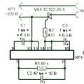 Speed regulator for grinder - to make the machine more reliable and functional
 choice of strategic alternatives