How to make a combination lock yourself. Wooden combination lock Do-it-yourself mechanical combination lock diagram
Combination locks have a number of advantages over key operated locks. Among them are the absence of a keyhole into which hooligans can stuff various garbage, the reliability of the mechanism, the absence of the need to carry a key with you, risking losing it, and many others.
However, when thinking about buying and installing such a lock, many are faced with the problem of the high cost of such locking devices. This prompts good owners "with straight hands" to think about how you can make a combination lock with your own hands. Within the framework of this article, we will consider the possibilities of manufacturing such locks, their differences from factory serial samples, and also study the examples of creating a mechanical and electronic locking device offered by experts.
Is it possible to make an electronic or mechanical combination lock?
Theoretically, having a desire, some experience with electricity and semiconductor microcircuits, as well as with locking mechanisms, you can make an electronic or mechanical combination lock. On the Internet, you can find many articles and notes that provide diagrams of electronic and mechanical combination locks. However, you need to understand that their quality and reliability will be a big question.
Faced with the problems of self-manufacturing electronic combination locks, we are forced to state that most of the schemes proposed in the articles are not operational. As for mechanical locks, some of the proposed options are too complicated to manufacture, while others require factory components, which, however, is not a problem in all cases.
Having studied the topic thoroughly, we came to the conclusion that it is possible to make an electronic or mechanical combination lock on our own. However, if you initially place increased demands on it in terms of performance, then it’s better not to waste time and effort, buy a factory locking device. It is possible that its cost will eventually pay off the time spent on fruitless searches for a suitable circuit and the efforts to re-solder electrical circuits and remake the mechanical elements of the lock. In addition, home-made locking devices have significant differences from factory samples, which we will talk about later.
How will homemade combination locks differ from factory ones?
 As mentioned above, do-it-yourself combination locks are different from those that can be bought in a store. There are many reasons for this, including the use of artisanal techniques when creating individual elements and the skill of a person who took up the manufacture of a locking device, and most importantly, the approach that he chose before starting work.
By the way, there are two main approaches in the manufacture of homemade locking devices. The first (and in our opinion the most correct one) involves the use of factory parts in the manufacture of an electronic or mechanical lock, so to speak, "in the author's layout." And the second approach, more risky, involves the handicraft production of individual parts of the locking device and the use of improvised means in work, so how will home-made locks differ from those that you can buy in a store?
- A homemade combination lock looks aesthetically less attractive than a factory model, although there are exceptions to this rule.
- No one can guarantee the long and stable operation of a homemade device. It is possible that at one "perfect" moment it will stop working, giving you a lot of trouble.
- Code locking devices, assembled according to some schemes from the Internet, are extremely unreliable. They are easy to open by selecting numbers, or even more so by simultaneously clicking on all the numbers, which does not stand up to criticism.
- Factory models of combination locks suggest a simple and intuitive installation. Homemade samples of locking devices are more difficult to install. Sometimes you have to spend a lot of time before you can figure out how to carry out its correct installation.
- And, finally, it should be noted that the cost of a factory combination lock includes its installation. The master will come to you and qualitatively install the device without your participation, which will certainly save your time and effort.
We select the tool and suitable parts
The process of self-manufacturing an electronic or mechanical combination lock is preceded by the selection of suitable parts and tools. In this case, there is no universal set of tools and parts, since their selection will depend on many factors. However, it is quite possible to say exactly what tools and materials you will need. So, for the manufacture of an electronic or mechanical combination lock, the following parts and tools will be required:
- ready-made factory microcircuits or parts for their manufacture (board, wires, radio components);
- soldering iron, tin, rosin;
- mechanical parts of the lock (levers, bolt, springs);
- lock body and fasteners;
- drill, grinder, screwdriver;
- glue, material for making buttons, etc.
An example of the manufacture of an electronic combination lock
 In our opinion, the most successful microcircuit for a home-made electronic combination lock is 561L0A7. You can see its topology, along with the rest of the castle elements, before your eyes. This scheme has a number of advantages over other samples:
- low power consumption;
- the ability to work immediately from two power sources, a 12-volt battery and the mains;
- high reliability against tampering, both intellectual and brute.
Low power consumption is ensured by the fact that the entire electrical circuit is de-energized at rest, and in order to connect the power, you need to press a special button, for example, it will be "0". After pressing the "0" button, you have 15-20 seconds to dial the code and open the lock, after which the circuit is de-energized again. By the way, in this scheme, the SA 1 code panel is used, which is displayed outside. To set the code, the SR 1 panel is used, connected to a device for fixing frequencies taken from the radio receiver. It is enough to arrange the plugs in the sockets of the device in a special way, which will correspond to a 4-digit code.
The scheme protects the castle from intellectual hacking by selection. In the case of the code set time will be invalid button is pressed, set the panel is locked for 15 seconds, then the set can be repeated. You can increase the time lock with the wrong set of each code. So, let's briefly review the procedure for manufacturing an electronic combination lock. 
- Acquire or soldered above the chip.
- Take the plastic box measuring 15 × 15 cm, a slotted hole in it and assemble it on the bar code, not forgetting to bring the wire.
- Inside boxes set chip and connect it to the code panel.
- Set on top of the frequency locking apparatus from the radio and connect it to the IC using wires.
- A slotted hole in the box so as to gain access to frequencies fixation device. We manufacture of a piece of rubber plug, so as to make the device more aesthetically pleasing appearance.
- The resulting control unit locking mechanism connect to the battery, and that, in turn, through the power supply to the mains.
- Using wires connect the control unit to unlock the door drive, which is used in vehicles with a central lock. And we have, in turn, connect to a conventional latch which is mounted on the mechanical locks. You can do without a drive unlock the door and instead connect the control unit with electric. Coded electronic lock ready.
EXAMPLE manufacture mechanical combination lock
 Mechanical combination lock consists of several plates (moving and stationary), washers, rivets, bolt guides, bolts, handles for opening the door, springs, stops and pins. Lock device shown. To open the lock you want to place the finger knob so that the movable plate slipped the bolt and open the lock. Several such handles all prevent the bolt, unless of course they do not rotate properly. Mechanical combination lock is made in the following order.
- Take the three narrow rectangular metal plates, in this case, large values of the size and thickness of the metal does not have important basic principle. Folding plate stack and four drill holes of 10 mm diameter each.
- Under each hole is necessary to pick up the bolts so that they are easy to enter there, but not dangling freely, their heads have to grind so they resemble rivets.
- rod bolt with a file to be processed so as to form two planes.
- Cuts must be made in the movable bar, this will ensure the mobility of the handle.
- To open the lock from the inside, you need to install a special handle for the deadbolt.
- You need to make marks on the bolt heads in order to make it more convenient to type the code.
- We select a case that is suitable in size and begin to assemble the lock mechanism.
- We assemble the plates in the sequence shown in the figure, inserting the button bolts into the holes. They will need to be brought out by drilling the appropriate holes in the door leaf.
- Movable plates must be spring-loaded to the handle.
- We mount the box with the mechanism on the door using suitable fasteners and check the performance of the mechanical combination lock.
Summing up, we note that answering the question of how to make a combination lock is far from simple. There are many options and schemes for the manufacture of such a locking device. And even if you take a workable scheme, this does not mean that you will succeed, because a lot depends on your quick wits, efficiency and experience in manufacturing and installing locks. Therefore, if you feel that this work is not up to you, it is better to purchase a good factory lock, in which case the likelihood that it will not let you down is much higher. Good luck with your experiments.
Hello everyone, in this article I will show you how to make a simple but reliable combination lock without using a complex and expensive microcontroller.
Combination lock scheme
The basis of our circuit is a pulse counter - a CD4017 microcircuit. The domestic analogue of this microcircuit is K561IE8, and we use buttons as an input pulse generator.

One push of a button. In this case, only four buttons are correct or working, there can be as many non-functioning buttons as you like. In this scheme, the working buttons are from S1 to S4, and the false ones are from S5 to S12. When power is applied to the circuit, a logical unit appears on the third output of the microcircuit.

When you press the S1 button, the logical unit enters the fourteenth input of the microcircuit and the counter starts counting pulses.

After that, the logical unit appears already on the second output of the microcircuit.

When you press the S2 button, a logical unit goes to input fourteen and now pin four opens, after that pin seven opens exactly like this and, at the very end, the tenth pin of the microcircuit, which in turn opens the transistor, and instead of the LED, you can connect to the output of the transistor relay and then control network devices.

The buttons from S1 to S4 must be pressed in a certain sequence. This microcircuit has a reset function and if you press one of the non-working buttons, then the logical unit will go to pin fifteen Reset, and then the logical unit will again go to the third output and the code will need to be re-entered.

Once the theory is out of the way, let's move on to practice. I assembled the circuit on a breadboard 3 by 7 cm, after assembly, you need to check the circuit for operability - for this, we solder a wire about 5-7 cm long to the fourteenth output and first check the correct combination, and then the reset function. As a keyboard, it is convenient to use tact buttons (such as touch buttons, as in imported radio equipment). The supply voltage of our circuit is 12 volts, and the standby current is 3 mA. As a result, we get a reliable, easy to manufacture, and most importantly - a cheap combination lock. Take PCB files
Conventional mechanical locks have a low degree of protection due to the limited number of combinations. It is also possible to lose the key or remove a cast from it. Electronic combination locks provide individual or collective access to premises, equipment, safes and other objects without the use of traditional mechanical locks and keys.
In electronic combination locks, as in mechanical ones, the principle of coincidence of signs is often used. It is obvious that the simplest and, accordingly, the most reliable coincidence scheme is the user-defined switching sequence of switching elements.
On fig. 22.1 shows one of the simplest combination lock schemes using an electromagnetic locking device [RL 9/99-24]. The power supply circuit of the electromagnetic lock and its design are not given. To turn on the executing device (electromagnetic lock), relay K1 is intended, and relay K2 turns on the bell, the specific circuit of which is also not given. Buttons of the typesetting field SB1 - SBn, as well as the SB0 "Call" button are installed on the front door.
SBm buttons are installed indoors in different places, which allows the owner to open the door without coming up to it. Buttons SB1 - SB4 are active for dialing a code combination. Their number can be increased or decreased at the discretion of the user.
The device works as follows: when power is applied, capacitors C1 and C2 are charged in 10 seconds, and the electronic lock is ready for operation. Relay K1 is activated for the duration of the discharge of the capacitor C1 through the winding (for 2 ... 3 seconds) only when the buttons SB1 - SB4 are pressed simultaneously, and, accordingly, does not respond to their successive pressing in turn. If any of the buttons SB5 - SBn is pressed by mistake, the capacitor C1 will be instantly discharged through the resistor R2, and the device will come into operation only after 10 seconds (after the capacitor C1 is charged). At this time, even the correct set of the code will not be able to open the lock.
The power circuit of the relay K2 of the bell circuit also uses a timing circuit - R3, C2. This eliminates frequent signaling (more often than after 10 seconds and lasting more than 2 ... 3 seconds), which does not create unnecessary noise and does not allow you to burn out the bell winding.
The bell button SB0 is connected through the diode VD1 and the resistor R2 to the capacitor C1 of the combination lock. When trying to enter a room, intruders often check for the presence of owners in it - they press the bell button, and then try to open the door. Pressing the bell button SB0 leads to the discharge of the capacitor C1, which makes it impossible to open the lock for the delay time even if the correct combination is dialed.
On fig. 22.2 shows a diagram of a combination lock using a different method of protection: the lock only works when the buttons SB1 - SB4 and the SB0 "Call" button are pressed simultaneously [RL 9 / 99-24]. If the SB0 button is pressed before the SB1 - SB4 buttons are pressed simultaneously, the bell is turned on, which allows you to attract the attention of the owners (if they are at home) or third parties.
As in the previous case, pressing any of the buttons SB5 - SBm will cause the discharge of the time-setting capacitor C1. Resetting will be possible only after 10 seconds, when the voltage on the capacitor plates exceeds the breakdown voltage of the Zener diode VD3 included in the base circuit of the composite transistor VT1, VT2. Relay K1 (electromagnetic lock control) is the load of the composite transistor, and relay K2 (“Call”) is the load of the transistor VT3.
If the correct code is entered and relay K1 is activated, transistor VT3 is closed, and relay K2 (bell circuit control) will be de-energized, pressing the SBO “Call” button will trigger relay K1 (lock solenoid control). Alternatively, a different connection of the relay K1, K2 can be used (Fig. 22.3). The SBm buttons are designed to remotely open the lock from inside the room. When you press the button SB0 ("Call"), the capacitor C1 will be discharged.

A combination of the schemes shown in fig. 22.1 - 22.3, another version of the circuit can be obtained (Fig. 22.4).
According to the diagram in Fig. 22.5, an electronic combination lock of a different principle of operation can be implemented [RL 9 / 99-24]. A feature of the lock is a strictly determined sequence of button presses. As a result of this, first the capacitor C3 is charged, and then it is connected in series with the charged capacitor C2. The double voltage of this "voltage source" through the zener diode VD3 is supplied to the base of the composite transistor VT1, VT2, which controls the relay K2 (electromagnet).
To operate this device, you must: simultaneously press the buttons SB2 and SB4, then, releasing these buttons, simultaneously press the buttons SB1 and SB3. When you press any of the buttons SB5 - SBm or SB0 "Call", the capacitor C2 will be discharged and a delay of 10 seconds for the retry dialing time. To complicate the conditions for dialing the code, a chain of elements (Fig. 22.6) can be used instead of the capacitor C3. This chain sets the time (duration) of pressing the buttons when charging and determines the self-discharge time of the C3 capacitor.

The above schemes work by pressing several buttons at the same time. The number of possible combinations with a four-button dialing code and a 3x3 code field (9 buttons) is 3024, with a 4x4 code field - 43680, with 5x5 - 303600.
The location of the buttons in the typesetting field is determined by the user. Periodically it is recommended to change the dialing code. This reduces the likelihood of code selection by unauthorized persons by sequential enumeration of combinations. With the code unchanged, the most commonly used buttons get dirty and unmask themselves. Buttons should turn on without clicking so that it is impossible to determine the number of clicks by ear. When typing the lock code, made according to the schemes of fig. 22.1 - 22.4, it is recommended to imitate sequential button presses. In any case, the pressed buttons should not be visible to outsiders.
An electronic lock should be placed in a metal closed case both to reduce the influence of network pickups on the operation of the lock, and to limit or exclude the possibility of visual identification of the lock code (when the device cover is removed). To improve the reliability of the device, it is desirable to provide a backup battery.


Extremely simple combination locks and their elements are shown in fig. 22.7 and 22.8. The operation of the lock is based on a consistent and only correct connection of the switches. On fig. 22.7 shows one of the elements of the combination lock, which is a double multi-position switch. Similar devices are used in the storage rooms of stations. In a combination lock of another type, a sequence of such elements is used (Fig. 22.8). The greater the number of elements, the higher the degree of secrecy of the lock: it increases in proportion to the number of switch positions SA2 (SA1) to the power of n, where n is the number of typical elements of the combination lock.
Internal (hidden from prying eyes) switches SA2 (a chain of typical elements) set the required digital and / or alphabetic code. After that, the cell door is slammed, and the device goes into security mode. In order for the door to be opened, it is necessary to set the “correct” code on the external switches SA1 and press the button for supplying power to the actuator. If an incorrect code has been entered, an alarm will sound. We do not specifically give details of the implementation of this version of the scheme, relying on the fact that the reader will be able to solve this problem on his own or with the help of a mentor.

For tuning and experiments with circuits, instead of relay windings, audio frequency generators or light-emitting diodes (with a current-limiting resistor of 330 ... 560 Ohm) can be used as device loads. So, instead of a relay (“Call”), in all circuits, you can turn on the generator of sound signals, see, for example, the circuits in Chapter 11. Low-power high-frequency generators can also be used as a load, which will allow remote control of various devices or signal attempts entry into the premises.
When used in relay circuits, they should be selected according to the response voltage below the supply voltage, and the operating current of the relay should be such that the time-limiting capacitors connected in parallel with the relay winding have time to completely discharge in 2 ... 3 seconds.
To further increase the reliability of combination locks, it is promising to use magnetically controlled contacts (reed switches) - hermetic contacts enclosed in a sealed glass ampoule. The contact is activated when a permanent magnet is brought to it, even through a plate of non-magnetic material separating them. This will significantly increase the durability and stealth of the castle.
The design of combination locks is useful not only in connection with their practical significance, but mainly in terms of the development of creative initiative, the unlimited improvement of devices of various, sometimes unique, operating principles.
The diagrams below show variants of combination lock circuits using thyristors and /SHO/7-switches [Rk 5/00-21, Rl 9/99-24].
On fig. 22.9 shows a typical type-setting element of a combination lock used for these schemes (Fig. 22.10 - 22.13). Such elements can be installed in attaché cases, individual safes, lockers, control systems for complex technical equipment designed to perform critical work.
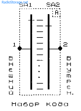
After dialing the internal code (setting the SA2 switches to a user-defined position), the door is slammed. The lock is automatically latched. The number of possible variants of code combinations is equal to the number of switch positions SA1 and SA2 raised to a power equal to the number of typical typesetting elements.
In order to open the lock, it is necessary to dial the required code on the typical typesetting elements of the combination lock. The sequence of typical lock elements is the simplest matching scheme.
If the correct code is entered, the control transition of the transistor VT1 (Fig. 22.10) is closed. As a result, when you press the SB1 "Open" button associated with the door handle, the electromagnetic relay K1 (lock control element) is connected to the power source. The relay will work, its contacts K1.1 will turn on the lock electromagnet, and the lock will open.

If the code is entered incorrectly and the door handle is twitched (pressing the SB1 “Open” button), the voltage through the coil of the relay K1 will go to the base of the transistor VT1, and it will open. At the same time, an unlocking signal will be sent from the resistor R4 to the control electrode of the thyristor VS1, which will turn it on, which will trigger the relay K2. The relay contacts will open the code dialing circuit and turn on the signaling circuit of an unauthorized entry attempt to the protected object (Cs bell, signal lamp, electronic siren, or a combination of them; turn on another actuator).
Re-setting the code will be possible only after pressing the SB2 "Reset" button. Since the current through the winding of relay K1 in the event of an incorrect code set is small (limited by resistor R1 and other circuit elements), relay K1 does not operate. Thus, the user is given only one attempt to open the lock, which sharply limits the possibility of selecting the code by unauthorized persons.
Diodes VD1, VD2 connected in parallel to the relay windings prevent the development of oscillatory processes when switching an inductive load (relay windings). Capacitor C1 eliminates the possibility of false operation of the device due to pickups and transients.
As for other critical devices, which are subject to increased reliability requirements, in the case of the practical use of electronic combination locks, it is advisable to provide backup power to the device from the battery in case of a planned or emergency power outage.
Modified versions of the circuit described above, demonstrating the possibility of powering the device from a voltage source of a different polarity, are shown in Fig. 22.11, 22.12. The principle of their operation has remained the same: the circuits contain a sequence of typesetting elements, a kind of coincidence circuit, as well as a thyristor key, relays and signaling elements.

Compared with the previous circuit, the device (Fig. 22.11) has a reduced sensitivity and therefore requires an individual selection of the value of the resistor R1 included in the thyristor control circuit. When choosing the type of relay K1, it must be taken into account that the current of its operation must significantly exceed the control current of the thyristor. This will prevent false triggering of the device.
A variant of a code lock, made on a transistor analogue of a thyristor, is shown in fig. 22.12. A response delay element is introduced into the circuit - a high-capacity capacitor C1. In this case, the operation of the blocking device is carried out a few moments later. This allows the user to make sure that the door is slammed and the lock is closed.


A slightly different principle of operation is used in the combination lock circuit shown in Fig. 22.13.
As in the previous cases, with the correct code set, the typical elements of the combination lock connected in series will supply voltage to the coil of relay K1 when the SB1 “Open” button is pressed. At the same time, the bell Cs is switched on for a short time, an audible signal sounds, warning about the opening of the lock. In this case, the blocking of the sound signaling device does not occur.
In the initial state, the resistance of the channel source - the drain of the field-effect transistor is small, the control electrode of the thyristor is "short-circuited" to a common wire, the thyristor is closed.
If you enter the wrong code and press the button SB1 "Open." an audible signal also sounds. Since the winding of the relay K1 is connected in series with the resistor R1 (100 kOhm), the current through its winding is small, and the relay does not work. At the same time, the supply voltage is supplied through the relay winding K1 and resistor R2 to the capacitor C2 and charges it in about 5 seconds.
If the button SB1 "Open" pressed for more than 5 seconds, or attempts are made to select a code with periodic twitching of the door (by closing the SB1 button), capacitor C1 will charge. The source resistance - the drain of the field-effect transistor VT1 will increase sharply, the thyristor VS1 will turn on. Relay K2 - thyristor load - with its contacts K2.1 will open the code dialing circuit and turn on an audible or other alarm.
The next access to the lock will be possible only after the circuit is unlocked - by pressing the SB2 "Reset" button. The response delay time (in seconds) is determined by the parameters of the elements of the RC circuit (C2R2), where the capacitance is expressed in microfarads, and the resistance is in MΩ. To vary this time, it is possible to provide for the use of a potentiometer as a resistor R2, which allows you to set any, at the discretion of the user, response delay time from 0 to several seconds. Diode VD2 is designed to instantly discharge capacitor C2 with the “correct” code set and is not a mandatory element.
An electronic combination lock with push-button control (Fig. 22.14) uses /SHOG7-switches (IC DA1 K561KTZ) and an output stage on a transistor VT1 with an executive relay K1 [RL 9 / 99-24].
The above schemes work by pressing several buttons at the same time. The electronic lock (Fig. 22.14) is triggered by successive or simultaneous pressing of the "correct" buttons SB1 - SB4. Pressing the SB1 button causes a high level to be applied to the control input of the DA1.1 key (pin 13 of the microcircuit) and storing this level on the capacitor C1. The DA1.1 key is turned on. Closing the DA1.1 key allows, when the SB2 button is pressed, a high-level voltage is applied to the control input of the next key, etc. - in a chain.

Capacitors C1 - C4 remember the "high level" state for a period of several seconds, determined by the values
resistors R2, R4, R6, R8 connected in parallel with these capacitors. If the SB5 - SBm button is mistakenly pressed during the code dialing or the code dialing time is long, the capacitors C1 - C4 will be discharged. The keys of the switch(es) will open, preventing the lock from being opened.
As in the previous schemes, an incorrect code entry or pressing the call button will cause the capacitor C5 to discharge and prevent further code entry. Instead of buttons SB1 - SB4 in the circuit (Fig. 22.14), typical typesetting elements can be installed (Fig. 22.1). In this case, the lock loses the ability to protect against code selection. How to return this property to him, it is recommended to decide on your own.
Literature: Shustov M.A. Practical Circuitry (Book 1), 2003
In this article, we will talk about how to assemble a simple electronic combination lock. The scope of the combination lock is quite wide, it can be a garage door and a door to a warehouse or a house. The simplicity of the device allows you to assemble a combination lock, the diagram of which will be given below, even for beginner radio amateurs. Parts used are quite common and inexpensive. It will take a little time to assemble the castle.
Each of us keeps some secrets from others. And there is no need to talk about how to safely hide a valuable thing from strangers. I remember as a boy, probably, like any other boy, he raved about treasures and treasures. He took various trinkets, hid them or buried them, then drawing a map, solemnly handed it to his friends and they went in search. Search, of course, is always more interesting.
But those days are gone, and the need to securely lock the doors remains. For example, for garage doors I made according to a simple scheme electronic combination lock. The device is powered by a 12 V battery connected to the charger, which ensures continuous operation of the combination lock. Now, to open the garage, I dial the desired code combination and ... bam - the electronic drive is activated and the lock is open.
Well, let's take a look at code lock diagram, as you can see, it is not particularly difficult, even a beginner radio amateur can handle it.
Combination lock diagram, or rather a description of the work. When the supply voltage is applied through the resistor R1, the capacitor C1 is charged, due to which a high-level signal is supplied to the inputs R of the elements DD1 and DD2 for a short time and sets them to their initial zero state. When the button SB1 of the code lock is actuated on C, the input of the trigger DD1.1 receives a single signal, and since the input D of the trigger is connected to the positive power pole, it (the trigger) goes into a high level state. If you now press the SB2 button, then the DD1.2 trigger will also take a high level state due to the fact that its D input is connected to output 1 of the DD1.1 trigger, and as mentioned above, it is in a single state.
Further, according to the same scheme, if you now press the buttons SB3, SB4 in a row, then the trigger DD2.2 will switch to a high level state and transmit it through output 13 to the base of the transistor VT1, passing the resistor R6. Transistor VT1 will open and open the transistor VT2 itself, which in turn will supply current to relay K1. The relay will energize and activate the electronic code lock actuator.
To disable the mechanism and bring the code lock to its original state, a short-term impact on one button from the group SB5 - SB9 is required. The following will happen, at the R inputs of all triggers, see the diagram, voltage will come in, it is high, and the triggers will switch to the zero state. Naturally, the transistors will close as a result, the relay will de-energize and turn off the actuator.
Please note that if, while dialing a code combination, you accidentally or intentionally press any of the buttons SB5 - SB9, then the triggers will be reset and the lock will not open. If SB1 - SB4 is not sequentially dialed, the order of triggers will be violated, and electronic combination lock also won't work.
Details in code lock diagram shown in the figure apply, the following substitutions in the electronics are possible. Microcircuits DD1 and DD2 can be used similar ones from the K176 series, but the supply voltage should be no more than 9 V. Any KT315 is suitable as a transistor VT1, regardless of its letter index. VT2 is completely dependent on the relay K1, its collector current must ensure the operation of the relay. The relay type depends on the operating current of the electronic lock actuator. A keyboard with buttons from an old electronic calculator can be adapted to the role of a code combination dialer. Diode VD1 can be replaced by any low-power one from the KD521 series or an imported analogue.4.22 (9 Votes)
The coded lock on the door is a locking device, to open which you need to set or indicate the correct combination of numbers. Among them, two main types can be noted - mechanical and electronic. Despite the difference in technology, they have one principle - to open the entrance, you must enter the correct code on the device's keyboard.
Combination locks on the entrance - their advantages and disadvantages
Combination locks on the entrance have both advantages over analogues and disadvantages. The main advantages are:
- no need to make and keep with you the key to the entrance;
- low cost of the mechanism;
- losing the key will not prevent you from getting home;
- the presence of backlighting of keys in electronic and electro-mechanical devices;
- the ability to change the secret code of the lock.
The most significant disadvantages include:
- the possibility of distributing the code among strangers;
- keypads quickly become unusable;
- abrasions on the keys make it possible to select the code for the lock;
- the need to regularly change the code and remember it.
In addition, each type of castle has its own strengths and weaknesses.
Combination locks on the entrance mechanical
When the door to the entrance is slammed, the return spring is cocked in the mechanical device, the start head is located in the bar, and the latch is retracted. Pressing the correct combination of buttons shifts the desired plates, releasing the lock cage. If you release the buttons, the return spring will ensure that the latch takes its original position.
Despite the simplicity of the device, it is rather problematic to assemble it with your own hands.
The only way to open a mechanical lock is to enter the correct code, but despite this, the degree of protection is only sufficient to isolate from random passers-by.

The lock can be installed on both right and left doors. To open it from the inside, you just need to pull the lever. It is recommended to use at least three digits in the code combination.
To recode the lock, you need to remove the screws, remove the set of springs and the lever. Next, you need to arrange the levers of the buttons used for the new code with a bevel to the center of the lock and assemble the device back. You need to check the operation of the lock on the open front door. In winter, use VD-40 on moving parts.
Combination locks on electronics
The electronic lock with a code for the entrance has a more attractive design, a more convenient procedure for changing and entering the code, as well as a number of various related functions. There are enough parts on the radio markets that allow you to assemble such a device with your own hands.
It is advisable to choose locks with a digital code according to the following criteria:
- the ability to unlock the device with a master card;
- key illumination;
- weather protection;
- international certificate;
- the ability to lock different doors with a single key.

The main components of which electronic push-button locks are made:
- The device itself, including the electromagnetic drive of the locking mechanism. In order to ensure the mobility of the bolt of the lock, an electric impulse must be supplied to its electromagnet. This is possible only if the code in the receiver and the combination on the storage medium match. This process takes place on special locks that differ from the usual outgoing pile of wires.
- An outdoor control panel that is a reader that does not include any control electronics. It receives impulses coming from the internal control unit and if the signal code matches, the reader is activated.
- Internal control device, which is the main control center of the electronic lock. It is he who sends an impulse to the electromagnets of the device, which ensures its opening. Most of these locks close, just like any mechanical slamming device.
- Uninterruptible power supply. It is a necessary component for electronic locks - otherwise it will be impossible to enter the room during a power outage. Despite the low power of the device, it can ensure the operation of an electric lock for several days. The UPS is a small appliance located in a hidden place.
Scheme of an electronic combination lock in the entrance - how to assemble it yourself
The code lock works on a 4017 chip. This is a multifunctional crystal and now it will also serve as a watchman, in the form of an easy-to-make code lock with a high level of encryption resistance. In order to find a code for it, you will have to try 10,000 options, and an incorrectly pressed key does not signal an error in any way. The cipher consists of a combination of four digits entered in a certain sequence. Considered code lock scheme:

The execution of such a device is the same as other electronic constipation on microcircuits. Contacts S6-S9 correspond to the numbers that are present in the working code - these are the “necessary” numbers. The keys S1-S5, on the contrary, show numbers that are not in the cipher.
- When power is present, the 3 ms contact leg contains a voltage, denoted by a logical "1".
- When the "S6" key is pressed, this voltage is applied to the input of counter "14" and it is triggered by sending voltage to pin 2.
- The same thing happens after pressing "S7" - "S8" - this sends voltage to pins 4 and 7, respectively.
When the counter captures all four correct pressing of the code digits, the current is applied to contact number 10, which opens the transistor VT2, which supplies power to the relay control circuit. The latter is activated and provides the load connection, as indicated by the LED.
You can assemble an electronic combination lock with your own hands. About it in the video:
Fool-proof protection
If any of the “wrong” buttons (S1-S5) is pressed during the code dialing, voltage is applied to pin 15, which resets the counter, returning the entire circuit to its original position. This is not displayed in any way on the indicators, which greatly complicates the selection of the password.
Unauthorized access can be made almost impossible by simply adding a time relay to pin 15, imperceptibly blocking all keys for at least 60 seconds.

In this case, if you type the code incorrectly, you will have to wait a minute before dialing it again. An attacker will not know this, and even if he accidentally guesses the password, it is not a fact that he will type it during the inactivity of the time relay.
If you know about this feature, then it will take 10-12 thousand minutes to select a password - with your own hands you will have to continuously enter passwords for about 8 days to select the desired combination. The reliability of such a solution increases almost to the maximum values.
The assembled circuit is only part of the work - now it is necessary to adjust the opening / closing of the lock valve. To do this, you can either make a magnet, or use a ready-made activator, for example, an automobile one.
Using these methods, one must be aware that in the first case, when the electricity is turned off, the front door lock will automatically open, and in the second, on the contrary, it will remain closed. Therefore, the second option, equipped with a UPS, is more preferable.
 How to store porcini mushrooms after harvest and for the winter
 Speed regulator for grinder - to make the machine more reliable and functional
 choice of strategic alternatives