DIY free energy generator: diagram. DIY generator: the best ideas and advice on how to make a modern generator with your own hands (instructions with photos and drawings) Do it yourself generator
If the rotor of an induction machine connected to a network with voltage U1 is rotated by means of a prime mover in the direction of the rotating field of the stator, but with a speed n2>
Why We Use Asynchronous Electric Generator
An asynchronous generator is an asynchronous electric machine (electric motor) operating in a generator mode. With the help of a drive motor (in our case, a water motor), the rotor of an asynchronous electric generator rotates in the same direction as the magnetic field. In this case, the slip of the rotor becomes negative, a braking torque appears on the shaft of the asynchronous machine, and the generator transfers energy to the network.
To excite the electromotive force in its output circuit, the residual magnetization of the rotor is used. For this, capacitors are used.
Asynchronous generators are not susceptible to short circuits.
An asynchronous generator is simpler than a synchronous generator (for example, a car generator): if the latter has inductors on the rotor, then the rotor of an asynchronous generator looks like a regular flywheel. Such a generator is better protected from dirt and moisture, it is more resistant to short circuits and overloads, and the output voltage of an asynchronous electric generator has a lower degree of nonlinear distortion. This allows the use of asynchronous generators not only to power industrial devices that are not critical to the form of the input voltage, but also to connect electronic equipment.
It is an asynchronous electric generator that is an ideal current source for devices with an active (ohmic) load: electric heaters, welding converters, incandescent lamps, electronic devices, computer and radio engineering.
Benefits of an asynchronous generator
These advantages include a low clear factor (harmonic distortion), which characterizes the quantitative presence of higher harmonics in the output voltage of the generator. Higher harmonics cause uneven rotation and unnecessary heating of electric motors. In synchronous generators, a clear factor of up to 15% can be observed, and the clear factor of an asynchronous generator does not exceed 2%. Thus, the asynchronous electric generator generates practically only useful energy.
Another advantage of an asynchronous electric generator is that it completely lacks rotating windings and electronic parts that are sensitive to external influences and are quite often prone to damage. Therefore, the asynchronous generator is not subject to wear and tear and can serve for a very long time.
The output of our generators is 220 / 380V AC, which can be used directly to household appliances (for example, heaters), to charge batteries, to connect to a sawmill, as well as to work in parallel with a traditional network. In this case, you will pay the difference between the consumed from the network and generated by the wind turbine. Because voltage goes directly to industrial parameters, then you do not need various converters (inverters) when directly connecting the wind generator to your load. For example, you can directly connect to the sawmill and, in the presence of wind, work as if you simply connected to the 380V network.
If the rotor of an asynchronous machine connected to a network with voltage U1 is rotated by the primary motor in the direction of the rotating field of the stator, but at a speed n2> n1, then the movement of the rotor relative to the stator field will change (in comparison with the motor mode of this machine), since the rotor will overtake the stator field.
In this case, the slip will become negative, and the direction of the emf. E1, induced in the stator winding, and, consequently, the direction of the current I1 will change to the opposite. As a result, the electromagnetic moment on the rotor will also change direction and from rotating (in motor mode) will turn into opposing (in relation to the torque of the prime mover). Under these conditions, the asynchronous machine from the motor will switch to the generator mode, converting the mechanical energy of the prime mover into electrical energy. In the generator mode of an asynchronous machine, the slip can vary in the range
in this case, the frequency of the electromotive force the asynchronous generator remains unchanged, since it is determined by the speed of rotation of the stator field, i.e. remains the same as the frequency of the current in the network to which the asynchronous generator is connected.
Due to the fact that in the generator mode of an asynchronous machine the conditions for creating a rotating field of the stator are the same as in the motor mode (in both modes, the stator winding is connected to the network with voltage U1), and consumes the magnetizing current I0 from the network, then the asynchronous a machine in generator mode has special properties: it consumes reactive energy from the network, which is necessary to create a rotating field of the stator, but gives off active energy to the network, obtained as a result of the transformation of the mechanical energy of the prime mover.
Unlike synchronous generators, asynchronous generators are not subject to the dangers of being out of sync. However, asynchronous generators have not become widespread, which is explained by a number of their disadvantages compared to synchronous generators.
An asynchronous generator can also operate in autonomous conditions, i.e. without being included in the general network. But in this case, to obtain the reactive power required for magnetizing the generator, a bank of capacitors is used, connected in parallel with the load on the generator terminals.
An indispensable condition for such an operation of asynchronous generators is the presence of residual magnetization of the rotor steel, which is necessary for the generator self-excitation process. Small emf Eost induced in the stator winding creates a small reactive current in the capacitor circuit and, consequently, in the stator winding, which increases the residual flux Fost. In the future, the self-excitation process develops, as in the parallel excitation direct current generator. By changing the capacitance of the capacitors, you can change the magnitude of the magnetizing current, and, consequently, the magnitude of the voltage of the generators. Due to the excessive bulkiness and high cost of capacitor banks, self-excited asynchronous generators have not become widespread. Asynchronous generators are used only in power plants of an auxiliary value of low power, for example, in wind power plants.
DIY generator
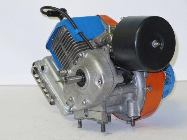
In my power plant, the current source is an asynchronous generator driven by an air-cooled two-cylinder gasoline engine UD-25 (8 hp, 3000 rpm). As an asynchronous generator without any alterations, you can use a conventional asynchronous electric motor with a rotational speed of 750-1500 rpm and a power of up to 15 kW.
The frequency of rotation of the asynchronous generator in normal operation must exceed the rated (synchronous) value of the number of revolutions of the used electric motor by 10%. This can be done as follows. The electric motor is connected to the network and the idle speed is measured with a tachometer. The belt drive from the engine to the generator is calculated in such a way as to provide a slightly increased generator speed. For example, an electric motor with a rated speed of 900 rpm is idling at 1230 rpm. In this case, the belt drive is designed to provide a generator speed of 1353 rpm.
The windings of the induction generator in my installation are connected by a "star" and produce a three-phase voltage of 380 V. To maintain the rated voltage of the induction generator, it is necessary to correctly select the capacitance of the capacitors between each phase (all three capacities are the same). To select the required capacity, I used the following table. Before acquiring the necessary skill in the operation, you can check the heating of the generator by touch to avoid overheating. Heating indicates that too much tank is connected.
Capacitors are suitable type KBG-MN or others with an operating voltage of at least 400 V. When the generator is turned off, an electric charge remains on the capacitors, therefore, precautions must be taken against electric shock. Capacitors should be protected securely.
When working with a 220 V manual power tool, I use a TSZI step-down transformer from 380 V to 220 V. When a three-phase motor is connected to a power plant, it may happen that the generator will not “master” it the first time. Then you should give a series of short-term start-ups of the engine until it picks up speed, or spin it up manually.
Stationary asynchronous generators of this kind, used for electrical heating of a residential building, can be driven by a wind turbine or a turbine installed on a small river or stream, if there are any near the house. At one time in Chuvashia, the Energozapchast plant produced a generator (micro-hydroelectric power station) with a capacity of 1.5 kW based on an asynchronous electric motor. VP Beltyukov from Nolinsk made a wind turbine and also used an asynchronous motor as a generator. Such a generator can be set in motion using a walk-behind tractor, mini tractor, motor scooter engine, car, etc.
I installed my power plant on a small lightweight uniaxial trailer - a frame. For work outside the farm, I load the necessary power tools into the machine and attach my installation to it. With a rotary mowing machine I mow hay, with an electric tractor I plow the soil, harrow, plant, huddle. For such work, complete with the station, I drive a coil with a four-core KRPT cable. There is one point to keep in mind when winding the cable. If wound in the usual way, then a solenoid is formed, in which there will be additional losses. To avoid them, the cable must be folded in half and wound around the spool, starting from the fold.
In late autumn, you have to harvest firewood for the winter from dead wood. Again, I use a power tool. At my summer cottage, using a circular saw and a planer, I process material for carpentry.
As a result of a long test of the operation of our Sailing wind generator with a traditional excitation circuit of an asynchronous motor (AM), based on the use of a magnetic starter as a switch, a number of shortcomings were revealed, which led to the creation of the Control Cabinet. Which has become a universal device for turning any Asynchronous Motor into a Generator! Now it is enough to connect the wires from the motor blood pressure to our control unit and the generator is ready.
How To Turn Any Asynchronous Motor Into A Generator - A House Without A Foundation
How To Turn Any Asynchronous Motor Into A Generator - A House Without Foundations Why We Use An Asynchronous Electric Generator An Asynchronous Generator is one that operates in a generator mode
For the needs of the construction of a private residential house or a summer residence, a home craftsman may need an autonomous source of electrical energy, which can be bought in a store or assembled with your own hands from available parts.
A home-made generator is capable of operating on energy from gasoline, gas or diesel fuel. To do this, it must be connected to the engine through a shock-absorbing clutch, which ensures smooth rotation of the rotor.
If local environmental conditions permit, for example, frequent winds blow or a source of running water is nearby, then a wind or hydraulic turbine can be created and connected to an asynchronous three-phase motor to generate electricity.
Due to such a device, you will have a constantly working alternative source of electricity. It will reduce the consumption of energy from public networks and allow you to save on its payment.
In some cases, it is permissible to use a single-phase voltage to rotate an electric motor and transfer torque to it to a home-made generator to create its own three-phase symmetrical network.
How to choose an induction motor for a generator by design and characteristics
Technological features
The basis of a home-made generator is an asynchronous three-phase electric motor with:
Stator device
The stator and rotor magnetic cores are made of insulated plates of electrical steel, in which grooves are created to accommodate the winding wires.

Three separate stator windings can be connected at the factory as follows:
Their leads are connected inside the terminal box and connected with jumpers. The power cable is also mounted here.

In some cases, wires and cables can be connected in other ways.

Symmetrical voltages are applied to each phase of the asynchronous motor, shifted along the angle by a third of the circle. They generate currents in the windings.

It is convenient to express these quantities in vector form.

Features of the design of the rotors
Phase-rotor motors
They are provided with a stator winding, and the leads from each are connected to slip rings, which provide electrical contact with the starting and adjustment circuit through the pressure brushes.
This design is rather complicated to manufacture and expensive. It requires periodic monitoring of the work and qualified maintenance. For these reasons, it makes no sense to use it in this design for a homemade generator.
However, if there is a similar motor and there is no other application for it, then the conclusions of each winding (those ends that are connected to the rings) can be short-circuited among themselves. In this way, the phase rotor will turn into a squirrel-cage rotor. It can be connected according to any scheme discussed below.
Squirrel cage motors
Aluminum is poured inside the grooves of the rotor magnetic circuit. The winding is made in the form of a rotating squirrel cage (for which it received such an additional name) with short-circuited jumper rings at the ends.
This is the simplest motor circuit, which has no moving contacts. Due to this, it works for a long time without the intervention of electricians, and is distinguished by increased reliability. It is recommended to use it to create a homemade generator.
Motor casing designations

In order for a homemade generator to work reliably, you need to pay attention to:
- IP class, which characterizes the quality of protection of the case against environmental influences;
- power consumption;
- speed;
- connection diagram of the windings;
- permissible load currents;
- Efficiency and cosine φ.
The connection diagram of the windings, especially in old motors that have been in operation, should be called, checked by electrical methods. This technology is described in detail in the article on connecting a three-phase motor to a single-phase network.

The principle of operation of an induction motor as a generator
Its implementation is based on the method of reversibility of an electric machine. If the motor, disconnected from the mains voltage, begins to forcibly rotate the rotor at the design speed, then an EMF will be induced in the stator winding due to the presence of residual energy of the magnetic field.
It remains only to connect a capacitor bank of the appropriate rating to the windings and a capacitive leading current, which has the character of magnetizing, will flow through them.
In order for the generator to self-excite, and a symmetrical system of three-phase voltages was formed on the windings, it is necessary to select the capacitance of the capacitors greater than a certain critical value. In addition to its value, the engine design naturally affects the output power.
For normal production of three-phase energy with a frequency of 50 Hz, it is necessary to maintain the rotor speed exceeding the asynchronous component by the slip value S, which lies in the range S = 2 ÷ 10%. It needs to be kept at the synchronous frequency.
Departure of the sinusoid from the standard frequency value will adversely affect the operation of equipment with electric motors: saws, planers, various machine tools and transformers. This practically does not affect resistive loads with heating elements and incandescent lamps.
Wiring diagrams
In practice, all common methods of connecting the stator windings of an induction motor are used. By choosing one of them, they create different conditions for the operation of the equipment and generate a voltage of certain values.
Star schematics
A popular option for connecting capacitors
The connection diagram of an asynchronous motor with star-connected windings for operation as a generator of a three-phase network has a standard form.

Scheme of an asynchronous generator with capacitors connected to two windings
This option is quite popular. It allows three groups of consumers to be powered from two windings:

The working and starting capacitors are connected to the circuit by separate switches.
Based on the same scheme, you can create a homemade generator with capacitors connected to one winding of an induction motor.
Triangle diagram
When assembling the stator windings in a star pattern, the generator will produce a three-phase voltage of 380 volts. If we switch them to a triangle, then - 220.

The three schemes shown above in the pictures are basic, but not the only ones. On their basis, other connection methods can be created.
How to calculate the characteristics of a generator by engine power and capacitor capacitance
To create normal operating conditions for an electric machine, it is necessary to maintain the equality of its rated voltage and power in the modes of the generator and the electric motor.
For this purpose, the capacitance of the capacitors is selected taking into account the reactive power Q generated by them at various loads. Its value is calculated by the expression:
From this formula, knowing the motor power, to ensure full load, you can calculate the capacity of the capacitor bank:
However, the operating mode of the generator should be taken into account. At idle, the capacitors will unnecessarily load the windings and heat them. This leads to large losses of energy, overheating of the structure.
To eliminate this phenomenon, capacitors are connected in steps, determining their number depending on the applied load. To simplify the selection of capacitors for starting an induction motor in generator mode, a special table has been created.
Starting capacitors of the K78-17 series and the like with an operating voltage of 400 volts and more are well suited for use as part of a capacitive battery. It is quite permissible to replace them with metal and paper counterparts with appropriate denominations. They will have to be collected in parallel.

It is not worth using models of electrolytic capacitors to work in the circuits of an asynchronous home-made generator. They are designed for direct current circuits, and when passing a sinusoid that changes in direction, they quickly fail.
There is a special scheme for their connection for such purposes, when each half-wave is directed by diodes to its own assembly. But it is quite complicated.
Constructive execution
An autonomous power plant device must fully meet the requirements for safe operation of operating equipment and be performed by a single module, including a hinged electrical panel with devices:
- measurements - with a voltmeter up to 500 volts and a frequency meter;
- switching loads - three switches (one common supply voltage from the generator to the consumer circuit, and the other two connect capacitors);
- protection - an automatic switch that eliminates the consequences of short circuits or overloads and an RCD (residual current device), which saves workers from insulation breakdown and phase potential hitting the case.
Main power supply redundancy
When creating a home-made generator, it is necessary to provide for its compatibility with the grounding scheme of the working equipment, and in case of autonomous operation, it must be reliably connected to the ground loop.
If a power plant is created for backup power supply of devices operating from the state network, then it should be used when the voltage from the line is disconnected, and when restored, it should be stopped. To this end, it is enough to install a switch that controls all phases at the same time or connect a complex automatic system for turning on the backup power.
Voltage selection
The 380 volt circuit has an increased risk of injury to a person. It is used in extreme cases, when the phase value of 220 cannot be dispensed with.
Generator overload
Such modes create unnecessary heating of the windings with the subsequent destruction of the insulation. They arise when the currents passing through the windings are exceeded due to:
- incorrect selection of capacitor capacitance;
- connection of consumers of increased power.
In the first case, it is necessary to carefully monitor the thermal regime during idle. With excessive heating, it is necessary to correct the capacitance of the capacitors.
Features of consumer connection
The total power of a three-phase generator consists of three parts generated in each phase, which is 1/3 of the total. The current passing through one winding should not exceed the rated value. This must be taken into account when connecting consumers, distribute them evenly in phases.
When a home-made generator is created to operate on two phases, then it cannot safely generate electricity more than 2/3 of the total, and if only one phase is involved, then only 1/3.
Frequency control
The frequency meter allows you to monitor this indicator. When it was not installed in the design of a home-made generator, then you can use an indirect method: at idle, the output voltage exceeds the nominal 380/220 by 4 ÷ 6% at a frequency of 50 Hz.
How to make a homemade generator from an asynchronous motor, DIY apartment design and renovation
Tips for a home craftsman on making a homemade generator from an asynchronous three-phase electric motor with diagrams with his own hands. pictures and videos
How to make a homemade generator from an induction motor
Hello everyone! Today we will consider how to make a homemade generator from an asynchronous motor with our own hands. This question has been of interest to me for a long time, but somehow there was no time to take on its implementation. Now let's get a little bit of theory.
If you take and spin an asynchronous electric motor from some prime mover, then following the principle of reversibility of electric machines, you can make it generate an electric current. To do this, you need to rotate the shaft of the induction motor with a frequency equal to or slightly higher than the asynchronous frequency of its rotation. As a result of residual magnetism in the magnetic circuit of the electric motor, some EMF will be induced at the terminals of the stator winding.
Now we take and connect to the terminals of the stator winding, as shown in the figure below, non-polar capacitors C.
 In this case, a leading capacitive current will begin to flow through the stator winding. It will be called magnetizing. Those. self-excitation of the asynchronous generator will occur and the EMF will increase. The EMF value will depend on the characteristics of both the electrical machine itself and the capacitance of the capacitors. Thus, you and I have turned a conventional asynchronous electric motor into a generator.
Now let's talk about how to choose the right capacitors for a homemade generator from an induction motor. The capacity must be selected so that the generated voltage and the output power of the asynchronous generator correspond to the power and voltage when it operates as an electric motor. For data, see the table below. They are relevant for the excitation of asynchronous generators with a voltage of 380 volts and a rotation frequency of 750 to 1500 rpm.

With an increase in the load on the induction generator, the voltage at its terminals will tend to fall (the inductive load on the generator will increase). To maintain the voltage at a given level, it is necessary to connect additional capacitors. To do this, you can use a special voltage regulator, which, when the voltage at the generator stator outputs drops, will connect additional capacitor banks with the help of contacts.
The generator speed in normal mode should exceed the synchronous speed by 5-10 percent. That is, if the rotational speed is 1000 rpm, then you need to spin it at a frequency of 1050-1100 rpm.
One big plus of an asynchronous generator is that you can use a conventional asynchronous electric motor without alterations. But it is not recommended to get carried away and make generators from electric motors with a capacity of more than 15-20 kV * A. A home-made generator from an asynchronous motor is an excellent solution for those who do not have the opportunity to use the classic kronotex laminate generator. Good luck with everything and bye!
How to make a homemade generator from an induction motor, DIY repair
How to make a homemade generator from an induction motor Hello everyone! Today we will consider how to make a homemade generator from an asynchronous motor with our own hands. This question has been me for a long time
A generator is a device that produces products that generate electrical energy or convert it into another. What is the device, how to make a generator, what is the principle of its operation, what is the difference from a synchronous generator? We will talk about this further.
A generator is an electrical machine that converts mechanical energy into current electricity. In most cases, a rotational type of magnetic field is used for this. The apparatus consists of a relay, a rotating inductor, slip rings, terminal, sliding brush, diode bridge, diodes, slip ring, stator, rotor, bearings, rotor shaft, pulley, impeller and front cover. Often, a coil with an electromagnet is included in the design, which generates energy.
DIY generator
It is important to note that the generator comes in alternating current and direct current. In the first case, eddy currents are not formed, the apparatus can operate under extreme conditions and has a reduced weight. In the second case, the generator does not need increased attention and has more resources.
The alternator is synchronous and asynchronous. The first is a unit that works as a generator, where the number of stator rotations performed is equal to the rotor. The rotor generates a magnetic field and creates an EMF in the stator.
Note! The result is a permanent electric magnet. Among the advantages, the high stability of the generated voltage is noted, and the disadvantages are current overload, since at an overestimated load, the regulator increases the current in the rotor winding.

Synchronous apparatus device
The asynchronous apparatus consists of a squirrel-cage rotor and exactly the same stator as the previous model. At the moment of rotation of the rotor, the induction generator induces an electric current and the magnetic field creates a sinusoidal voltage. Since it has no connection with the rotor, there is no possibility to artificially regulate the voltage and current. These parameters change under electrical load on the starter winding.

Asynchronous device device
Operating principle
Any generator acts according to an electromagnetic inductive law, due to the induction of an electric current in a closed frame by the intersection of a rotating magnetic field created using permanent magnets or windings. The electromotive force enters the closed loop from the collector and the brush assembly together with the magnetic flux, the rotor rotates and generates voltage. Thanks to the spring-loaded brushes, which are pressed against the plate collectors, electric current is transmitted to the output terminals. Then it goes to the user's network and is distributed to electrical equipment.

Principle of operation
Difference from a synchronous generator
A synchronous gasoline generator is not overloaded due to transient modes that are associated with starting under load from consumers of similar power. It is the source of reactive power, while the asynchronous one consumes it. The first is not afraid of overloads in the supplied mode thanks to the automatic control system through the connection, which is inverse to the current with the voltage in the wire. The second has an artificially unregulated adhesion force of the rotor electromagnetic field.
Note! It is important to understand that the asynchronous version is more popular due to its simple design, unpretentiousness, lack of need for qualified technical maintenance and comparative cheapness. It is placed when: there are no high requirements for frequency with voltage; it is supposed to operate the unit in a dusty place; there is no way to overpay for another variety.
Application area
An alternator is a multifunctional device, thanks to which energy can be transmitted over long distances and at the same time quickly redistributed. In addition, it is converted into light, heat, mechanical and other energy according to instructions. Easy to manufacture. Therefore, the area of their application is extensive. Today, such devices are used everywhere: both in industry and in everyday life. They are equipped with a powerful motor.
For example, an electric and wind generator will be useful at a time when the volt network is disconnected, an accident occurs at a power plant, and additional energy will be needed in the engine.
The gasoline and magnetic generator, due to its light weight and compactness, can be transported and used in agriculture, in the country, in the forest. It will serve as rapid response equipment and help create emergency lighting.

Application area
Device classification
The device classification is extensive. Today it can be asynchronous and synchronous, with a fixed rotor or stator, single-phase, two-phase and three-phase, with independent or self-excited excitation, with excitation windings or excitation from a permanent magnet.
Note! It is worth noting that at the moment three-phase models are more popular due to the rotating circular magnetic field, the equilibrium of the system, operation in several modes and high levels of efficiency.

Equipment classification
Device assembly diagram
Do-it-yourself electric generators for 220 can be assembled by analogy with a production model. This may require video tutorials or tutorials. Then you need to correctly connect all the devices of one system. This can be done according to the star or triangle pattern.
In the first case, the electrical connection occurs for all ends of the windings of one point, and in the second case, a sequential type of winding generator connections is provided. It is important to note that these circuits can only be used if the phase load is uniform. Then the topic of how to make a generator at home will be relevant.

Star connection diagram
In general, a generator is a device that converts mechanical energy into electrical energy using a wire version of a magnetic field coil. According to the number of phases, the units are available with one, two and three phases.

Triangle wiring diagram
You can do it yourself today using the special scheme indicated above.
The universal use of electricity in all spheres of human activity is associated with the search for free electricity. Because of what a new milestone in the development of electrical engineering was an attempt to create a free energy generator, which would significantly reduce the cost or nullify the cost of generating electricity. The most promising source for this task is free energy.
What is free energy?
The term free energy arose at the time of the large-scale introduction and operation of internal combustion engines, when the problem of obtaining electric current directly depended on the coal, wood or oil products expended for this. Therefore, free energy is understood as such a force, for the extraction of which there is no need to burn fuel and, accordingly, consume any resources.
The first attempts to scientifically substantiate the possibility of obtaining free energy were laid by Helmholtz, Gibbs and Tesla. The first of them developed a theory of creating a system in which the generated electricity must be equal to or more than that consumed for the initial start-up, that is, to obtain a perpetual motion machine. Gibbs expressed the possibility of obtaining energy during the course of a chemical reaction so long that it was enough for a full power supply. Tesla observed energy in all natural phenomena and formulated a theory about the presence of ether - a substance that permeates everything around us.
Today you can observe the implementation of these principles for obtaining free energy in the. Some of them have long been at the service of humanity and help to obtain alternative energy from wind, sun, rivers, ebb and flow. These are the same solar panels, hydroelectric power plants, which helped to harness the forces of nature, which are freely available. But along with the already substantiated and implemented free energy generators, there are concepts of fuel-free engines that try to get around the law of conservation of energy.
Energy conservation problem
The main stumbling block in getting free electricity is the law of conservation of energy. Due to the presence of electrical resistance in the generator itself, connecting wires and in other elements of the electrical network, according to the laws of physics, there is a loss of output power. Energy is consumed and to replenish it requires constant replenishment from the outside, or the generation system must create such an excess of electrical energy that it is sufficient both to supply the load and to maintain the generator. From a mathematical point of view, a free energy generator should have an efficiency of more than 1, which does not fit into the framework of standard physical phenomena.
Tesla generator circuit and design
Nikola Tesla became the discoverer of physical phenomena and created on their basis many electrical devices, for example, Tesla transformers, which are used by mankind to this day. Throughout the history of his activity, he has patented thousands of inventions, among which there is more than one free energy generator.
Rice. 1: Tesla Free Energy Generator
Look at Figure 1, here is the principle of generating electricity using a free energy generator assembled from Tesla coils. This device involves obtaining energy from the ether, for which the coils that make up it are tuned to the resonant frequency. To obtain energy from the surrounding space in this system, the following geometric relationships must be observed:
- winding diameter;
- wire cross-section for each of the windings;
- the distance between the coils.
Today, various applications of Tesla coils in the design of other free energy generators are known. True, it has not yet been possible to achieve any significant results from their application. Although some inventors claim the opposite, and keep the result of their developments in the strictest confidence, demonstrating only the final effect of the generator. In addition to this model, other inventions of Nikola Tesla are known, which are generators of free energy.
Magnetic free energy generator
The effect of interaction between a magnetic field and a coil is widely used in. And in a free energy generator, this principle is used not to rotate a magnetized shaft by supplying electrical impulses to the windings, but to supply a magnetic field to an electric coil.
The impetus for the development of this direction was the effect obtained when voltage was applied to an electromagnet (a coil wound on a magnetic circuit). In this case, a nearby permanent magnet is attracted to the ends of the magnetic circuit and remains attracted even after disconnecting the power from the coil. A permanent magnet creates a constant magnetic field in the core, which will hold the structure until it is torn off by physical impact. This effect was applied to create a permanent magnet free energy generator circuit.
 Rice. 2. The principle of operation of the generator on magnets
 Look at Figure 2, to create such a free energy generator and power the load from it, it is necessary to form an electromagnetic interaction system, which consists of:
- starting coil (I);
- locking coil (IV);
- feed coil (II);
- support coil (III).
The circuit also includes a control transistor VT, a capacitor C, diodes VD, a limiting resistor R and a load Z H.
This free energy generator is turned on by pressing the "Start" button, after which the control pulse is fed through VD6 and R6 to the base of the transistor VT1. When a control pulse arrives, the transistor opens and closes the current flow circuit through the starting coils I. After that, the electric current flows through the coils I and excites the magnetic circuit, which will attract the permanent magnet. The lines of force of the magnetic field will flow along the closed loop of the magnetic core and the permanent magnet.
EMF is induced from the flowing magnetic flux in coils II, III, IV. The electric potential from the IV coil is fed to the base of the transistor VT1, creating a control signal. EMF in coil III is designed to maintain the magnetic flux in the magnetic circuits. EMF in coil II provides power supply to the load.
The stumbling block in the practical implementation of such a free energy generator is the creation of a variable magnetic flux. To do this, it is recommended to install two circuits with permanent magnets in the circuit, in which the lines of force have an opposite direction.
In addition to the above generator of free energy on magnets, today there are a number of similar devices designed by Searl, Adams and other developers, the generation of which is based on the use of a constant magnetic field.
Nikola Tesla's followers and their generators
The seeds of incredible inventions sown by Tesla gave rise to an unquenchable thirst in the minds of applicants to realize the fantastic ideas of creating a perpetual motion machine and send mechanical generators to the dusty shelf of history. The most famous inventors used the principles outlined by Nikola Tesla in their devices. Let's consider the most popular ones.
Lester Hendershot
Hendershot developed a theory about the possibility of using the earth's magnetic field to generate electricity. Lester introduced the first models back in the 1930s, but they were never in demand by his contemporaries. Structurally, the Hendershot generator consists of two counter-wound coils, two transformers, capacitors and a moving solenoid.
 Rice. 3: General view of the Hendershot generator
 The operation of such a free energy generator is possible only with its strict orientation from north to south, therefore, a compass is necessarily used to set up the operation. The winding of the coils is carried out on wooden bases with multidirectional winding in order to reduce the effect of mutual induction (when the EMF is induced in them, the EMF will not be induced in the opposite direction). In addition, the coils must be tuned by a resonant circuit.
John Bedini
Bedini presented his free energy generator in 1984, a feature of the patented device was an energizer - a device with a constant torque that does not lose speed. This effect was achieved by installing several permanent magnets on the disk, which, when interacting with an electromagnetic coil, create pulses in it and are repelled from the ferromagnetic base. Thanks to this, the free energy generator received a self-feeding effect.
Later Bedini generators became famous through one school experiment. The model turned out to be much simpler and did not represent something grandiose, but it was able to perform the functions of a generator of free electricity for about 9 days without outside help.
 Rice. 4: schematic diagram of the Bedini generator
 Look at figure 4, here is a schematic diagram of a free energy generator of that very school project. It uses the following elements:
- rotating disc with several permanent magnets (energizer);
- coil with a ferromagnetic base and two windings;
- battery (in this example, it was replaced with a 9V battery);
- a control unit of a transistor (T), a resistor (P) and a diode (D);
- the current collection is organized from an additional coil that feeds the LED, but it is also possible to produce power from the battery circuit.
With the start of rotation, permanent magnets create magnetic excitation in the coil core, which induces an EMF in the windings of the output coils. Due to the direction of the turns in the starting winding, current begins to flow, as shown in the figure below, through the starting winding, resistor and diode.
 Rice. Step 5 - starting the Bedini generator
 When the magnet is directly above the solenoid, the core is saturated and the stored energy becomes enough to open the transistor T. When the transistor is opened, the current begins to flow in the working winding, which recharges the battery.
 Figure 6: Starting the float winding
 Energy at this stage becomes enough to magnetize the ferromagnetic core from the working winding, and it receives a pole of the same name with a magnet located above it. Due to the magnetic pole in the core, the magnet on the spinning wheel is repelled from this pole and accelerates the further movement of the energizer. With the acceleration of movement, impulses in the windings appear more and more often, and the LED from the flashing mode goes into a constant glow.
Alas, such a free energy generator is not a perpetual motion machine; in practice, it allowed the system to work tens of times longer than it could operate on a single battery, but over time it still stops.
Tariel Kapanadze
Kapanadze developed a model of his free energy generator in the 80s-90s of the last century. The mechanical device was based on the work of an improved Tesla coil, as the author himself argued, a compact generator could power consumers with a power of 5 kW. In the 2000s, an attempt was made to build an industrial-scale Kapanadze generator of 100 kW in Turkey, according to its technical characteristics, it needed only 2 kW for start-up and operation.
 Rice. 7: schematic diagram of the Kapanadze generator
 The figure above shows a schematic diagram of a free energy generator, but the main parameters of the circuit remain a trade secret.
Practical circuits of free energy generators
Despite the large number of existing free energy generator circuits, very few of them can boast of real results that could be checked and repeated at home.
 Rice. 8: working diagram of a Tesla generator
 Figure 8 above shows a diagram of a free energy generator that you can repeat at home. This principle was stated by Nikola Tesla, for his work, a metal plate is used, isolated from the ground and located on a hill. The plate is a receiver of electromagnetic oscillations in the atmosphere; this includes a fairly wide range of radiation (solar, radio-magnetic waves, static electricity from the movement of air masses, etc.)
The receiver is connected to one of the capacitor plates, and the second plate is grounded, which creates the required potential difference. The only stumbling block to its industrial implementation is the need to isolate a large plate on a hill to supply at least a private house.
Modern look and new developments
Despite the widespread interest in the creation of a free energy generator, they still cannot oust the classical method of generating electricity from the market. The developers of the past, who put forward bold theories about a significant reduction in the cost of electricity, lacked the technical perfection of equipment or the parameters of the elements could not provide the desired effect. And thanks to scientific and technological progress, mankind receives more and more inventions that make the embodiment of the free energy generator already tangible. It should be noted that today free energy generators operating on the power of the sun and wind have already been obtained and are being actively operated.
But, at the same time, on the Internet you can find offers to purchase such devices, although most of them are dummies created with the aim of deceiving an uninformed person. And a small percentage of actually working generators of free energy, whether on resonant transformers, coils or permanent magnets, can only cope with powering low-power consumers, they cannot provide electricity, for example, to a private house or lighting in the yard. Free energy generators are a promising direction, but their practical implementation has not yet been implemented.
An electric generator is a device designed to generate electricity for specific purposes. A homemade device is capable of performing the function of a source only if certain conditions are met. It will hardly be possible to assemble it completely "from scratch" at home. The only way to make an electric generator with your own hands is to use other mechanisms that work on the same principle for these purposes. An old engine from a walk-behind tractor or a wind turbine is most suitable. Assembly work will require a lot of effort and money, as well as the presence of some experience. If there is no complete confidence in success, it is best to purchase an expensive but effective branded product.
Device and principle of operation
DC generator
Before making an electric generator with your own hands in a purely home environment, you will need to familiarize yourself with its design and figure out how it works. The basis of such a device is a multi-section winding located on a stationary stator. A movable armature (rotor) is placed inside, in the design of which a permanent magnet is provided. This part of the generator, through a special drive mechanism, is connected to a propeller driven by a wind turbine or a gasoline engine. Alternative energy resources can be used as a drive (water or heat generated by burning wood, for example).
 Operating procedure:
- when the rotor rotates, its magnetic lines cross the e / m field of the stator coils;
- due to this, according to Faraday's law of induction, an EMF of the corresponding magnitude is induced in them;
- a load is connected to the stator coils, the alternating current in which changes in a sinusoidal manner.
Depending on the number of stator windings and the switching circuit, you can get a single-phase 220 Volt or a three-phase (380 Volt) home-made generator.
This principle of operation applies to all samples of electrical machines, without exception (regardless of the type of drive).
An efficiently working electric current generator, made with your own hands from auxiliary parts, is able to solve a number of everyday problems. Homemade products are traditionally used to generate enough electrical energy to power a household's electrical grid. In addition, not very powerful welding equipment or a water pump for watering the beds in the country can work from the unit. The product made in the form of a wind generator is allowed to be operated in the country and on a hike.
DIY generator assembly
Instructions for assembling current generators with your own hands involves performing work in several stages. They begin with the preparatory stage, at which it is necessary to stock up on initial blanks and the required material.
Preparatory stage
Mole walk-behind tractor engine
For assembly you will need:
- An old electric motor from a walk-behind tractor or wind turbine with a working stator winding. There are also popular options for using motors from an old washing machine or water pump.
- To equalize the output current, it is advisable to make a rectifier (converter) in advance.
- To facilitate the launch of the future device and self-excitation of its 220 volt windings, a high-voltage (at least 400-500 volts) capacitor with a capacity of 3-7 microfarads will be required. Its exact value is selected depending on the planned power of the generator.
Assembly requires long pieces of securely insulated wire, adhesive protective tape, and an assembly tool (diagonal cutters, pliers, and a set of screwdrivers). You should also stock up on a powerful soldering iron necessary to restore contacts in broken windings of an old motor.
You should worry in advance about the grounding of the case of the future product, which generates a voltage that is dangerous for humans.
Upon completion of preparation, proceed to the assembly, the order of which depends on the selected source sample.
Wind turbine - the simplest option

Diy wind generator diagram
The easiest method to implement is to manufacture a wind generator assembled from scrap parts and ready-made modules. Very simple electrical loads can work from it, the power of which does not exceed 100 watts (a light bulb, for example). To make it you will need:
- (it will work as a generator).
- Bottom bracket and main sprocket from an adult bike.
- Roller chain from an old motorcycle.
- Bicycle frame.
A good master will probably find all these blanks at hand in the garage, from which an electric generator is easily assembled with his own hands.
To familiarize yourself with this procedure, it is advisable to watch a video that describes in detail the procedure for making a windmill.
An asterisk is installed on the shaft of such an electric motor, which, by means of a roller chain, is driven into rotation from homemade wind blades attached to a bicycle frame. With their help, the translational movement of the wind is converted into a rotational moment. This design is capable of generating a load current of up to 6 Amperes at a voltage of 14 Volts.
Power plant based on a generator from a walk-behind tractor

The structure of the generator from the walk-behind tractor
A more complex version involves the use of an old walk-behind tractor used as a drive. The function of a generator in this system is performed by an asynchronous motor with a rotational speed of up to 1600 rpm and an effective power of up to 15 kW. During the assembly process, its drive mechanism is connected to the axis of the walk-behind tractor by means of pulleys and a belt. The diameter of the pulleys is chosen so that the rotational speed of the electric motor converted into a generator is 15% higher than the nameplate value.
Advantages and disadvantages

Unlike factory-made, home-made gasoline generators, made at home, usually have large dimensions and weight.
The advantages of a hand-assembled product include:
- The ability not to depend on interruptions in the operation of power substations, getting the required minimum of electricity on your own.
- The homemade generator is adjusted to the operating parameters corresponding to the specific requests of the user.
- Its manufacture instead of a purchased product will save significant amounts (especially in a situation with 380 volt asynchronous machines).
The disadvantages of self-production are considered possible difficulties with assembling a specific type of product and the need to spend money on energy (fuel, for example).
Before making a household electricity generator, you need to familiarize yourself with the rules for its operation. Their essence is as follows:
- Before starting the device, all loads are disconnected so that it runs idle.
- The presence of oil in the working compartment of the generator is checked - its level must be above the set mark;
- The device remains switched on for about 5 minutes, after which it is allowed to connect the load.
In accordance with the rules of operation and maintenance of such generators, the most suitable mode of operation is considered to be the use of its power at 70% of the limit value. If this requirement is met, the equipment will not overheat and can easily cope with the design load.
Unfortunately, power supply organizations often cannot cope with providing private households with electricity. Due to power outages, the owners of summer cottages and country cottages are forced to turn to alternative sources of electricity. The most common of these is the generator.
Features of an electric generator and its scope
An electric generator is a mobile device used to convert and store electricity. The principle of operation of this device is simple, which allows you to make it yourself. A simple generator circuit can be easily found on the Internet.

A hand-built unit will not compete with a factory-assembled product, but it is the best solution if you want to save a significant amount of money.

Electric generators have a fairly wide range of applications. As you can see in the photo of self-made generators, they can be used in wind farms, in welding works, and also as an autonomous device to support electricity in private homes.

The generator is switched on by the incoming voltage. To do this, the device is connected to a power source, but this is not rational for a mini-power plant, because it must generate electric current, and not consume it to start.


As a result, models equipped with the ability to sequentially switch capacitors or a self-excitation function are especially popular.
Nuances you need to know to create an electric generator
Buying a generator is quite expensive. Therefore, more and more zealous owners are resorting to making the unit with their own hands. The simplicity of the principle of operation and design solution allows you to assemble an electric generating device in just a couple of hours.

How to make a generator with your own hands?
The first step is to set up all equipment so that the rotation speed exceeds the speed of the electric motor. After measuring the amount of rotation of the motor, add another 10%. You will get the speed at which the generator should be running.

Step two - alteration of the generator for yourself using capacitors. It is very important to correctly determine the required capacity.

The third step is installing capacitors. Here you must strictly follow the calculation. In addition, you need to ensure the quality of the insulation. That's it - the assembly of the generator is complete.


Workshop on making an asynchronous generator
One of the most common types of home-made generators is an asynchronous electric generator. This is due to its simple operating principle and good technical characteristics.

What is needed to make such a generator with your own hands? First of all, you need an induction motor. Its distinctive feature is short-circuited loops instead of a magnet on the rotor. You will also need capacitors.

Manufacturing instruction
Connect a voltmeter to any of the motor windings and spin the shaft. The voltmeter will show the presence of voltage, which is taken due to the residual magnetization of the rotor.

It's not a generator yet. Let's try to create a magnetic field using rotor turns. When the electric motor is turned on, the short-circuited turns of the rotor are magnetized. A similar result can be obtained when the device is operating in the "generator" mode.


We put a shunt on one of the stator windings using a non-electrical capacitor. We will unscrew the shaft. The value of the voltage that appears will eventually become equal to the rated voltage of the motor. Next, we shunt the remaining windings of the power device with a capacitor and connect them.

The generator is considered a potentially hazardous device and therefore requires special care. It must be protected from atmospheric precipitation and mechanical shock. It is best to make a special casing.

If the device is autonomous, then it must be equipped with sensors and devices to record the necessary data. It is also desirable to equip the device with an on / off button.


If you have the slightest doubt about your abilities, it is better to abandon the independent manufacture of the generator.

Photo of generators with your own hands


![]()


 What is the dream of an office based on a dream book Office based on a dream book of the sorceress Medea
 Characteristics of the Capricorn man by zodiac sign - an avid pragmatist
 Strong biofield in humans, signs