110 kV and higher. Airline power line. Natural power and bandwidth of LPP
Strengthened industry requires the introduction of modern facilities for the formation and transmission of electricity.
Cable lines are integrated into the cable system of communications, which is the foundation of a large energy system.
Air and cable power lines are used in modern construction. A positive feature of cable lines is the possibility of their inaccessible places. Recently, the air lines are boldly replaced by cable, due to limiting land plots - necessary to install fixing supports.
Technical characteristics of power mills
In agreement with GOST, cables produce power and control purposes. Cable strength lines are intended to transmit, distribute electricity in electrical installations. Controls are used to organize control chains, transmission of signals, Du and automation. Electric transmission lines (LPP) from 6 to 10 kV and more, a power cable is performed.
Inside the SC, there may be 1, 2, 3 or 4 insulated veins, hermetically blocked by a protective film (Fig. 1).
Fig.1 Three-core UK "AAB": 1 - segment veins; 2,3,4 - insulating material; 5-hermetic shell; 6,7,8 - final protective cover.
Current veins are aluminum and copper origin, in the design of the SC, usually, use aluminum material. The veins can be multi-way and single-wire (when labeling is added the value "coolant").
Insulation. In the manufacture of the cable, the insulation lives, it can be performed by a special rubber, paper or plastic material. For power structures, most often used isolation from plastic material and, impregnated with special composition, paper.
In cables with a voltage of up to 10 kV, isolated separately every veil (paper isolation). Then the waist isolation is carried out - all the veins together isolate from the shell. The gaps between the cores are filled with paper harness.
The above-mentioned isolation technique makes a cable with a smaller diameter, gives it the necessary electrocrust.
Protective shell . Used as a sealing material, preventing damage to the cable design in the case of exposure to external factors.
The shell can be performed:
- often from aluminum;
- lead (for cable power lines in water);
- rubber (Polychloroprene rubber);
- plastic (polyvinyl chloride material).
Protective layer. Performs its functions relative to the cable shell. He serves an obstacle from external influences, protects the internal structure from mechanical damage and corrosion formation. Depending on the purpose of the cable, its protective cover may consist of pillows, armor and external cover.
Armored structures are used in the creation of cable lines of power , used for laying in water and land. Their protective layer, from the outside, is supplied additionally protecting against chemical impacts.
Marking rules
The labeling of power cables is made up of symbols that indicate the material used for the manufacture: live, insulation, shell and protective layer. The name is very important when choosing cables for laying air and cable power lines.
The use of copper lives does not have symbols, aluminum - at the beginning of the title, noted the letter "A".
The notation also does not have paper insulation, all other insulating materials:
- P - polyethylene;
- In - polyvinyl chloride;
- P - rubber insulation.
The following symbol corresponds to the material from which the protective shell is made:
- A - aluminum;
- In - polyvinyl chloride;
- C - lead;
- P - polyethylene;
- P - Rubber.
Ends marked with letters indicating the type of protective layer:
- G - there is no armor and an external blocking coating;
- (G) - corrugated aluminum layer;
- T - reinforced lead layer;
- Shv is a smooth aluminum layer in a polyvinyl chloride hose.
Standing at the end of the labeling letter "B", - cable with depleted impregnation. Cable power lines with depleted impregnated with insulation and lead shell are paved on trains with a drop of heights up to 100 m. Limitations are excluded when used in the design of the aluminum shell.
The letter "C" - indicates the use of paper insulation impregnated by the unscrewing mass made on the basis of Cepese. The cable of this type is used to organize cable lines of power transmission on coolon clock tracks. Without restrictions in height differences. After alphabetic marking, numbers are set, denoting the cross-conductive custody cross section.
Installation of cable lines
Installation of high-voltage power lines can be carried out both inside and outside facilities.
Air and cable power lines have significant differences among themselves. VL is used to transmit energy or its distribution by wires passing outdoors. Air cable lines are attached to supports using brackets and reinforcements.
Cable power lines pave:
- In earthy trenches. To eliminate damage to the new cable line when it is paving in trenches, the bottom of the Rib falls asleep with a layer of sand or a taught ground. Thus, they make a soft pillow with a thickness of 10 cm. After laying the underground cable line, it is poured with a soft earth layer with a thickness of 10 cm. On top of it, concrete slabs, necessary to eliminate mechanical damage, ditch falling asleep and ground.
Underground cable lines beyond the advantages, have a great drawback. If the cable system is damaged, you will have to open the trench, overlapping the driving or pedestrian zone. Despite this, laying cable power lines in trenches is often used in the internal areas of housingms.
- In asbestos-cement pipes . New cable lines can be laid under the roadway and pedestrian part, using asbestos pipes.
Earth dials are placed from 6 to 10 pipes, at a distance of 25-75 meters, wells are built by which the power lines cable lines are mounted.
The main advantages of this method of laying is to protect the cable power line from damage. The efficiency and simplicity of replacement of the area of \u200b\u200bthe damaged cable system, without the need to open the pedestrian zones. But the cost of such a design is sufficiently high.
- In tunnels and underground reservoirs . This type of cable line project was developed in connection with a limited amount of capacity required, industrial enterprises of modern cities.
Such a laying method makes it possible to quickly search for damage, to carry out repair work in a timely manner. A part of the damaged cable line is easily replaced by a new one, after which the couplings are mounted at the edges of the insert. The disadvantage is poor cooling of the cable power line, which must be considered when choosing a section.
Cable lines are paved in collectors. If the project is intersected in the project with another cable system, it should be located at a level above the power cable. And high-voltage cable lines must be lower below, under a smaller voltage cable.
Passport for an existing cable line
Cable power line must have a vehicle for records of the system's technical condition. A sample can be downloaded to the passport of the cable line on the Internet, entered by an engineer responsible for performing operational work, data on the tests conducted. Recording about repair work, the appearance of mechanical and corrosion damage.
The archive of the cable line is started in which all subsequent technical documentation is collected. In addition to the passport, it includes: protocols, acts, damage marks, the calculation of losses in the cable, data on loads and overloads on the line.
Safety of work in the Security Zone of the LAP
The security zone for air power transmission lines, according to SNiP and PUE, is a space that runs along the laid lines. Vertical parallel planes located on both sides of the line limit space.
For cable lines laid underground, the security space is created on the land plot, is limited to parallel vertical planes on both sides of the line (a distance of one meter from extreme cables).
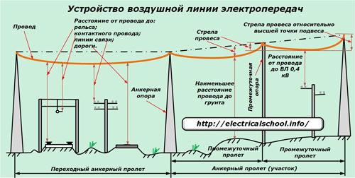
The main elements of air lines are wires, insulators, linear fittings, supports and foundations. On the air lines of the variable three-phase current suspend at least three wires constituting one chain; On DC air lines - at least two wires.
According to the number of chains, the WL is divided into one, two and multi. The number of chains is determined by the power supply scheme and the need for its redundancy. If two chains are required under the power supply scheme, these chains can be suspended on two separate single-chain VLs with single-chain supports or on one two-chained VL with two-charts. The distance / between adjacent supports is called the span, and the distance between the supports of the anchor type is an anchor site.
Wires suspended on insulators (A, - Length of garlands) to supports (Fig. 5.1, a), sag on a chain line. The distance from the point of the suspension to the lower point of the wire is called the arrow of the Prior /. It determines the enabarition of the wire approximation to the Earth A, which is equal to the locality: to the surface of the Earth to 35 and a kV - 7 m; 220 kV - 8 m; to buildings or structures up to 35 kV - 3 m; 110 kV - 4 m; 220 kV - 5 m. The length of the span / is determined by economic conditions. The length of the span to 1 kV is usually 30 ... 75 m; By square - 150 ... 200 m; 220 kV - up to 400 m.
Varieties of power supplements
Depending on the method of suspension of wires, supports are:
- intermediates on which the wires are fixed in supporting clamps;
- anchor type that serve to tension wires; On these tolls, the wires are fixed in stretch clamps;
- angular, which are installed at the angles of rotation of WL with suspension of wires in supporting clamps; They can be intermediate, branches and angular, end, anchor corner.
The same support was enlarged above 1 kV are divided into two types of anchor, fully perceiving the tension of wires and cables in adjacent spans; Intermediate, not perceiving wires or partially perceive.
Wooden supports are used on VL (Fig. 5l, b, B), wooden supports of the new generation (Fig. 5.1, d), steel (Fig. 5.1, e) and reinforced concrete supports.

Wooden supports Vl
Wooden supports are still distributed in countries with forest reserves. The advantages of the tree as a material for the supports are: a small proportion, high mechanical strength, good electrical insulating properties, a natural round sorting. The disadvantage of wood is its rotting, to reduce which antiseptics apply.
The effective method of combating rotting is the impregnation of wood with oil antiseptics. In the US, the transition to wooden glued supports.
For a voltage of 20 and 35 kV, which use pins insulators, it is advisable to use single-suitable candle-shaped supports with a triangular location of the wires. On 6 -35 kV air power transmission with tide insulators at any location of the wires between them D, M, should be no less than the values \u200b\u200bdefined by the formula
where u is lines, kV; - the largest arrow of the provice corresponding to the overall span, m; B is the wall thickness of the ice, mm (no more than 20 mm).
For 35 kV and higher with suspended insulators with horizontal location of the wires, the minimum distance between the wires, M is determined by the formula
Rack of supports are performed by composite: the upper part (actual stand) - from the logs of 6.5 ... 8.5 m long, and the lower part (the so-called stepper) - from reinforced concrete cross section 20 x 20 cm, 4.25 and 6.25 m Or from logs with a length of 4.5 ... 6.5 m. Component supports with reinforced concrete stepmother combine the advantages of reinforced concrete and wooden supports: the grossability and resistance to rotting in the touch of the touch with the soil. The compound of the rack with a stepmaker is performed by wire bands from steel wire with a diameter of 4 ... 6 mm, tensioned with a twist or tension bolt.
Anchor and intermediate angular supports for VL 6 - 10 kV are performed as an aumed structure with composite racks.
Steel power supports
Widely used on voltage voltage of 35 kV and higher.
By constructive performance, steel supports can be two types:
- tower or Single Rooms (see Fig. 5.1, e);
- portal, which, according to the method of consolidation, are divided into freestanding supports and supports on deheating.
The advantage of steel supports is their high strength, disadvantage - corrosion exposure, which requires during the operation of periodic color or anticorrosion coating.
Supports are made of steel angular rolled (mainly applied an equal corner); High transitional supports can be made of steel pipes. In nodes of the connection of the elements, a steel sheet of various thicknesses is used. Regardless of the constructive performance, steel supports are performed in the form of spatial lattice structures.
Reinforced concrete power supports
Compared to metal more durable and economical in operation, as it requires less care and repair (if you take a life cycle, then reinforced concrete - more energy-price). The main advantage of reinforced concrete supports is a decrease in steel consumption by 40 ... 75%, lack of a large mass. By the method of manufacturing, reinforced concrete supports are divided into concrete on the installation site (mostly such supports are used by abroad) and factory manufacture.
Mounting the traverse to the barrel of the reinforced concrete support is performed using bolts skipped through special holes in the rack, or using steel clamps covering the barrel and having a pin for attaching the ends of the traverse belts. Metallic traverses are pre-exposed hot galvanized, so they do not require some time during the operation of special care and observation.
The air lines are performed by uninsulated, consisting of one or more pigged wire. The wires from one wire, called single-rockers (they are made by section from 1 to 10 mm2), have less strength and apply only on a voltage to 1 kV. Multi-voltage wires, retained from several wires are applied on VL of all stresses.
Materials of wires and cables should have high electrical conductivity, have sufficient strength, withstand atmospheric effects (in this respect, copper and bronze wires have the greatest resistance; aluminum wires are subject to corrosion, especially on sea coasts, where salts are contained; steel wires are destroyed even in normal atmospheric conditions).
For VL, one-robust steel wires with a diameter of 3.5 are used; 4 and 5 mm and copper wires with a diameter of up to 10 mm. The limitation of the lower limit is due to the fact that the wires of smaller diameter have insufficient mechanical strength. The upper limit is limited due to the fact that the bends of the single-rocker wire of larger diameter can cause such residual deformations in its external layers, which will reduce its mechanical strength.
Multi-voltage wires twisted from several wires have great flexibility; Such wires can be performed by any cross section (they are made by cross section of 1.0 to 500 mm2).
The diameters of individual wires and their quantity are selected so that the amount of transverse sections of individual wires gave the required overall cross-section of the wire.
As a rule, the multi-voltage wires are made of round wires, and one or more wires of the same diameter are placed in the center. The length of the twisted wire is slightly larger than the length of the wire measured by its axis. This causes an increase in the actual mass of the wire per 1 ... 2% compared to the theoretical mass, which is obtained by multiplying the cross section of the wire for length and density. In all calculations, the actual mass of the wire specified in the relevant standards is taken.
The brands of uninsulated wires indicate:
- letters m, a, ac, ps - material of the wire;
- the numbers are a cross section in square millimeters.
Aluminum wire and maybe:
- aT brands (solid insertion)
- AM (annealed soft) alloys AN, Already;
- ACS, ASCS - from a steel core and aluminum wire;
- PS - from steel wires;
- PST - from steel galvanized wire.
For example, A50 denotes an aluminum wire, the cross section of which is 50 mm2;
- AC50 / 8 is a steel aluminum wire with a cross section of an aluminum part 50 mm2, a steel core of 8 mm2 (the conductivity of only the aluminum part of the wire is taken into account in electrical calculations);
- PSTZ, 5, PST4, PST5 - single-wire steel wires, where the numbers correspond to the wire diameter in millimeters.
Steel cables applied on VL as light-proof, made from galvanized wire; Their cross section should be at least 25 mm2. On the voltage of 35 kV, the cables with a cross section of 35 mm2 are used; on the lines of kV - 50 mm2; On 220 kV lines and above -70 mm2.
The cross-section of the multi-wiring wires of various grades is determined for the voltage of up to 35 kV under the conditions of the mechanical strength, and for the voltage in the KV and higher - under the conditions of losses on the crown. On VL when crossing various engineering structures (communication lines, iron and highways, etc.), it is necessary to ensure higher reliability, so the minimum cross sections of the wires in the intersection spans should be increased (Table 5.2).
When conducting wires by air flow, aimed across the axis of the VL or at a certain angle to this axis, a curvature occurs from the leeward side of the wire. When the frequency of the formation and movement of the vortices with one of the frequencies of its own oscillations, the wire begins to fluctuate in the vertical plane.
Such oscillations of the wire with amplitude 2 ... 35 mm, wavelength 1 ... 20 m and frequency of 5 ... 60 Hz are called vibration.
Usually, the vibration of the wires is observed at a wind speed of 0.6 ... 12.0 m / s;
Steel wires are not allowed in spans over pipelines and railways.

Vibration, as a rule, takes place in flights longer than 120 m and in open areas. The danger of vibration lies in the cliff of individual wire wires in areas of their exit from the clamps of the increase in mechanical voltage. There are variables from periodic bends of wires as a result of vibration and stored in a suspended key main tensile stresses.
In flights up to 120 m long protection against vibration is not required; The protection and sections of any VL protected from transverse winds are not subject to On large transitions of rivers and water spaces requires protection independently of the wires. On the voltage of 35 ... 220 kV and the above, the protection against vibration is performed by installing vibrations suspended on the steel cable absorbing the energy of vibrating wires with a decrease in vibration amplitude near the clamps.
With ice, the so-called dance of the wires is observed, which, as well as vibration, is excited by the wind, but differs from the vibration of a greater amplitude reaching 12 ... 14 m, and a larger wavelength (with one and two half-waves in the span). In the plane perpendicular to the axis of the VL, the wire on the voltage of 35 - 220 kV wires is isolated from the supports of the garlands of suspended insulators. For isolation of VL 6 -35 kV, pin insulators are used.
Passing through the wires VL, it highlights heat and heats the wire. Under the influence of heating the wires occur:
- extension of the wire, increasing the arrows of the Provision, the change in the distance to the Earth;
- changing the tension of the wire and its ability to carry a mechanical load;
- change the resistance of the wire, i.e., change the loss of electrical power and energy.
All conditions may vary if there are constractions of environmental parameters or change together, affecting the operation of the WL wire. When operating, it is believed that at a rated load current, the wire temperature is 60 ... 70 "s. The temperature of the wire will be determined by the simultaneous impact of heat dissipation and cooling or heat sink. The heat sink of wires of the VL increases with increasing wind speed and decrease in ambient temperature.
With a decrease in air temperature from +40 to 40 ° C and increasing wind speed from 1 to 20 m / s thermal losses change from 50 to 1000 W / m. At positive ambient air temperatures (0 ... 40 ° C) and minor wind speeds (1 ... 5 m / s), thermal losses are 75 ... 200 W / m.
To determine the effect of overloading to increase losses, first determined
where Rq is the resistance of the wire at 02, Ohm; R0] - wire resistance at a temperature corresponding to the estimated load under operating conditions, Ohms; A /. ° C - coefficient of temperature increase of resistance, OM / ° C.
An increase in the resistance of the wire compared with the resistance corresponding to the calculated load, possibly when overloading 30% by 12%, and with overload 50% - by 16%
Increase the loss of the losses of overload up to 30%, you can expect:
- when calculating Vl on Au \u003d 5% or? / 30 \u003d 5.6%;
- when calculating Vl on A17 \u003d 10% D? / 30 \u003d 11.2%.
Up to 50% overload, the increase in loss will be equal to 5.8 and 11.6%, respectively. Given the load schedule, it can be noted that when the loss is overloaded up to 50%, the loss briefly exceeds permissible regulatory values \u200b\u200bby 0.8 ... 1.6%, which does not significantly affect the quality of electricity.
Application of SIP wire
Since the beginning of the century, low-voltage air networks are distributed, made as a self-supporting insulated wire system (SIP).
A SIP is used in cities as a mandatory settlement, as a highway in rural areas with a weak population density, branch to consumers. Methods of laying SIP are different: pulling on supports; tensioning by facades of buildings; Laying along the facades.
The design of the SIP (unipolar armored and unarmented, tripolar with an isolated or bare carrier neutral) in general consists of copper or aluminum conductor of a multi-breeding vein, surrounded by an internal semiconductor extruded screen, then insulated with coated polyethylene, polyethylene or PVC. The tightness is provided by a powder and compounded ribbon, on top of which there is a metal screen from copper or aluminum in the form of spirally laid threads or tapes, using extruded lead.
On top of the cable armor, made of paper, PVC, polyethylene, make aluminum armor in the form of a grid of strips and threads. External protection is made of PVC, polyethylene without gelogen. Splings of gaskets, calculated taking into account its temperature and cross-section of wires (at least 25 mm2 for highways and 16 mm2 on branches to inputs for consumers, 10 mm2 for steel aluminum wire) range from 40 to 90 m.
With a slight increase in costs (about 20%) compared to uninsulated wires, the reliability and safety of the line, equipped with a SIP, rises to the level of reliability and safety of cable lines. One of the advantages of air lines with insulated wires was in front of ordinary power transmission lines is to reduce losses and power by reducing reactive resistance. Parameters of direct lines sequence:
- ASB95 - R \u003d 0.31 Ohm / km; X \u003d 0.078 ohm / km;
- SIP495 - respectively 0.33 and 0.078 Ohm / km;
- SIP4120 - 0.26 and 0.078 Ohm / km;
- AC120 - 0.27 and 0.29 Ohm / km.
The effect of loss reduction when using the SIP and the immutability of the load current can be from 9 to 47%, the loss of power is 18%.
Transformers are directly transformed with electricity - a change in the voltage value. Distributing devices are used to receive electricity from transformers (receiving switchgear) and for the distribution of electricity on the consumer side.
In subsequent chapters, the constructive implementation of the main elements of power supply systems is considered, the main types and substation schemes are given, the basis of the mechanical calculation of air lines and tire structures are given.
1. Constructs of electric power lines
1.1. General
Air line(VL) is a device for transmitting electricity over the wires located outdoors and attached with insulators and reinforcements to supports.
In fig. 1.1 shows a fragment of the VL. Distance L between adjacent supports is called the span. The distance vertically between the straight line connecting the suspension points of the wire and the lowest point of its sagging is called arrow Provision Wire Fp . The distance from the lowest point of saving wire to the surface of the Earth is called air line Hg. In the upper part of the supports the threat of protection cable is fixed.
The magnitude of the dimension of the line H g is regulated by Pue, depending on the voltage of the VL and the type of terrain (inhabited, unprofitable, hard to reach). The length of the garlands of insulators λ and the distance between the wires of the adjacent phases H p-p are determined by the rated voltage of the VL. The distance between the high-wire suspension points and the cable h p-T is governed by PUE based on the requirement of reliable protection of the wires of VL from direct lightning strikes.
To ensure the cost-effective and reliable transmission of electricity, conductive materials are needed with high electrical conductivity (low resistance) and high mechanical strength. In the structural elements of power supply systems, copper, aluminum, alloys based on them, steel are used as such materials.
Fig. 1.1. Fragment of the electric transmission
Copper has low resistance and high enough strength. Its specific active resistance ρ \u003d 0.018 Ohm. mm2 / m, and the limit resistance to the gap is 360 MPa. However, it is expensive and scarce metal. Therefore, copper applies, as a rule, to perform transformer windings, less often - for cable veins and is practically not used for air lines.
The resistivity of aluminum is 1.6 times more, the limit resistance to the gap is 2.5 times less than that of copper. The large prevalence of aluminum is in nature and less than that of copper, the cost led to its widespread use for WL wires.
Steel has greater resistance and high mechanical strength. Its specific active resistance ρ \u003d 0.13 ohms. mm2 / m, and the limit resistance to the gap is 540 MPa. Therefore, in power supply systems, steel is used, in particular, to increase the mechanical strength of aluminum wires, the manufacture of supports and light-proof overhead power cables.
1.2. Wires and cables of air lines
The WL wires serve directly to transmit electricity and differ in design and used conductor material. Most economically appropriate
the material for WL wires is aluminum and alloys based on it.
Copper wires for VL are used extremely rarely and with the appropriate feasibility study. Copper wires are used in the contact networks of mobile transport, in networks of special industries (mines, mines), sometimes when the WL passes near the seas and some chemical industries.
Steel wires for VL are not applied, since they have large active resistance and are subject to corrosion. The use of steel wires is justified when performing particularly large spans of WL, for example, when switching through the BL through broad shipping rivers.
The cross sections of the wires correspond to GOST 839-74. The scale of the nominal sections of the WL wires is the following row, mm2:
1,5; 2,5; 4; 6; 10; 16; 25; 35; 50; 70; 95; 120; 150; 185; 240; 300; 400; 500; 600; 700; 800; 1000.
According to the constructive execution of the WL wire: on single-wire;
multi-solid from one metal (monometallic); multi-breeding of two metals; Self-supporting isolated.
Single-wire wiresAs follows from the name, performed from one wire (Fig. 1.2, a). Such wires are made of small sections up to 10 mm2 and are sometimes used for voltage to 1 kV.
Multi-voltage monometallic wires are performed by a cross section of more than 10 mm2 . These wires are made of seweatic wires. Around the central wire, it is observed (row) of six wires of the same diameter (Fig. 1.2, b). Each subsequent obstacle has six wires more than the previous one. The twist of neighboring obes perform in different directions to prevent the wire spinning and giving the wire more round form.
The amount of obesis is determined by the cross section of the wire. The wires with a cross section of up to 95 mm2 are performed with one obey, cross section of 120 ... 300 mm2 - with two overlays, cross-section of 400 mm2 or more - with three and more oblasts. Multi-voltage wires compared to single-line flexible, convenient for installation, reliable in operation.

Fig. 1.2. Constructs of uninsulated wires Vl
To give a wire larger mechanical strength, the multi-voltage wires are manufactured with a steel core 1 (Fig. 1.2, V, G, D). Such wires are called steel aluminum. The core is performed from steel galvanized wire and can be single-wire (Fig. 1.2, c) and a multi-breed (Fig. 1.2, d). The general appearance of a large-aluminum wire of a large cross section with a multi-breed steel core is shown in Fig. 1.2, d.
Steel-aluminum wires are widely used for voltage voltage above 1 kV. These wires are produced in various constructions that differ in the ratio of cross sections of aluminum and steel parts. For conventional steel aluminum wires, this ratio is approximately six, for wires of lightweight design - eight, for wires of a strengthened design - four. When choosing one or another steel aluminum wire, external mechanical loads on the wire such as ice and wind are taken into account.
The wires, depending on the material used, are marked as follows:
M - copper, and - aluminum,
An, already - from aluminum alloys (have a greater mechanical strength than the Wire of the A);
AC - steel aluminum; ASO is a steel aluminum lightweight design;
ACS is a staleluminum reinforced design.
In the digital designation of the wire indicates its nominal cross section. For example, A95 is an aluminum wire with a nominal cross section of 95 mm2. In the designation of steel aluminum wires, the cross section of the steel core can be additionally indicated. For example,

ASO240 / 32 - steel aluminum wire of a lightweight design with a nominal cross section of the aluminum part 240 mm2 and a cross section of a steel core 32 mm2.
Resistant to corrosionaluminum Wires of the ACP brand and steel aluminum wires of ASKP brands, ASSCs, ASK have an inter-level space filled with a neutral lubricant of an increased heat resistance that counteracts the appearance of corrosion. In the Wires of the ACP and ASKP, all the inter-level space is filled with such a lubricant, at the ASSC wire is only a steel core, a steel core is filled with neutral lubricant and is isolated from the aluminum part with two polyethylene ribbons. Wires AKP, ASKP, ASCC, ASK are used for WLs passing near the seas, salted lakes and chemical enterprises.
Self-supporting insulated wires (SIP) apply to voltage to 20 square meters. At stresses up to 1 kV (Fig. 1.3, a), such a wire consists of three phase multi-level aluminum veins 1. The fourth lived 2 is carrier and simultaneously zero. Phase veins are twisted around the carrier in such a way that all the mechanical load is perceived by the carrier residential, made of durable aluminum alloy AVE.
Fig. 1.3. Self-supporting insulated wires
Phase isolation 3 is performed from thermoplastic light-stabilized or cross-stabilized polyethylene. Due to its molecular structure, such insulation has very high thermomechanical properties and high resistance to the effects of solar radiation and atmosphere. In some constructions, the zero carrier vein is performed with isolation.
The design of the SIP for stresses is above 1 kV is shown in Fig. 1.3, b. Such a wire is performed single phase and consists of
councing Steel Aluminum Housings 1 and Insulation 2, made of cross-staple-stabilized polyethylene.
Will with SIP compared to traditional VLs have the following advantages:
less voltage loss (improvement of the quality of electricity), due to the smaller, approximately three times, the reactive resistance of three-phase SIP;
do not require insulators; practically no ice-based formation;
allow suspension on one support of several lines of different voltages;
smaller operating costs, due to the reduction, approximately 80%, the volume of emergency and restoration work; Ability to use shorter supports thanks
a smaller permissible distance from SIP to the Earth; Reducing the security zone, permissible distances to buildings and
structures, widths of seekers in a wooded area; The practical absence of the possibility of fire in
woodland during the fall of the wire on the Earth; High reliability (5-fold reduction in the number of accidents
compared with traditional VL); Full protection of the conductor from moisture exposure and
corrosion.
The cost of HL with self-supporting insulated wires is higher than traditional ll.
Wires of 35 kV voltage and above are protected from direct lightning strike ground-proof cablefixed in the upper part of the support (see Fig. 1.1). Ground-proof cables are elements of VL, similar in their design by multi-breed monometallic wires. Cables are performed from steel galvanized wires. The rated cable cross sections correspond to the scale of the nominal sections of the wires. The minimum cross section of the outflowing cable is 35 mm2.
When using lightning protection cables as high-frequency communication channels instead of steel cable, a steel-aluminum wire with a powerful steel core is used, a cross section is commensurate or more of the cross section of the aluminum part.
1.3. Supports of air lines
The main purpose of the supports is the support of the wires at the required height above the ground and land facilities. Supports consist of vertical racks, traverse and foundations. The main materials from which supports are manufactured are wood coniferous rocks, reinforced concrete and metal.
Wood supportssimple in manufacturing, transportation and operation, are used for voltage to 220 kV inclusive in areas of forestry or close to them. The main disadvantage of such supports is wood exposure to winding. To increase the service life of supports, wood dry and impregnate with antiseptics that impede the development of the rotation process.
Due to the limited construction length of wood, the supports are performed by composite (Fig. 1.4, a). Wooden stand 1 is articulated with metal bands 2 with reinforced concrete prefix 3. The bottom of the console is plunged into the ground. Supports corresponding to rice. 1.4, and, apply to voltage up to 10 kV inclusive. At higher stresses of wood supports are performed by P-shaped (portal). Such a support is shown in Fig. 1.4, b.
It should be noted that in modern conditions for the need to preserve forests, it is advisable to reduce the use of supports from wood.
Reinforced concrete supportsconsist of reinforced concrete rack 1 and traverse 2 (Fig. 1.4, B). The rack is a hollow cone tube with a small inclination of the forming cone. The lower part of the rack is plugged in the ground. Traverts are made of steel galvanized rental. These supports are longer than wood supports, easy to maintain, require less metal than steel supports.
The main disadvantages of supports from reinforced concrete: a high weight that makes it difficult to transport the supports into the hard-to-reach places of the VL route, and the relatively small strength of the bending concrete.
To increase the strength of the bending supports in the manufacture of reinforced concrete rack, a pre-tense (stretched) steel fittings is used.
To ensure high concrete density in the manufacture of supports supports vibration removal and centrifugationconcrete.

The stands of the rolling supports of up to 35 kV are performed from the vibrobeton, at higher voltages - from centrifuged concrete.
Fig. 1.4. Intermediate supports VL
Steel supports have high mechanical strength and a long service life. These supports with welding and bolt compounds are collected from individual elements, so it is possible to create a support of almost any design (Fig. 1.4, d). In contrast to the supports of wood and reinforced concrete metal supports are installed on reinforced concrete foundations 1.
Steel supports are expensive. In addition, steel is subject to corrosion. To increase the service life of the supports, they are covered with anti-corrosion compositions and paint. Very effective against corrosion is hot galvanizing steel supports.
Aluminum alloys supports effective when building VL in conditions of hard-to-reach tracks. Due to the resistance of aluminum to corrosion, these supports do not need an anti-corrosion coating. However, the high cost of aluminum significantly limits the possibilities of using such supports.
When passing on a certain territory, the airline can change the direction, cross various engineering

constructions and natural barriers, connect to tires for distribution devices substations. In fig. 1.5 shows the top view of the fragment of the ll route. From this picture it is clear that different supports work in different conditions and, therefore, should have a different design. According to constructive execution, supports are divided:
to intermediate(Supports 2, 3, 7), installed on the direct plot of VL;
corner (support 4), installed on the turns of the voltage of the VL; terminal (supports 1 and 8), installed at the beginning and end of the ll; Transition (supports 5 and 6) installed in the span
crossing the airliner of any engineering structure, such as the railway.
Fig. 1.5. Fragment of the highway VL
Intermediate supports are designed to maintain wires on the direct plot of VL. The wires with these supports do not have a hard compound, as they are attached with the help of supporting insulant garlands. These supports are the forces of gravity of wires, cables, insulators garlands, ice, as well as wind loads. Examples of intermediate supports are shown in Fig. 1.4.
On the end supports additionally affects the power of tons of wires and cables, directed along the line (Fig. 1.5). The angular supports additionally affect the power of tons of wires and cables, directed along the bisector of the angle of rotation of the VL.
Transitional supports in normal mode VL perform the role of intermediate supports. These supports take on the charges of wires and cables when they are climbing in neighboring spans and exclude invalid sagging of wires in the intersection span.
End, angular and transitional supports must be rigid enough and should not deviate from the vertical

provisions when exposed to the forces of the forces of wires and cables. Such supports are performed in the form of hard spatial farms or using special cable stretch marks and are called anchor supports. The wires with anchor supports have a rigid connection, as they are attached with the help of tensioning garlands of insulators.
Fig. 1.6. Anchor corner supports
Wood anchor supports are performed by A-shaped at voltages to 10 kV and up-shaped at higher voltages. Reinforced concrete anchor supports have special cable stretch marks (Fig. 1.6, a). Metal anchor supports have a wider database (lower part) than intermediate supports (Fig. 1.6, b).
By the number of wires suspended on one support, distinguish disposal and two-chained supports. Three wires (one three-phase chain) are suspended on single-chain supports, on two-charts - six wires (two three-phase chains). Disposal supports are shown in Fig. 1.4, a, b, g and rice. 1.6, and; Two-charts - in Fig. 1.4, B and Fig. 1.6, b.
Two-chain support compared to two monolators is cheaper. The reliability of electricity transmission over a two-chart line is slightly lower than in two single-chain.

Wood supports in two-charts are not manufactured. Supports voltage of 330 kV and above are manufactured only in a single-chain version with a horizontal location of the wires (Fig. 1.7). Such supports are manufactured by P-shaped (portal) or V-shaped with cable stretch marks.
Fig. 1.7. Supports voltage 330 kV and above
Among the supports of the ll separately, supports having special design.These are branches, elevated and transposition supports. Distributor supports are designed for intermediate power take-off from VL. Increased supports are installed in large spans, for example, when moving through broad shipping rivers. On the transpositivesupports carried out transposition of wires.
The asymmetrical location of the wires on the supports with a high length of the VL leads to the voltage asymmetry of the phases. Symmetry of the phases due to changes in the mutual location of the wires on the support is called transposition. The transposition is provided for an 110 kV voltage and higher than 100 km longer and is carried out on special transposition supports. The wire of each phase passes the first third of the length of the VL on one, the second third - on the other and third - in third place. Such movement of wires is called a full transposition cycle
Sophisticated power lines (LPP), serve to deliver electricity over long distances. On the scale of the state, they are strategically important objects that are designed and erected in accordance with SNiP and Pue.
These linear sections are classified on cable and air power transmission lines, installation and gasket of which require compulsory compliance with the calculated conditions and the installation of special designs.
Air lines power lines
Fig.1 Air high-voltage power lines
The most common is the air lines, the laying of which occurs in the open air using high-voltage pillars, to which the wires are fixed using special fittings (insulators and brackets). Most often is the racks of the SC.
The power of power supply includes:
- supports for different stresses;
- bare wires of aluminum or copper;
- traverses that ensure the required distance, eliminating the possibility of contacting wires with elements of support;
- insulators;
- ground contour;
- dischargers and Lightning Course.
The minimum wisp should be: 5 ÷ 7 meters in non-heated terrain and 6 ÷ 8 meters in settlements.
As high-voltage columns are used:
- metal structures that are effectively used in any climatic zones and with different loads. They are distinguished by sufficient strength, reliability and durability. Represent a metal frame, the elements of which are connected using bolted connections that facilitate the delivery and installation of the supports on the installation site;
- reinforced concrete supports, which are the easiest view of the structures that have good strength characteristics, are easy to install and install on them. The disadvantages of the installation of concrete supports include - a certain effect on them of wind loads and the characteristics of the soils;
- wooden supports that are the most low-cost in production and have excellent dielectric characteristics. The small weight of the wood structures allows you to quickly deliver them to the place of installation and easy to install. The disadvantage of these PSP supports are low mechanical strength, which allows them to be installed only with a certain load and exposure to biological destruction processes (material rotting).
The use of one or another design is caused by the voltage of the electrical network. We use the skill to determine the power supply voltage in appearance.
Classified ll:
- by current - permanent or variable;
- upon voltage rates - for direct current with a voltage of 400 kilovolts and variable - 0.4 ÷ 1150 kilovolt.
Cable LP.

Fig.2 Cable lines underground type
Unlike air lines, cable are insulated and therefore they are more expensive and reliable. This type of wires are used in places where the installation of air lines is impossible - in cities and settlements with dense development, in the territories of industrial enterprises.
Cable LP Classified:
- on voltage - just like the air lines;
- by type of insulation - liquid and solid. The first type is petroleum oil, and the second is a cable braid consisting of polymers, rubber and wash paper.
The distinctive features are the laying method:
- underground;
- underwater;
- for structures that protect cables from atmospheric influences and provide a high degree of safety during operation.

Fig.3 Laying underwater power lines
Unlike the first two ways of laying cable power passes, the option "Construction" provides for the creation:
- cable tunnels in which power cables are placed on special support structures, allowing installation work and maintenance of lines;
- cable channels that are swallowed structures under the floor of the buildings in which the laying of cable lines occurs in the ground;
- cable mines - vertical corridors having a rectangular cross section that provide access to power transmission;
- cable floors, which are dry, technical space with a height of about 1.8 m;
- cable blocks consisting of pipes and wells;
- open type Overap - for horizontal or inclined cable gasket;
- cameras used to lay connective couplings of LPP sites;
- gallery is the same overpass, only a closed type.
Conclusion
Despite the fact that cable and power lines are used everywhere, both options have their own characteristics that must be taken into account in the design documentation defining
Transportation of electrical energy on medium and long distances is most often produced by power lines located outdoors. Their design should always meet two basic requirements:
1. reliability of transmission of high capacity;
2. Security for people, animals and equipment.
When operating under the influence of various natural phenomena associated with hurricane wind gusts, by deposit, the fallout of the power lines are periodically exposed to increased mechanical loads.
For a comprehensive solution of the tasks of safe transportation of electrical power facilities, energy has been raising wires that are under high height, spread them in space, isolate from building elements and mounted clock-in sections on high-strength supports.
General Device and Layout of Air LP

Schematically, any electricity transmission line can be submitted:
supports installed in the soil;
wires for which the current is passed;
linear reinforcement mounted on supports;
insulants, fixed on fittings and holding orientation of wires in airspace.
Additionally, the elements of the VL must be attributed:
foundations for supports;
system of lightning protection;
ground devices.
Supports are:
1. Anchor, intended to withstand the efforts of stretched wires and equipped with tension devices on the reinforcement;
2. Intermediates used to secure wires through supporting clamps.
The distance on the soil between two anchor supports is called an anchor area or a span, and at intermediate supports between themselves or with anchor-intermediate.
When the air power transmission lines passes over water barriers, engineering structures or other responsible objects, at the ends of such a plot, supports are installed with tensioning wires of wires, and the distance between them is called an intermediate anchor span.
Wires between supports never stretch as a string - in a straight line. They always sag a little, located in the air, taking into account climatic conditions. But at the same time, the safety of their distance to ground objects is taken into account:
surfaces of rails;
contact wires;
transport highways;
lines of communication lines or other VL;
industrial and other objects.
Schedule the wires from the stretched state are called. It is estimated in different ways between supports because the upper parts may be located at one level or with exceeding.
Street Provision relative to the highest point of the support is always more than the bottom.
The dimensions, length and design of each type of air power transmission depend on the type of current (variable or permanent) electrical energy transported by it and its voltage value, which can be less than 0.4 kV or reach 1150 kV.
Airline lines
Since the electric current passes only by a closed contour, then the power supply of consumers is performed at least two conductors. By this principle, simple air power transmission lines of single-phase alternating current with a voltage of 220 volts are created. More complex electrical circuits transmit energy over three or four-wire diagrams with deafly isolated or grounded zero.
The diameter and metal for the wire are selected under the design load of each line. The most common materials are aluminum and steel. They can be performed by a single monolithic residential for low-voltage schemes or gossip from multi-level structures for high-voltage power transmission lines.
The inner inter-spite space can be filled with a neutral lubricant that increases the resistance to heating or be without it.
Multi-level structures made of aluminum wires, well-transmitted currents, are created with steel cores, which are designed to perceive mechanical tension loads, prevent breaks.

GOST is given a classification of open wires for air power transmission lines and their marking is defined: M, A, AC, PSO, PS, ACKC, ASKP, ACS, ACO, ASUS. In this case, single-wire wires are denoted by diameter value. For example, the reduction in PSO-5 is read "Steel wire. Completed by one residential with a diameter of 5mm. " The multicore wires for the LAP use another marking, which includes the designation with two digits recorded through the fraction:
the first is the total area of \u200b\u200bthe cross section of aluminum lived in MM KV;
the second is the cross-sectional area of \u200b\u200bthe steel insert (MM KV).
In addition to open metal conductors, the wires are increasingly used in modern airlines:
self-supporting isolated;
protected by an extruded polymer that protects against the occurrence of KZ during the winding phases by the wind or the accuracy of foreign objects from the ground.
Air lines with gradually displacing old uninsulated structures. They are increasingly used in internal networks, made from copper or aluminum veins coated with rubber with a protective layer of dielectric fibrous materials or polychlorvinyl plastics without additional external protection.

To eliminate the emergence of the corona discharge of a large length of the wire of the VL-330 kV and the highest voltage, split into additional streams.

On VL-330, two wires are mounted horizontally, in line 500 kV they increase to three and placed on the vertices of the equilateral triangle. For VL 750 and 1150 kV, splitting on 4, 5 or 8 flows, respectively, located along the corners of their own equilateral polygons are used.
The formation of "crown" leads not only to the loss of electricity, but also distorts the form of sinusoidal oscillation. Therefore, it is struggling with design methods.
Support support
Usually supports are created to fix the wires of one electrical circuit. But one common support can be used on the parallel sections of two lines, which is designed for their joint installation. Such structures are called two-charts.

Material for the manufacture of supports can be:
1. Profiled corners from various steel grades;
2. Building wood logs impregnated with preparations from posting;
3. Reinforced concrete structures with reinforced rods.
Supported structures made from wood are the cheapest, but even with good impregnation and proper service serve no more than 50 ÷ 60 years.

According to the technical execution, the support of the VL above is 1 kV differ from low-voltage with its complexity and high fastening height.

They are made in the form of extended prisms or cones with a wide base below.
Any design of the support is calculated on mechanical strength and stability, has a sufficient design reserve to the current loads. But it should be borne in mind that during operation there are disturbances of various elements as a result of corrosion, shocks, non-compliance with installation technology.
This leads to a weakening of the rigidity of a single design, deformations, and sometimes both downs. Often such cases occur in those moments when people work on supports, performing dismantling or tension of wires, creating variable axial efforts.
For this reason, the admission of the brigade of the Monterters to work at the height with the design of the supports is carried out after checking their technical condition with an assessment of the quality of its bellped part in the soil.
Device of insulators
On the air power transmission unit for separating the current-generating parts of the electrical circuit, and from the mechanical elements of the structures of the supports are used by materials from materials with high dielectric properties with ÷ ohm. They are called insulators and manufactured from:
porcelain (ceramics);
glass;
polymeric materials.

Constructions and dimensions of insulators depend:
from the values \u200b\u200bof the dynamic and static loads attached to them;
values \u200b\u200bof the current voltage of the electrical installation;
operating conditions.
The complicated surface shape, working under the influence of various atmospheric phenomena, creates an increased path for the flow of a possible electrical discharge.
Insulators installed on air lines for fastening wires are divided into two groups:
1. Pins;
2. Suspended.
Ceramic models
Porcelain or ceramic pin single insulators have found more use on VL to 1 kV, although they work on lines up to 35 kV inclusive. But they are used in the condition of fastening the wires of low sections, creating small traction efforts.
Garlands from suspended porcelain insulators are installed on lines from 35 square meters.

The kit of a single porcelain suspended isolator includes a dielectric housing and a hat, which is added from the forging cast iron. Both of these details are fasten with a special steel rod. The total number of such elements in the garland is determined by:
the magnitude of the voltage ll;
support structures;
features of equipment operation.
With an increase in the line voltage, the number of insulators in the garland is added. For example, for 35 kV 33 kV, it is enough to install 2 or 3, and 110 kV - 6 ÷ 7 will be required.
Glass insulators
These structures have a number of advantages over porcelain:
the lack of internal defects of insulating material affecting the formation of leakage currents;
increased strength to twisting efforts;
transparency of the structure that allows you to visually evaluate the state and perform control the angle of polarization of the light flux;
lack of signs of aging;
automation of production and smelting.
The disadvantages of glass insulators are:
weak anti-vandal stability;
low strength to the effect of shock loads;
the possibility of damage during transportation and installation from mechanical effort.
Polymer insulators
They have increased mechanical strength and reduced to 90% weight compared to ceramic and glass analogues. Additional advantages include:
ease of installation;
high resistance to contamination from the atmosphere, which, however, does not exclude the need to periodically clean their surface;
hydrophobicity;
good perception of overvoltages;
increased vandalustability.
The durability of polymeric materials also depends on the operating conditions. In an air environment with elevated pollution from industrial enterprises, polymers may appear the phenomena of the "fragile breakdown", which consist in the gradual change in the properties of the internal structure under the influence of chemical reactions from pollutants and atmospheric moisture flowing in the complex with electrical processes.
When executing vandals of insulators from a polymer with a fraction or bullets, it usually does not happen to complete material destruction, like glass. Most often, the crusher or bullet flies the wave or stuck in the skirt housing. But the dielectric properties are still undesirable and damaged elements in the garland require replacement.
Therefore, such equipment must be periodically examined by visual control methods. And it is almost impossible to identify such damage without optical devices.
Armature of air lines
For fastening the insulators on the support of the WL, the assembly of them in the garland and the installation of the conductive wires are available special fasteners that are called the line fittings.

According to the tasks performed, the reinforcement is classified into the following groups:
coupling intended for connecting suspended elements in various ways;
stretched, serving for fastening tension clamps to wires and garlands of anchor supports;
supporting, carrying out the hold of fixtures of wires, loops and editing nodes of screens;
protective, intended to preserve the performance of equipment of the WL when exposed to atmospheric discharges and mechanical oscillations;
connective consisting of oval connectors and thermal cartridges;
contact;
spiral;
installation of pin insulators;
installation of cip wires.
Each of the listed groups has a wide range of parts and requires more close study. For example, only protective reinforcement includes:
protective horns;
rings and screens;
arresters;
vibration dampers.
Protective horns create a spark gap, remove the appearing electrical arc when the insulation overlap occurs and the equipment should be protected in such a way.
Rings and screens remove the arc from the surface of the insulator, improve the distribution of the voltage over the entire area of \u200b\u200bthe garland.
The arresters protect equipment from overvoltage waves arising from lightning strike. They can be used on the basis of tubular structures from veniplast or fibrobelite tubes with electrodes or be made by valve elements.

Vibration dampers work on cables and wires, prevent damage from fatigue stresses created by vibrations and oscillations.
Grounding devices of air lines
The need to re-ground the ownership of the WL is caused by the requirements of safe operation in the event of emergency regimes and thunderstorm overvoltages. The impedance of the circuit of the grounding device should not exceed 30 ohms.
At metal supports, all fasteners and fittings must join the PEN conductor, and the reinforced concrete zero associates all the struts and fittings of the racks.
On the supports made of wood, metal and reinforced concrete pins and hooks when mounting a sip with a carrier insulated conductor are not ground, except in cases of the need to perform repeated grounds for overvoltage protection.

The hooks and pins mounted on the support are connected to the storage circuit with welding using steel wire or bar not thinner than 6 mm in diameter with the mandatory presence of an anti-corrosion coating.
Metal fittings apply on reinforced concrete supports for grounding descent. All contact compounds of grounding conductors are welded or clamping in a special bolt mount.
Supports of electric power lines with a voltage of 330 kV and above are not ground due to the complexity of the implementation of technical solutions to ensure the safe size of the tap and step. Protective grounding functions in this case are assigned to high-speed line protection.
 Why you can not give icons
 Is it possible to give icons as a gift: Signs, the opinion of the Church
 A year ago left her husband, and now I do not know what to do