Connecting an RGB LED strip with your own hands. Installation and connection of a controller for an LED strip with a remote control Connection diagram for an LED strip with a controller and amplifier
Modern technical innovations open up new opportunities for creating interesting design solutions in your own home, in stores, in enterprises, etc. A new milestone in enhancing contour lines is LED strips, which are installed to illuminate ceilings, signs, furniture and other elements. In comparison with the classic white LED strip, installing a multi-colored one seems to be a relatively complicated process for many ordinary people. Therefore, now we will analyze the features of connecting an RGB strip and choosing components for its full operation.
Required Items
The abbreviation RGB means the three main colors of the diodes used to obtain the gamma:
- R – means red (in English red);
- G – means green (in the English version green);
- B – stands for blue (blue in English).
A crystal is responsible for each color, for the power supply of which its own track is supplied, because of this, 4 or 5 wires are used to power multi-color RGB strips.
Rice. 1: example of powering RGB strip crystals
Therefore, full power supply of the lighting source requires the installation of additional equipment that converts the parameters of electric current and voltage from the network.
RGB controller
This block is designed to separate an electrical signal into three or four colors. The number of controller outputs is selected depending on the tape parameters. The RGB controller allows you to control the color or shade of the glow. Based on the control method, they are divided into wired and wireless. The last option is the most convenient and popular; it can be controlled by:
- WiFi– controlled both from a standard remote control and using a mobile application that is linked to the controller via a gadget;
- Infrared input– the controller in such devices must be located in the field of view so that the beam from the remote control can be directed in its direction;
- Radio channel– controlled via radio signal, in this case you can switch LED devices from anywhere in the house.
When connecting to the control unit, it is important to observe the color coding of the terminals:
 Rice. 2: Controller terminal markings
 power unit
Due to the fact that multi-color diode strips do not use standard power from the electrical network, but a lower voltage level, you will need. To supply power to RGB tapes, a voltage of 12 V is used, and in some situations a nominal value of 24 V can be used. Depending on the type of tape selected, the output voltage of the unit is also selected.
The second determining parameter for a power supply is the nominal power, which is also determined in accordance with the power of the RGB LED strip. As a rule, power is indicated per linear meter. For example, you have a strip with a power of 15 W/m, respectively, to power a strip 5 m long you will need 15 × 5 = 75 W. In addition, it is necessary to make a power reserve of 20 - 30%, that is, (75 × 30)/100 = 22.5 W, so the resulting power must be at least 75 + 22.5 = 97.5 W, you can take a model for 100 W, and in the absence of one, 120 W.
In addition, power supplies for RGB strips differ in the degree of protection from external factors. For bedrooms, halls, hallways, the degree of resistance to moisture and dust IP20 will be sufficient. For rooms with high humidity, for example, baths, kitchens, laundry rooms, it is necessary to use models with a degree of IP67 or IP69. When connecting, be sure to follow the order of connecting the terminals
 Rice. 3: location of power supply terminals
 RGB tape
This is a flexible design with LED modules located on it. Each of the RGB strip modules in the standard version contains three crystals (one each for blue, red and green glow colors). To power such a strip, four pins are used, of which three are used to supply a color signal, and the fourth is a common plus. The disadvantage of such strips is the lack of a pure white glow from LEDs, since the result obtained from combining three primary colors differs significantly from classic monochrome models.
But for everyone who wants to get a pure white glow, LED RGB strips with four crystals in each block come to the rescue. They received the RGB W marking, since the fourth crystal produces pure white color. Due to the presence of an additional crystal, power is supplied via a five-wire system. Accordingly, controllers with five pins are used to supply power to such RGB strips.
It should be noted that when choosing an RGB strip, it is preferable to use models assembled from newer SMD 5050 LEDs, since they are capable of changing the color glow of the crystal, unlike the older versions of SMD 2835 and SMD 3528, in which each crystal glowed in one color.
Amplifier
An RGB amplifier is used to power strips longer than 5m, where due to power loss and voltage drop, the brightness of the glow will be significantly reduced. The standard length of one coil may not be enough to illuminate the perimeter you need, so you will have to use several coils or add a piece of tape. The signal amplifier is designed to increase the supply voltage and provide an additional power limit.
The amplifier is selected according to the power of the section exceeding 5 m of total length. If the total length contains several sections of 5 m, then after the first, each of them requires its own amplifier. If the power supply unit has sufficient power, the amplifier can be powered from the same unit as the first section of the tape. If this is not enough, then each amplifier must be connected to a separate unit.
If the space to place the amplifier is limited (a niche in a box, a distribution box, etc.), you can use a microamplifier. It is significantly smaller than standard devices, but allows you to perform the same functions.
Connection principle
To mount a working system with RGB tape, you must perform the following steps:

Connection diagrams
Depending on the length of the RGB tape, different equipment is used and the order in which it is turned on changes. To better understand the principle of constructing an electrical circuit, you can familiarize yourself with ready-made options for their implementation in your own projects.
With amplifier
It should be noted that the amplifier does not affect the brightness of the glow, so it makes no sense to use it for RGB strips up to 5 m long. Installation of an amplifier is justified only in situations where the total length exceeds 5 m. Depending on the power of the sections, the amplifier can be powered from the same power supply as the controller or from a separate one.
 Rice. 7: circuit with one power supply
  Rice. 8: circuit with two power supplies
 This diagram shows a parallel connection of power supplies to RGB strips connected through an amplifier.
Without amplifier
If there is a need to connect a strip longer than 5 m, they can be powered without using an amplifier. But at the same time, it is necessary to install both a separate power supply and a controller for each section up to 5 m long.
 Rice. 9: tape power without amplifier
 Look at Figure 9, this circuit has a separate power supply for each RGB strip, thereby ensuring autonomy for each of them. But the disadvantages of this scheme include controlling the color scheme and the operation of the backlight with a separate remote control for each area.
With controller
The simplest power supply scheme for an RGB strip is with one power supply and one controller.
 Rice. 10: power circuit with controller
 Look at Figure 10 - this is the simplest option that allows you to connect an RGB strip with full working functionality. Its only drawback is that it can only power a strip up to 5 m.
Without controller
It should be noted that an RGB strip without a controller cannot fully function, since without this device it is impossible to switch colors. But, as a temporary option, while replacing a failed controller, this connection diagram can be used.
 Rice. 11. Power circuit without controller
 Look at Figure 11, you need to connect the common wire from the tape to the positive terminal of the power supply, and solder the colored wires together in a parallel connection and connect to the negative terminal of the unit. But the entire RGB strip will light up in only one color.
Frequent connection errors
Despite the simplicity of the above work, mistakes are often made during connection that can ruin all your efforts. Therefore, it is worth paying attention to them:
- The connection is made in strict sequence - power supply - connector - RGB strip - (amplifier) - RGB strip.
- When peeling off the film on budget models, factory soldered contacts are often exposed, which, when mounted on a conductive surface, can burn out from load currents;
- When combining several sections of tape, their connection should be made using special connectors or soldering, but never by twisting;
- The cross-section of the wires for connection should be selected in accordance with the load, otherwise they may burn out;
- The power of the power supply cannot be chosen back to back; it is necessary to provide a reserve;
- High power LED strips must be installed with a heat sink;
- Serial connection of more than 5 m of RGB strip should be made only through an amplifier or from a separate power supply and controller.
Video to help
In recent years, along with traditional light sources (incandescent lamps, fluorescent lamps), lighting devices based on high-brightness light-emitting diodes (LEDs) have become widely used. The compact size of LEDs and their low power consumption make it possible to create light sources with new properties. For example, LED strips are widely used to illuminate shop windows and billboards, and to organize designer lighting for apartment interiors. One such type is RGB LED strip.
RGB technology
The physical principles of LED operation do not allow direct production of “white” light. However, scientists managed to get around this limitation. To produce white light, phosphor LEDs were invented, in which the “white light” is emitted by a special coating applied to a blue, super-bright LED.
Another way to produce white light is to use three LEDs: red, green and blue. A cell of three LEDs emits light of three colors, which is perceived by humans as white. This method of producing “white” light is called RGB technology. This abbreviation is made up of the first letters of the English names of colors (Red, Green, Blue).
By adjusting the brightness of LEDs, you can get not only white light, but also many colors and shades. The number of shades can reach hundreds of thousands. Therefore, RGB LED strips have significantly greater capabilities than phosphor LED strips.
Device
LED RGB strip is a flexible printed circuit board on which LEDs and resistors are placed that limit the diode current. The width can vary from 8 to 20 mm. There are strips on which LEDs of different colors are placed next to each other. However, the most widespread are LED strips with LEDs assembled in one housing. This RGB LED has six pins.
LEDs come in several sizes. The most common LEDs are LED-RGB-SMD 5050, 5x5 mm in size. A linear meter of LED strip can accommodate 30 or 60 LEDs (double density). Depending on the number of LEDs and their standard size, the power consumption and luminous flux depend.

For fastening to various surfaces, double tape is glued to the back of the RGB LED strips. LED strips are available with different degrees of protection (IP). Products with a low degree of protection can only be used in dry rooms. Silicone-coated tapes are not afraid of direct moisture and can even be immersed in water (IP68).
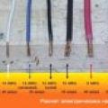
The standard length of LED RGB strip is 5 meters. However, it can be of different lengths. Manufacturers mark the places where cuts can be made with a dotted line and a “scissors” symbol. At the cut sites there are contact pads to which power is connected. The purpose of the contact pads is marked with the letters R, G, B and a plus sign.
Connection
To power and control the LED strip, a power supply and a specialized controller are required. The power of the power supply and controller must match the power consumed by the RGB strip. It is better if their capacities are selected with a small margin.
The connection diagram is quite simple. The 12V (24V) output of the power supply is connected to the corresponding terminals of the controller, observing polarity. Control voltages from the controller are supplied to the LED strip. In this case, it is also necessary to ensure that the conductors are connected correctly: R to R, G to G, and so on.

It is better to make connections between the power supply and the controller using a two-wire cable, and between the controller and the tape - a four-wire cable. The cross-section of the cable core should not be less than 0.25 mm 2. You can connect conductors to sections of LED strip using soldering, but it is better to use special connectors and cables. You can read more about the connection.
Controller for RGB strip
Microprocessor controllers for RGB strips allow you to adjust the color and brightness of lighting and create various lighting effects. According to the control method they are distinguished:
- Controllers with IR control;
- Controllers controlled via radio channel.
- Controllers controlled via Wi-Fi.

In the first two cases, the controller is controlled using a remote control. Only the methods of transmitting control signals differ - infrared rays or radio waves. Control via Wi-Fi can be carried out from a laptop, tablet, smartphone or other devices. The Wi-Fi protocol, software, controller and multi-colored LED strip can create many interesting lighting effects.
You cannot connect more than one LED strip to one controller. It may not be able to withstand the load! If you need to connect several, you need to use a special amplifier.
Amplifier for RGB strip
The purpose of the amplifier is in many ways similar to the purpose of the controller. It repeats the controller control signals at its outputs. Just like the controller, it is connected to the power supply. The connection diagram for several tapes is shown in the figure.

Connection diagram via amplifier

Amplifier
Video
Summing up
By using RGB LED strips for lighting, you can create a cozy atmosphere in your home (for example, make one), save a lot of energy, and forget about replacing light bulbs for decades.
» Connection diagram for multi-color tapeConnection diagram for LED RGB strip. Connecting an RGB controller and an RGB amplifier.
I described in detail what a multicolor LED RGB strip is in this article. Now, I'll tell you about electrical connection diagram.
In principle, the connection diagram for an RGB tape is the same as the connection diagram for a regular one-color (monochrome) tape. The difference is that between the power supply and the tape, it is installed RGB controller(tape color control device).
Controllers vary in appearance, power, color management programs and remote control. But the essence of them all is the same. The controller received 2 wires from the power supply, four wires went to the RGB strip.
Connection diagram for RGB controller for LED strip
Whatever controller you choose, it is always connected according to the same circuit. Connectors and power supply are designated “ V+" And " V-" Accordingly, the red wire of the power supply goes to the positive contact, and the black wire goes to the negative one.
Connectors for connecting RGB strips are designated:
- R(red)- red color control
- G (green)- green color control
- B (blue)- blue color control
- V+ common wire (it may be designated differently on different controllers, but you still won’t confuse it with others)
Do not mix up the tape wires! Nothing bad will happen, of course (nothing will burn), but your colors will be mixed up. Press red on the remote control and blue will light up.

RGB strip control panel: whichever button you press, it will glow that color
How to connect more than 5 meters of tape? The current-carrying paths of the LED strip are designed for a length of 5 meters (which is why the strip is always sold in this length). You can’t just take and connect two tapes in series. Even if it works, it will not last long (tested in practice).
The principle of elongation is the same as with regular tape. There are two ways. Here's the first one

Connection diagram for RGB strips with one power supply
This circuit requires a four-core extension wire with a cross-section of 1.5 mm and a length of 5 meters. I use this circuit to connect RGB strips with 30 diodes per meter. But because This strip shines dimly (due to the small number of LEDs) and there are few people who want to use it, so I rarely use this circuit.
With RGB strips of 60 diodes per meter, you can also use this scheme, but at the same time, you will need a power supply and a controller with 2 times more power.
Let's do the math. Two RGB strips consume 140 watts. A power supply of such power is a heavy piece of iron, of quite considerable size. Of course, you can hide it in a ceiling niche. But for this, it is necessary to plan a place for it in advance (at the ceiling design stage).
140 watt controller. As my experiences show, controllers fail after a while. Although the technical parameters indicate that they are designed for such power and pull 10-15 meters. In fact, they are burning. I have already had several cases, although according to calculations, everything seems to be working.
Therefore, I recommend choosing a controller with a power reserve of 2 times, i.e. for this case, it is 280 watts. But here, its cost increases sharply, and it’s not easy to find which controller. Therefore, I like this scheme better

Connection diagram of LED RGB strips using an RGB amplifier
In this connection diagram, an additional power supply is used and RGB amplifier.The end of the first tape is connected to the input of the amplifier (it says “Input”), and the beginning of the second tape is connected to the output (it says “Output”).
Do not confuse the colors of the wires: each wire is connected to the corresponding connector. Connect the wires from the power supply to the power contacts.

Connecting an RGB amplifier
This scheme is a little more complicated and the cost is a little more expensive than the first one, but at the same time:
- Power supply sizes are significantly smaller
- Almost all commercially available controllers can be used
- You can connect an unlimited number of tapes
If you find it difficult to understand electrical circuits, then here is a photo that shows everything. Again. If you need one tape, then use a power supply and a controller. If you need two or more tapes, then add an amplifier and another power supply.
- Incorrect installation and connection with errors
Here are the main three rules and mistakes that you need to pay attention to first.
1 rule

The LED strip is connected in parallel, in sections of no more than 5 meters each.
It is even sold in reels of this meter. What if you need to connect 10 or 15m? It would seem that you connect the end of the first piece with the beginning of the second and you're done. However, such connection is prohibited. Why is this so accepted?
Because five meters is the estimated length that the current-carrying tracks of the tape can withstand. With a longer length, the load will exceed the permissible one and the tape will definitely fail. In addition, uneven glow will be observed. At the beginning of the strip, the LEDs will shine brightly, and at the end they will be much dimmer.
This is what a parallel connection diagram for LED strips with a length exceeding the permissible length will look like: 
In this case, the tape can be connected both from two sides and from one. Connecting on both sides allows you to reduce the load on the current paths, and also helps to avoid uneven glow at the beginning and end of the tape. 
This is especially important on a powerful tape - over 9.6 W/meter. This is exactly how professionals who have been installing LED products for many years advise connecting. The only big drawback is that you have to drag additional wires along the entire lighting.
Rule 2

The LED strip must be mounted on an aluminum profile, which acts as a heat sink.
During operation, the tape heats up, and this temperature negatively affects the LEDs themselves. They simply overheat and begin to lose brightness, gradually degrading and collapsing.
Thus, a tape that could easily work for 5-10 years without a profile will burn out in a year, and maybe even earlier. Therefore, the use of aluminum profiles in LED lighting is mandatory. 
The only tape where you can do without it is SMD 3528. It is low-power, only 4.8 W per 1 m and is not so demanding on heat dissipation. 
Tapes filled with silicone on top especially need heat removal. In them, heat transfer occurs only through the substrate, from below. And sometimes this is not enough. If you also stick it on some kind of plastic or wood, then there will be no cooling at all.
Rule 3
 The correct choice of power supply is a guarantee of long-term and safe operation of the entire backlight.
The power supply must be 30% more powerful than the LED strip.
Only in this case will it work normally. If you select it closely, exactly according to the power of all LEDs, then the unit will constantly work at its limit. Naturally, such work will affect the duration of operation. So always give him some extra.
Connecting LED strip
To install lighting using LED strip you will need:


Installation of 220V power supply
If you have not completed electrical installation work, then you must first supply 220V voltage to the connection point of the tape. To do this, ditch the wall, or lay a cable channel and stretch a three-core VVGng-Ls 3*1.5 cable along it. Lead it directly to the distribution box where the power supply for the LED strip will be connected. 
You can use the existing junction box where the main lighting is connected. The main thing is that the space allows you to freely connect additional wires and terminal blocks.
It is advisable to install the switch on the LED strip on the 220 Volt wires, and not in front of the strip on the outgoing 12-24V. In this case, the unit will not work continuously. Moreover, it is contraindicated for pulse units to operate without load. In addition, this will increase the level of security. 
Pre-check and do not confuse phase, neutral and ground. Most often, the neutral is blue, the grounding conductor is yellow-green, and the phase conductor is of any other color.
But you can’t trust color coding alone! More details on how to distinguish zero and phase without errors can be found in the article “How to determine phase and zero in electrical wiring.” 
Next, you need to lay a cable from this junction box in a groove, corrugated sleeve or in a cable channel to the future location of the power supply. To place it, install a convenient shelf. It can be made from pieces of plywood or drywall. Place a dimmer nearby. 
Connecting the power supply
Having stretched the cable to the block, you can proceed directly to connecting the wires.
- connect the phase wire to connector L
- blue wire - zero, to terminal N
- yellow-green - to the terminal marked as Pe or with a ground symbol

Dimmer connection
Now you need to connect the dimmer. Here use flexible mounting wire PuGV 1.5mm2 in different colors. For example, black (for negative contacts) and red (for positive ones).
- measure and cut the required wire size
- clean the ends and crimp them with NShVI tips
 First of all, connect the ends from the power supply side. Connect the negative wire (black) to the terminal marked –V. Positive wire (red) with terminal marked as +V.
Both wires must be connected to the dimmer side Power IN(input power). Connect the red wire on the dimmer to the positive terminal DC+, and the other wire to the minus terminal DC-
Next comes the installation work of laying the wire again. Stretch it in a corrugation from the dimmer to the point of connection to the LED strip. Use the same PuGV. If the total length of the LED strip and backlight exceeds 5 meters, the strips are connected in parallel. Moreover, each of them is supplied with separate power. 
Proceed to connect the wires to the dimmer terminals. They usually have an inscription and are designated as Output Led. For reliable contact, it is better to crimp the stripped ends of the cores with tips. 
Installation and soldering of wires on LED strip
You can proceed to installing the tape itself. To do this, you need to measure it and cut it into the required pieces. This can not be done in any place, but only where the dotted line is applied or scissors are drawn. 
After cutting, the wires can be soldered to special contacts on the tape. For the same purposes, as well as for connecting individual pieces of tape to each other, connectors can be used. 
Look for the negative terminal and connect black wires there. Accordingly, another wire goes to the plus contact - red. Do not heat the soldering iron to maximum, otherwise you will easily burn the substrate. Recommended soldering time is up to 10 seconds. 
The opposite ends are also cleaned and NShVI tips are installed on them. 
Remember once again that for better cooling, you only need to lay the LED strip on an aluminum profile. It is installed in advance.
After all this work, all wire strands are brought out to one place and connected to the corresponding supply wires, observing the phasing (positive and negative contacts). 
Connections are best made using Wago terminals.
When connecting a regular monochrome tape, you should adhere to three basic rules:
- connection is made in parallel in sections of no more than 5 meters
- the tape is mounted on an aluminum profile
- The power supply is always selected with a power reserve
The same rules are fully applicable for multi-color RGB tape. However, there are some peculiarities here. They are connected with the use of an RGB controller in the connection diagram.
RGB controller
 In addition, be sure to remember that full-fledged rgb backlighting can be made using SMD 5050 LEDs. They are the ones that implement the ability to change colors in one light source.
This is achieved due to the fact that the LED is assembled from three crystals. In all other types of SMD 2835, SMD 3528, one LED can shine in only one color. 
Because of this, small dips in illumination may occur in the backlight, when neighboring LEDs simply will not light up and the strip of light will not look solid and continuous. Examples and disadvantages of such models can be found in the articles “” and “”.
 The RGB controller is connected after the power supply. With its help, you can change not only colors, but also the brightness of lighting, different operating modes, the intensity of color changes, etc.
For the light-music mode, when colors run in different directions and replace each other, special controllers will be required. They are called DMX. 
A certain length of LED strip can be connected directly through the controller. The maximum is 5 meters or 10 meters when connecting two sections of five in parallel. 
 What to do if you have multi-colored lighting more than 10 meters away? For the monochrome version, everything is solved by parallel connection of individual pieces. For example, you connect 3 sections of 5m each and have full illumination 15m long.
For RGB strips, it is possible to solder and connect 5-meter sections in parallel, but there are some nuances with direct connection to one controller.
Connection diagram for RGB LED strip 5m or 10m long
 First, let's consider the option when you have a total length of LED backlighting of only 5m or 10m, that is, two solid strips connected in parallel, 5m each. What is needed in this case?
- power supply that converts 220V from the network into 12 or 24V necessary for the backlight to operate

- RGB controller
 Unlike the power supply, it can be selected without a power reserve, which is called back-to-back. The main thing is to correctly calculate the power of the tape itself.
For example, if 1m consumes 14.4W (data can be found on the packaging or from tables, according to the type of LED), then 10m will respectively “eat” 144W. This is the power you buy the controller for. 
How to connect all this correctly? Firstly, 220V must be supplied to the power supply itself. Usually on the left there are two terminals marked L (phase), N (zero) and ground. Here the polarity of L and N is not necessary. 
- Light with BGR V+ contacts
They are deciphered as:
B (blue) – blue
G (green) – green
R (red) – red
V is the common plus on the LED strip. Directly on the tape it can be signed as “+12” or simply “+”. All other three rgb pins are negative. 
- Power with “+” and “-” contacts
Unlike monochrome tape, the RGB version has not two contacts, but four. And sometimes all five!
The fifth is responsible for white light, since normal white natural light cannot be obtained from a combination of RGB colors. These LED strips are called RGBW or RGBWW. 
Therefore, check in advance how many contacts for soldering wires the tape has and buy the appropriate controller. This is especially true when shopping through online stores.
The Power contacts are supplied with 12 or 24V voltage from the power supply. 
Look for terminals on the block labeled “V+” and “V-“. Instead of “V-“ they sometimes write “COM”. 
If you mix up the order, connect red to green or vice versa, nothing bad will happen, the colors on the control panel will just get confused. 
By the way, in extreme cases, an RGB LED strip can be connected without a controller at all, directly to the unit.
To do this, you need to twist all three rgb wires into one and apply a minus wire to it, and a positive wire to the second one. 
True, in this case, there can be no question of any multi-colored lighting. However, it can be considered as one of the lighting options if the controller fails.
If you correctly connect the RGB strip according to the first option, you should have the following sequence: 1 Power supply
2 Controller
3 RGB LED strip 


RGB tape 15-20 meters long
If you need to connect 15, 20 meters or more, this option with only one controller will no longer work. There are two options:
- use two controllers
- use RGB amplifier
The first option is inconvenient due to higher costs. And secondly, you will have two control panels, each of which is responsible for different sections of the tape. And how you synchronize them is another question. 
Therefore, the best option is when everything is controlled from one controller and one remote control. This can be easily achieved using an rgb amplifier. 
From the name it is clear that its purpose is to amplify the signal from the controller. True, some are mistaken in believing that it is needed for a brighter glow of the tape. And it can be used for this purpose even for 5-meter sections. This is wrong.
It is selected based on the power not of the entire length of the LED strip, but only of the section that is connected to it, in addition to the first 5 or 10 meters. 
Amplifier connection diagram
The amplifier has input-input and output-output terminals. The input and output have the same contacts as the controller - a common plus and colors. 
 There are also power connection terminals:
- VDD or "+"
- GND or "-"
Voltage 12-24V can be supplied either from an additional unit or from a general one, if its power allows. 
To connect, place the common ends of the previous section of the LED strip into the input terminals of the amplifier.
After this, place the power conductors from the unit under the VDD and GND screws. 
As a result, you should get the sequence: 1 Power supply
2 Controller
3 LED strip No. 1
4 Amplifier
5 LED strip No. 2
 The assembled lighting according to this scheme will work and be controlled from one remote control.
If you need to connect another 5-10 meters of tape, another amplifier is added to the circuit, and possibly an additional power supply (depending on the lighting power). 
Just keep in mind that the power supplies themselves cannot be paralleled directly with each other. This must be done through a diode bridge. Therefore, they must be separated from each other through separate sections of tapes. 
This way you can assemble multi-colored lights of any length to suit your needs. The main thing is to find a place to place all this equipment. 
When there is not enough space, a micro model can be used instead of a large amplifier. 
It resembles something like an adapter, and its size is appropriate. At the same time, it copes well with its task of signal amplification. 
In addition, it can be used if you lack the power of your controller. For example, the power of the entire LED strip is 110W, but the controller is only 70W.
In order not to change it, just buy such a mini amplifier, connect the two elements in series and enjoy the lighting.
By the way, the controller itself may be of the same miniature size. 
 How to choose the right cable cross-section
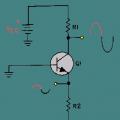 The simplest low-frequency amplifiers using transistors
 Calculation of cable cross-section by power