Lazy timer for the kitchen diagram. Clock for the kitchen: wall clock, timer clock for the kitchen, how to make it yourself, video instructions, clock in Provence style, photo examples. Provence style watch
This is another craft made from trash - a timer for the kitchen, although not necessarily for the kitchen. We used parts that were lying around idle, in particular old ALS indicators, resistors soldered from old boards, etc. The basis of the device is a microcontroller PIC16F628A, one of the most common and cheapest. The timer is controlled using a valcoder and one button. Time delay range from 1 to 99 minutes. At the end of the timing cycle, an intermittent sound signal is given. There are two firmwares in the archive, the first is just a timer, and the second with some bells and whistles, more on that below.

There is also an option for indicators with a common anode. Please note that the firmware for each of the schemes is different. All differences are highlighted in red on the diagram.

After turning on the power, the set time is displayed on the indicators, the LED does not light up. By rotating the encoder you can change the time setting from 1 to 99 minutes. When the time is set, press the button - a short beep sounds and the timer starts counting down, the LED flashes, and the time on the indicator decreases every minute. When the time has reached zero, the timer emits intermittent sound signals and the LED lights up continuously. Now, by pressing the button, the sound signal is removed and the device returns to its original state - time setting mode. This is how the first version of the firmware works.
The second version of the firmware works the same as the first, but has several additions. In the time setting mode, if you do not touch the encoder for several seconds, an animated screensaver starts running on the display. Pressing the button or rotating the encoder will turn off the animation and return to the time setting mode. During the countdown, if one minute remains, the display shows seconds from 60 to 00. When the sound signal is triggered, it will not sound indefinitely, but for about 20 seconds. Next, the display begins to display an animated screensaver (different from the one in installation mode). And also, after every minute it will remind you with a short sound signal. By pressing the button, just like in the first firmware, the timer is reset to time setting mode. When there are 3 seconds left before the timer goes off, the timer emits a short beep for every second, i.e. 3...2...1 and further works as usual. Both firmware are available and are in the archive along with a drawing of the printed circuit board.
The sound signal is implemented using hardware PWM built into the microcontroller. The dynamic head should have a resistance of about 50 ohms. You can also use low-impedance dynamic heads (4 or 8 ohms), but in this case it is better to install a small-sized output transformer, because A large current will flow through the 4 ohm head, which can overload the power supply and trigger a reset of the microcontroller.
Printed circuit board, version by Alexey Antonov

Comments
1 2
0 #21 kaktuss 06/14/2015 16:08
I quote AntonChip:
You can see a screenshot of setting configuration bits during programming
I asked the author what configuration was needed for the firmware, he replied that everything was already in the firmware. Therefore, I didn’t install anything, I just uploaded the firmware.
I would post screenshots, but I don't know how. Can I email it to you?
KITCHEN TIMER
People who cook know how easy it is to ruin a dish by being distracted by other things and forgetting to turn off the stove on time. Therefore, in front of meThe task was set to make a simple and easy-to-use timer for the kitchen. Of course, this function is built into almost any mobile phone, but not everyone knows how to use it, and it’s not convenient to search and configure it in the mobile phone menu every time. Ideally, you need a small-sized device that is controlled by simply pressing one button and does not contain scarce elements. Also, in everyday life, 3-4 time intervals are usually sufficient, which are used most often. The search for a suitable scheme in various radio magazines did not bring results - the proposed timers were either quite difficult to control, which could lead to an error when setting the countdown time by an untrained user, or were powered from the network, excluding their mobility, or were more expensive than purchasing a ready-made device. In this regard, I developed a scheme devoid of all these shortcomings.
The operation of the device is based on the gradual charging of a capacitor connected to the input of the operational amplifier to a voltage at whichswitching the state of the op-amp output, which in turn controls the sound generator. One of the advantages of the device is that it does not have a power switch - you just need to press one of the three switches to turn it on and start the desired countdown interval. At the same time, the LED lights up, indicating that the timer is turned on and the time delay is running. After a specified interval, a constant tone is heard.sound signal.By pressing the same switch again, we turn off the device.
The basis of the device is a quad operational amplifierL.M.324, and its three elementsare separate timers, and the fourth element is a sound generator. By pressing one of the switches corresponding to the desired time delay, let's sayS.A.1 - 5 minutes, power begins to flow to the circuit, and capacitor C1, connected in parallel with the switch contacts, ceases to be closed and begins to slowly charge through a resistorR1. Thus, at the moment of switching on, the potential at the inverting input of the op-amp is lower than at the non-inverting one, therefore the output of the op-amp has the potential of the supply voltage. Inverting input of the sound generator on the elementDA1.4 via diodeVD1 is under high potential, which blocks its operation - the speaker is silent. After the time required to charge capacitor C1 through the resistorR1, the potential at the inverting input of the op-amp will exceed the potential value at the non-inverting one. In this case, a low potential will be formed at the output of the op-amp - a diodeVD1 will be closed and the sound generator will start working. From pin 14, elementDA1.4, signal generated by the generator, through a resistorR4 and diodeVD1 goes to the base transistorVT1, to which the sound emitter is connected - a sound signal is heard. To turn off the device, you must press the switch againS.A.1, which disconnects the circuit from the power supply and simultaneously discharges capacitor C1 - the timer is ready for operation again.
The countdown time of the timer is determined by the values of elements C1 – C3 andR1 – R3. With the specified values of these parts, we will have the following time intervals;SA1 - 5 minutes,SA2 -10 minutes,SA3 - 20 minutes. If desired, you can change the dwell time of each timer by increasing or decreasing the values of the corresponding resistors and capacitors.
Setting up the device comes down to selecting capacitor C4, which determines the tone, and a resistorR5 - sound volume.
The printed circuit board was not developed, since surface mounting was used. Resistors MLT - 0.125, Timing capacitors C1 - C3 with the lowest possible leakage current, the rest K73 - 17. DiodesVD1- VD4 – KD521A, transistorVT1 will be replaced with KT817A,B. Red LEDH.L.1, You can use a flashing one, type UL-506S11FD-FB, which will allow you to get a time countdown effect. SwitchesSA1 –SA3 - any small-sized. A small speaker with a winding resistance of 8 ohms is suitable as a sound emitter; you can use a small sound emitter from Chinese soft toys, measuring 12x10 mm. You just need to achieve a high enough sound volume, otherwise the timer may not be heard in the background of operating household appliances. Power is supplied from a 6V battery. Changing the supply voltage within 4.5-12 volts has almost no effect on the timer exposure time, and only reduces the sound volume.
People who cook know how easy it is to ruin a dish by being distracted by other things and forgetting to turn off the stove on time. Therefore, at the request of my wife, I was given the task of making a simple and easy-to-use timer for the kitchen. Of course, this function is built into almost any mobile phone, but not everyone knows how to use it, and it’s inconvenient to search and configure it in the mobile phone menu every time. Ideally, you need a small-sized device that is controlled by simply pressing one button and does not contain scarce elements. In everyday life, 3-4 time intervals are usually sufficient, which are used most often. The search for a suitable scheme in various radio magazines did not bring results - the proposed timers were either quite difficult to control, which could lead to an error when setting the countdown time by an untrained user, or were powered from the network, excluding their mobility, or were more expensive than purchasing a ready-made device. In this regard, I developed a scheme that is devoid of all these shortcomings.
The operation of the device is based on the gradual charging of a capacitor connected to the input of the operational amplifier to a voltage at which the state of the op-amp output switches, which in turn controls the sound generator. One of the advantages of the device is that it does not have a power switch - you just need to press one of the three switches to turn it on and start the desired counting interval. At the same time, the LED lights up, indicating that the timer is turned on and the time delay is running. After a specified interval, a constant beep sounds. By pressing the same switch again, we turn off the device.
The basis of the device is a quad operational amplifier LM324, with three of its elements being separate timers, and the fourth element being a sound generator. By pressing one of the switches corresponding to the desired time delay, say SA1 - 5 minutes, power begins to flow to the circuit, and capacitor C1, connected in parallel with the switch contacts, ceases to be closed and begins to slowly charge through resistor R1. Thus, at the moment of switching on, the potential at the inverting input of the op-amp is lower than at the non-inverting one, therefore, the output of the op-amp has the potential of the supply voltage. The inverting input of the sound generator on the DA1.4 element through the VD1 diode is at a high potential, which blocks its operation - the speaker is silent.
After the time required to charge capacitor C1 through resistor R1, the potential at the inverting input of the op-amp will exceed the potential at the non-inverting input. In this case, a low potential will be formed at the output of the op-amp - diode VD1 will be closed and the sound generator will start working. From pin 14 of element DA1.4, the signal generated by the generator, through resistor R4 and diode VD1, is supplied to the base of transistor VT1, to which the sound emitter is connected, and a sound signal is heard. To turn off the device, you must press switch SA1 again, which disconnects the circuit from the power supply and at the same time discharges capacitor C1 - the timer is ready for operation again.
The countdown time of the timer is determined by the values of elements C1-SZ and R1-R3. With the specified values of these parts, we will have the following time intervals: SA1 - 5 minutes, SA2 - 10 minutes, SA3 - 20 minutes. If you wish, you can
change the dwell time of each timer by increasing or decreasing the values of the corresponding resistors and capacitors.
Setting up the device comes down to selecting capacitor C4, which determines the tone, and resistor R5, which determines the sound volume.
The printed circuit board was not developed, since surface mounting was used. Resistors MLT -0.125. Timing capacitors C1 - SZ with the lowest possible leakage current, the rest K73-17. Diodes VD1-VD4 - KD521A, replacement of transistor VT1 - KT817A, B. Red LED HL1, flashing can be used
UL-506S11FD-FB, which will allow you to get a countdown effect. Switches SA1-SA3 - any small-sized ones. A small speaker with a winding resistance of 8 ohms is suitable as a sound emitter; you can use a small sound emitter from Chinese soft toys, measuring 12x10 mm. You just need to achieve a high enough sound volume, otherwise the timer may not be heard in the background of operating household appliances. Power is supplied from a 6 V battery. Changing the supply voltage within 4.5 ... 12 V has almost no effect on the timer delay time, and only reduces the sound volume.
D.Yu. Kibardin, Khmelnitsky RA2"2010
| This diagram is also often viewed: |
For consideration and possible repetition, a very simple circuit, a very good timer. With convenient navigation through the menu, with a liquid crystal LCD display, with a real-time clock, with the minimum possible number of details, and with all this, you can program as many as one hundred time periods during the day.
Compact dimensions
Timer test video
The heart of this timer is the very popular and no longer expensive Atmega8 microcontroller. You can say that to flash the firmware we will need a programmer that we don’t have, but this is not true; to flash the Atmega firmware, just five short 10-15 cm wires connected through 150-200 Ohm resistors are enough. directly to the LPT port using this scheme.

It is for this reason that these microcontrollers have become the most popular among radio amateurs.
In this picture you see: Pinout diagram of MK legs for connection and firmware.

Step 1. Prepare everything you need to make a timer.
The most necessary radio components of the circuit, the rest can usually be picked up at home, the smallest microcircuit is the DS1307 clock.

We will need the following radioelements:
Integral clock DS1307
LCD liquid crystal indicator
Stabilizer 7805
500-1000 Mf - 16 volts.
Relay or electronic key (depending on the load that is planned to be connected).
resistance 5.1 kohm - 3 pcs., variable resistor (according to the LCD display manual).
Quartz clock 32768 Hz.
Momentary buttons - 4 pcs.
The battery is a 3 volt tablet.
Textolite for the board.
Small transformer ~220V. -> ~6-12c.
Junction box for the case.
+ For the programmer: resistors 150-200 Ohm. - 4 pcs., LPT port connector (for convenience, not required).
Mandatory tools for every radio amateur:
Soldering iron for soldering microcircuits, soldering iron for soldering passive radio components and wires.
Tester for testing tracks and checking radio components.
Tin, rosin.
+ Laser printer (for making a circuit board or another method).
Point 2. Let's start manufacturing.
We will make the timer according to this main scheme.

As you can see, there is no diagram of the power supply and output actuator on it, this is because you may decide to use an external stabilized power supply, and you also don’t know what load you plan to connect, therefore, everyone must choose the actuator themselves to suit their technical requirements.
Personally, I used this power supply circuit and an actuator on a transistor and a relay for my timer.

But you may want to use triacs, thyristors and triacs as an actuator; options for such circuits are shown below.


They are more compact (no heatsink), but less powerful than a simple relay.
In accordance with the main circuit diagram + PSU + IU and analysis of the mounting dimensions of your box for the case, as well as the dimensions of the selected radio elements, we design the shape, size and pattern of the tracks on the board. To do this, it is convenient to use the Sprint Layout program.
For my device I got this simple board.

We transfer the resulting drawing using a special marker or using LUT technology (using a laser printer and iron) onto a copper layer of PCB. If you have a Brother laser printer (like me), then it’s better to immediately abandon the idea of LUT, due to the refractory toner used in it ~400C instead of the usual ~200C; by the way, I once foolishly bought this printer specifically for LUT :(. , so as a result my board is drawn with a marker.
The pattern applied to the copper is etched in a bath of ferric chloride or any other special solution.

We solder the parts onto the finished board according to the diagram, paying special attention when installing and soldering the clock chip and quartz element. The length of the tracks between them should be minimal, but it is better to use micro quartz from a wristwatch and solder it directly to the MC legs of the watch. We fill all the free space next to the clock and quartz MC with housing pads (GND). The battery is needed to keep the watch running while unplugged. If for some reason you did not install this battery, then connect the positive wire to the case, otherwise the clock simply will not work.
We flash the microcontroller with a programmer or using 5 wires.
*Firmware* (downloads: 1396)
The author of the firmware was created specifically for convenience (for which we thank him) and did not change the factory fuses, which makes it very easy, without any problems, to install the firmware for a novice radio amateur. If the MK has not yet been used, it’s new from the store, then just upload the firmware and that’s it, but if there are already changes in the fuses, then you need to set them like CKSEL=0001. Everything else is simple and needs no explanation.
Point 3. Assembly.
It is very convenient to use plastic junction boxes for the case; they come in different sizes and shapes.


Using hot glue from a gun, we fix the LCD screen into the cover cut with a knife, cut holes for the control buttons and the power button.


Trim the protruding glue.
In the culinary art, maintaining the accuracy of time plays no less important role than the accuracy of following the recipe. This timer is designed specifically for use in the kitchen, it is very easy to use and allows you to set any time delay in the range from one minute to 99 minutes, in steps of a minute, by rotating the handles of two switches. The end of the set time interval is indicated by a tonal, fairly loud sound signal that sounds for one minute (if not turned off earlier).
The timer is not intended to control electrical appliances; its task is to inform the cook that the cooking time has expired.
The circuit diagram is shown in the figure above. There are only three counter chips of the K176 series. D1 is a clock chip, in this case it produces minute pulses and a pulse signal with a frequency of 1024 Hz, which serves for sound indication. D1 contains two counters, the first lower one produces, along with other signals, pulses with a frequency of 1 Hz, and the second upper one contains a divider of these pulses by 60, so at pin 10 of D1 pulses with a repetition rate of one minute are obtained.
Pulses with a frequency of 1 Hz are also supplied to the transistor switch VT1, in the collector circuit of which an LED is turned on, blinking during the operation of the timer with a period of one second.
Minute pulses with pin. 10 D1 are fed to a two-digit decimal counter on two identical chips D2 and D3. The time is set using switches S1 and S2, with S1 setting the units of minutes, and S2 - tens. For example, if you need a time of 63 minutes, set S1 to position “3”, and S2 to position “6”.
The sound-emitting device consists of transistor VT2, miniature speaker B1 and logic element “3rd” on resistor R6 and diodes VD2-VD4. While the installed counter outputs have logical zeros (or one of them has a zero), at least one of the diodes VD2 and VD4 receives a logical zero through switch S1 or S2. In this case, the diode is open and zero is also set at the connection point between R6 and R7. As soon as the set time expires, both diodes receive ones and they close. As a result, a high level voltage is supplied to the VT2 base through R6-R7.
And in order to receive a tone signal, this voltage is interrupted at a frequency of 1024 Hz using a diode VD3, the cathode of which receives this frequency from pin 11 D1. The timer is set to zero at the moment the power is turned on using capacitor C5, the charging current of which sets all four counters to zero states.
Structurally, the timer is made in a small plastic box for various small items; the handles of two biscuit switches are located on the lid and circular scales of tens and units of minutes are drawn. The speaker is also attached to this cover. Switch SB1 toggle switch. The timer is powered by two 4.5 V flat batteries connected in series.
It is possible to install a standard connector and power the timer from a 9 V network adapter for portable audio equipment. During the setup process, you may have to select the ratio of resistors R7 and R8 in such a way that the speaker does not sound until the set time has elapsed.
Any electrodynamic or electromagnetic low-power sound emitter is suitable as a speaker, for example, an electromagnetic capsule from a telephone, a speaker from a radio, etc. Chips K176IE8 can be replaced with K561IE8. Transistors KT315 - any corresponding power and structure. KD521 diodes are any low-power pulse or rectifier, and even better if they are germanium type D9. The LED is also of any visible spectrum.
Kitchen timer circuit board view
 DIY brick foundation: strip and columnar
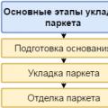 How to lay parquet: methods, necessary tools and step-by-step process for proper installation
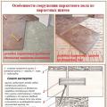 How to lay parquet: methods, necessary tools and step-by-step process for proper installation