DIY 5V power supply. A good laboratory power supply with your own hands. PCB manufacturing
The 12 volt DC power supply consists of three main parts:
- A step-down transformer from a conventional input alternating voltage of 220 V. At its output there will be the same sinusoidal voltage, only reduced to approximately 16 volts at idle - without load.
- Rectifier in the form of a diode bridge. It “cuts off” the lower half-sine waves and puts them up, that is, the resulting voltage varies from 0 to the same 16 volts, but in the positive region.
- A high-capacity electrolytic capacitor that smooths out the half-sine voltage, making it approach a straight line at 16 volts. This smoothing is better, the larger the capacitor capacity.
The simplest thing you need to obtain a constant voltage capable of powering devices designed for 12 volts - light bulbs, LED strips and other low-voltage equipment.
A step-down transformer can be taken from an old computer power supply or simply bought in a store so as not to bother with windings and rewinding. However, in order to ultimately reach the desired 12 volts of voltage with a working load, you need to take a transformer that lowers the volts to 16.
For the bridge, you can take four 1N4001 rectifier diodes, designed for the voltage range we need or similar.
The capacitor must have a capacity of at least 480 µF. For good output voltage quality, you can use more, 1,000 µF or higher, but this is not at all necessary to power lighting devices. The operating voltage range of the capacitor is needed, say, up to 25 volts.
Device layout
If we want to make a decent device that we won’t be ashamed to attach later as a permanent power supply, say, for a chain of LEDs, we need to start with a transformer, a board for mounting electronic components and a box where all this will be fixed and connected. When choosing a box, it is important to consider that the electrical circuits heat up during operation. Therefore, it is good to find a box that is suitable in size and with holes for ventilation. You can buy it in a store or take a case from a computer power supply. The latter option may be cumbersome, but as a simplification you can leave the existing transformer in it, even along with the cooling fan.

On the transformer we are interested in the low-voltage winding. If it reduces the voltage from 220 V to 16 V, this is an ideal case. If not, you'll have to rewind it. After rewinding and checking the voltage at the output of the transformer, it can be mounted on the circuit board. And immediately think about how the circuit board will be attached inside the box. It has mounting holes for this.


Further installation steps will take place on this mounting board, which means that it must be sufficient in area, length and allow the possible installation of radiators on diodes, transistors or a microcircuit, which must still fit into the selected box.
We assemble the diode bridge on the circuit board, you should get such a diamond of four diodes. Moreover, the left and right pairs consist equally of diodes connected in series, and both pairs are parallel to each other. One end of each diode is marked with a stripe - this is indicated by a plus. First we solder the diodes in pairs to each other. In series - this means the plus of the first is connected to the minus of the second. The free ends of the pair will also turn out - plus and minus. Connecting pairs in parallel means soldering both pluses of the pairs and both minuses. Now we have the output contacts of the bridge - plus and minus. Or they can be called poles - upper and lower.

The remaining two poles - left and right - are used as input contacts, they are supplied with alternating voltage from the secondary winding of the step-down transformer. And the diodes will supply a pulsating voltage of constant sign to the bridge outputs.
If you now connect a capacitor in parallel with the output of the bridge, observing the polarity - to the plus of the bridge - plus of the capacitor, it will begin to smooth out the voltage, and as well as its capacitance is large. 1,000 uF will be enough, and even 470 uF is used.
Attention! An electrolytic capacitor is an unsafe device. If it is connected incorrectly, if voltage is applied to it outside the operating range, or if it is overheated, it may explode. At the same time, all its internal contents scatter around the area - tatters of the case, metal foil and splashes of electrolyte. Which is very dangerous.
Well, here we have the simplest (if not primitive) power supply for devices with a voltage of 12 V DC, that is, direct current.
Problems with a simple power supply with a load
The resistance drawn on the diagram is the equivalent of the load. The load must be such that the current supplying it, with an applied voltage of 12 V, does not exceed 1 A. You can calculate the load power and resistance using the formulas.

Where does the resistance R = 12 Ohm, and the power P = 12 watts come from? This means that if the power is more than 12 watts and the resistance is less than 12 ohms, then our circuit will begin to work with overload, will get very hot and will quickly burn out. There are several ways to solve the problem:
- Stabilize the output voltage so that when the load resistance changes, the current does not exceed the maximum permissible value or when there are sudden current surges in the load network - for example, when some devices are turned on - the peak current values are cut to the nominal value. Such phenomena occur when the power supply powers radio-electronic devices - radios, etc.
- Use special protection circuits that would turn off the power supply if the load current exceeds.
- Use more powerful power supplies or power supplies with more power reserves.
The figure below shows the development of the previous simple circuit by including a 12-volt stabilizer LM7812 at the output of the microcircuit.

This is already better, but the maximum load current of such a stabilized power supply unit should still not exceed 1 A.
High Power Power Supply
The power supply can be made more powerful by adding several powerful stages using TIP2955 Darlington transistors to the circuit. One stage will provide an increase in load current of 5 A, six composite transistors connected in parallel will provide a load current of 30 A.

A circuit with this kind of power output requires adequate cooling. Transistors must be provided with heat sinks. You may also need an additional cooling fan. In addition, you can protect yourself with fuses (not shown in the diagram).
The figure shows the connection of one composite Darlington transistor, which makes it possible to increase the output current to 5 amperes. You can increase it further by connecting new cascades in parallel with the specified one.
Attention! One of the main disasters in electrical circuits is a sudden short circuit in the load. In this case, as a rule, a current of gigantic power arises, which burns everything in its path. In this case, it is difficult to come up with such a powerful power supply that can withstand this. Then protection circuits are used, ranging from fuses to complex circuits with automatic shutdown on integrated circuits.
When you assemble any electronic homemade product, you need a power supply to test it. There is a wide variety of ready-made solutions on the market. Beautifully designed, have many functions. There are also many kits for DIY production. I'm not even talking about the Chinese with their trading platforms. I bought step-down converter module boards on Aliexpress, so I decided to make them on it. The voltage is regulated, there is enough current. The unit is based on a module from China, as well as radio components that were in my workshop (they had been lying around for a long time and were waiting in the wings). The unit regulates from 1.5 volts to the maximum (it all depends on the rectifier used to the adjustment board.
Description of components
I have a 17.9 Volt transformer with a current of 1.7 Ampere. It is installed in the housing, which means there is no need to select the latter. The winding is quite thick, I think it will handle 2 Amps. Instead of a transformer, you can use a switching power supply for a laptop, but then you also need a housing for the remaining components.
The AC rectifier will be a diode bridge; it can also be assembled from four diodes. An electrolytic capacitor will smooth out the ripples; I have 2200 microfarads and an operating voltage of 35 volts. I used it used, it was in stock.

I will regulate the output voltage. There are a wide variety of them on the market. It provides good stabilization and is quite reliable.

To conveniently adjust the output voltage, I will use a 4.7 kOhm adjustment resistor. The board has 10 kOhm installed, but I’ll install whatever I had. The resistor is from the early 90s. With this rating, adjustment is ensured smoothly. I also picked up a handle for it, also from a shaggy age.

The output voltage indicator is . It has three wires. Two wires power the voltmeter (red and black), and the third (blue) is measuring. You can combine red and blue together. Then the voltmeter will be powered from the output voltage of the unit, that is, the indication will light up from 4 volts. Agree, it’s not convenient, so I’ll feed it separately, more on that later.

To power the voltmeter, I will use a domestic 12-volt voltage stabilizer chip. This will ensure that the voltmeter indicator operates at a minimum. The voltmeter is powered through the red plus and black minus. The measurement is carried out through the black minus and blue plus output of the block.

My terminals are domestic. They have holes for banana plugs and holes for clamping wires. Similar . I also selected wires with lugs.

Power supply assembly
Everything is assembled according to a simple sketched diagram.
The diode bridge must be soldered to the transformer. I bent it for comfortable installation. A capacitor was soldered to the output of the bridge. It turned out not to go beyond the height dimensions.

I screwed the power supply arm of the voltmeter to the transformer. In principle, it does not heat up, and so it stands in its place and does not bother anyone.

I removed a resistor on the regulator board and soldered two wires under the remote resistor. I also soldered wires under the output terminals.

Mark holes on the case for everything that will be on the front panel. I cut holes for a voltmeter and one terminal. I install the resistor and the second terminal at the junction of the box. When assembling the box, everything will be fixed by compressing both halves.

The terminal and voltmeter are installed.

This is how it turned out to install the second terminal and the adjusting resistor. I made a cutout for the resistor key.

Cut out a window for the switch. We assemble the housing and close it. All that remains is to wire the switch and the regulated power supply is ready for use.
This is how the regulated power supply turned out. This design is simple and can be repeated by anyone. The parts are not rare.
Good luck with making everyone!
A power supply is an essential requirement of any technology. Thanks to this device, it is possible to regulate the voltage level, thereby preventing premature breakdown of the electrical structure.
Today, assembling an adjustable power supply with your own hands is quite simple. There are many diagrams on the Internet that help make the task easier even for beginner radio amateurs. The process of making this design is quite exciting and interesting.

Before you begin the work process, you need to select a simple circuit for making a power supply. The lighter the drawing, the faster it will be possible to assemble the installation. Specialty stores offer a wide range of radio and electrical parts for this design.


Types and types of power supplies
Before you begin assembling the device, you need to familiarize yourself with the types and types of power supplies. Each model has its own characteristic features.

These include:
- stabilized types. They are responsible for the smooth operation of the electrical device;
- uninterrupted views. They allow the device to operate even when disconnected from the electrical circuit.

Classification by operating principle
Based on their operating principle, they are classified into the following types. These include:

Pulse. It is an inverter system in which alternating current is converted into direct high-frequency voltage.

In order to make a switching power supply with your own hands, you need to purchase a special galvanic isolation that will transfer the converted power to the transformer installation.

Transformer. It consists of a step-down transformer and a special rectifier. It further converts alternating power into direct power. A filter capacitor is additionally installed here. It allows you to smooth out excessive pulsation and vibrations during operation of the device.


Master class on making an adjustable power supply
How to make such a device at home? Detailed instructions on how to make a power supply with your own hands will help you cope with the task. The first step is to have a clear idea for what purposes this device will be assembled.

The main principles of operation of the structure is the supply of maximum current, which will subsequently be directed towards the load. In addition, it will provide output voltage. Thanks to this, the electrical device can function normally.

Making a powerful power supply with your own hands is quite simple. A special output voltage limiter is installed here, which allows you to regulate the current supply process using a handle.

For example, a device outputs from 3 to 15 W, and the device requires 5 W. To do this, we change the range of converted power by using a certain position of the regulator.

What can a power supply be made from?
You will need the following parts:
- transformer;
- diode bridge;
- chip;
- capacitor filter;
- throttle;
- protection blocks;
- Voltage regulator.

The transformer can have a power within 10 W. As a rule, its winding can withstand voltage from 220 W to 250 W. The secondary winding conducts from 20 to 50 W.


This part can be bought in a specialized department or found in any old electrical appliance.

The microcircuit is produced under a certain marking (PDIP – 8). Here you can make an unlimited number of conductive electrical tracks.


The diode bridge is made of four diodes measuring 0.2 x 0.5 mm. SOIC series products significantly reduce electrical voltage fluctuations.

The protection units will be made of two fuses of the FU2 brand. When these products are triggered, a current of 0.16A is generated. Chokes L1 and L2 can be made independently. To do this, you will need two elements made of magnetic ferrite. Their size should be K 17.5 x 8.3 x 6 mm.

All elements are connected according to a specific diagram, which is presented below. Here, each part is marked with a corresponding designation. The photo of a homemade power supply shows the finished device.


DIY photo of power supplies


![]()


So the next device has been assembled, now the question arises: what to power it from? Batteries? Batteries? No! The power supply is what we will talk about.
Its circuit is very simple and reliable, it has short-circuit protection and smooth adjustment of the output voltage.
A rectifier is assembled on the diode bridge and capacitor C2, circuit C1 VD1 R3 is a reference voltage stabilizer, circuit R4 VT1 VT2 is a current amplifier for power transistor VT3, protection is assembled on transistor VT4 and R2, and resistor R1 is used for adjustment.
I took the transformer from an old charger from a screwdriver, at the output I got 16V 2A
As for the diode bridge (at least 3 amperes), I took it from an old ATX block as well as electrolytes, a zener diode, and resistors.
I used a 13V zener diode, but the Soviet D814D is also suitable.
The transistors were taken from an old Soviet TV; transistors VT2, VT3 can be replaced with one component, for example KT827.
Resistor R2 is a wirewound with a power of 7 Watts and R1 (variable) I took nichrome for adjustment without jumps, but in its absence you can use a regular one.
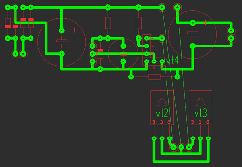
It consists of two parts: the first one contains the stabilizer and protection, and the second one contains the power part.
All parts are mounted on the main board (except for power transistors), transistors VT2, VT3 are soldered onto the second board, we attach them to the radiator using thermal paste, there is no need to insulate the housing (collectors). The circuit was repeated many times and does not need adjustment. Photos of two blocks are shown below with a large 2A radiator and a small 0.6A.

Indication
Voltmeter: for it we need a 10k resistor and a 4.7k variable resistor and I took an indicator m68501, but you can use another one. From resistors we will assemble a divider, a 10k resistor will prevent the head from burning out, and with a 4.7k resistor we will set the maximum deviation of the needle.
After the divider is assembled and the indication is working, you need to calibrate it; to do this, open the indicator and glue clean paper onto the old scale and cut it along the contour; it is most convenient to cut the paper with a blade.

When everything is glued and dry, we connect the multimeter in parallel to our indicator, and all this to the power supply, mark 0 and increase the voltage to volts, mark, etc.
Ammeter: for it we take a resistor of 0.27 ohm!!! and variable at 50k, The connection diagram is below, using a 50k resistor we will set the maximum deviation of the arrow.
The graduation is the same, only the connection changes, see below; a 12 V halogen light bulb is ideal as a load.
List of radioelements
| Designation | Type | Denomination | Quantity | Note | Shop | My notepad |
|---|---|---|---|---|---|---|
| VT1 | Bipolar transistor | KT315B | 1 | To notepad | ||
| VT2, VT4 | Bipolar transistor | KT815B | 2 | To notepad | ||
| VT3 | Bipolar transistor | KT805BM | 1 | To notepad | ||
| VD1 | Zener diode | D814D | 1 | To notepad | ||
| VDS1 | Diode bridge | 1 | To notepad | |||
| C1 | 100uF 25V | 1 | To notepad | |||
| C2, C4 | Electrolytic capacitor | 2200uF 25V | 2 | To notepad | ||
| R2 | Resistor | 0.45 Ohm | 1 | To notepad | ||
| R3 | Resistor | 1 kOhm | 1 | To notepad | ||
| R4 | Resistor |
DC power supplies are needed not only by radio amateurs. They have a very wide scope of application, and therefore most home craftsmen use them to one degree or another. This article describes the main types of voltage converters, their characteristic differences and applications, and how to make a simple power supply with your own hands.
Doing it yourself will save you a lot of money. Once you understand the device and operating principle, you can easily repair this device.

Areas of use
These devices have a very wide range of applications. Let's look at the main uses. To save battery life, low-voltage power tools are connected to homemade power supplies. Such devices are used for connecting LED lighting devices, installing lighting in rooms with high humidity and danger of electric shock, and for many other purposes not directly related to radio electronics.


Device classification
Most power supplies convert AC mains voltage of 220 volts into DC voltage of a given value. Moreover, the device is characterized by a large list of operating parameters that must be taken into account when purchasing or designing.

The main operating parameters are output current, voltage and the ability to stabilize and adjust the output voltage. All these converters are classified into two large groups according to the conversion method: analog and pulse devices. These groups of power supplies have strong differences and are easily distinguished from the photo at first glance.

Previously, only analog devices were produced. In them, voltage conversion is carried out using a transformer. Collecting such a source is not difficult. Its scheme is quite simple. It consists of a step-down transformer, a diode bridge and a stabilizing capacitor.

Diodes convert AC voltage to DC voltage. The capacitor further smoothes it out. The disadvantage of such devices is their large dimensions and weight.

A 250-watt transformer weighs several kilograms. In addition, the voltage at the output of such devices can change due to external factors. Therefore, to stabilize the output parameters in such devices, special elements are added to the electronic circuit.

High-power power supplies are manufactured using transformers. It is advisable to use such devices for charging car batteries or for connecting electric drills to save the life of lithium batteries.

The advantage of such a device is the galvanic isolation between the two windings (with the exception of autotransformers). The primary winding connected to the high voltage network has no physical contact with the secondary winding. A reduced voltage is generated on it.

Energy transfer is carried out using an alternating current magnetic field in the metal core of the transformer. If you have minimal knowledge in radio electronics, it is easier to assemble a classic adjustable power supply using a transformer with your own hands.


With the development of electronic technology, it has become possible to produce cheaper semiconductor voltage converters. They are very compact, light in weight and have a very low price. Thanks to this, they became market leaders. Every apartment uses several different power supplies.

Unfortunately, most modern devices do not have galvanic isolation from the power supply. Because of this, quite often people die who use the device while charging a cell phone or other equipment and at the same time take a bath or wash their face.

If safety precautions are followed, there is no danger to a person. These devices are quite low in cost and when they break down, they often do not try to repair them, but purchase a new device. However, if you understand the circuits and operating principles of switching power supplies, you can easily both repair such a power supply and assemble a new device.

Switching power supplies
Let's look at the design and operating principle of switching power supplies. In such devices, the alternating mains voltage is converted into high-frequency voltage at the input. To transform high-frequency currents, it is not large transformers that are required, but miniature electromagnetic coils. Therefore, such converters easily fit into small housings. For example, they can easily be placed in the plastic socket of an energy-saving lamp.


The layout of such a power supply in a small device does not cause any problems. For reliable operation, it is necessary to provide the possibility of cooling the heating elements of the electronic circuit on special metal radiators. The converted voltage is rectified using high-speed diodes and smoothed at the output filter.

The disadvantage of such devices is the inevitable presence of high-frequency interference at the output of the converter, despite the presence of special filters. In addition, pulsed devices use special output voltage stabilization circuits.


The switching power supply can be purchased as a separate unit, ready for installation in the device. You can also assemble this device yourself using widely available diagrams and instructions for assembling power supplies.

It should be taken into account that self-assembly may be more expensive than a purchased product purchased online in the Asian market. This may be due to the fact that electronic components are sold at a higher markup than the manufacturer's markup in China for the assembly of the product and its delivery. In any case, having understood the structure of such devices, it will be possible not only to assemble such a device yourself, but also, if necessary, to repair it. Such skills will be very useful.

If you want to save money, you can use switching power supplies from personal computers. Often, a faulty personal computer contains a working unit. They require minimal modification before use.

Such power supplies have idle protection. They must be under load at all times. Therefore, in order to avoid shutdown, a constant resistance is included in the load. Such modernized units are used primarily to power household power tools.

DIY photo of power supplies


 How to choose the right cable cross-section
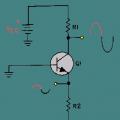 The simplest low-frequency amplifiers using transistors
 Calculation of cable cross-section by power