Why does a capacitor not pass direct current, but allow alternating current to pass? Capacitors What current flows through a capacitor
It was talked about electrolytic capacitors. They are mainly used in DC circuits, as filter tanks in rectifiers. Also, you cannot do without them in decoupling power supply circuits of transistor cascades, stabilizers and transistor filters. At the same time, as was said in the article, they do not pass direct current, and they do not want to work with alternating current at all.
There are non-polar capacitors for alternating current circuits, and their many types indicate that the operating conditions are very diverse. In cases where high stability of parameters is required and the frequency is sufficiently high, air and ceramic capacitors are used.
The parameters of such capacitors are subject to increased requirements. First of all, this is high accuracy (small tolerance), as well as an insignificant temperature coefficient of the TKE capacitance. As a rule, such capacitors are placed in the oscillatory circuits of receiving and transmitting radio equipment.
If the frequency is low, for example, the frequency of the lighting network or the frequency of the audio range, then it is quite possible to use paper and metal-paper capacitors.
Capacitors with a paper dielectric have linings made of thin metal foil, most often aluminum. The thickness of the plates ranges from 5...10 µm, which depends on the design of the capacitor. Between the plates there is a dielectric made of capacitor paper impregnated with an insulating composition.
In order to increase the operating voltage of the capacitor, the paper can be laid in several layers. This entire package is rolled up like a carpet and placed in a round or rectangular body. In this case, of course, conclusions are drawn from the plates, but the body of such a capacitor is not connected to anything.
Paper capacitors are used in low-frequency circuits at high operating voltages and significant currents. One such very common application is connecting a three-phase motor to a single-phase network.
In metal-paper capacitors, the role of plates is played by a thin layer of metal, the same aluminum, sprayed in a vacuum onto the capacitor paper. The design of capacitors is the same as paper capacitors, although the dimensions are much smaller. The scope of application of both types is approximately the same: direct, pulsating and alternating current circuits.
The design of paper and metal-paper capacitors, in addition to capacitance, also provides these capacitors with significant inductance. This leads to the fact that at some frequency the paper capacitor turns into a resonant oscillatory circuit. Therefore, such capacitors are used only at frequencies of no more than 1 MHz. Figure 1 shows paper and metal-paper capacitors produced in the USSR.
Picture 1.
Antique metal-paper capacitors had the property of self-healing after breakdown. These were capacitors of the MBG and MBGCh types, but now they have been replaced by capacitors with a ceramic or organic dielectric of types K10 or K73.
In some cases, for example, in analog storage devices, or otherwise, sample-and-hold devices (SSDs), special requirements are imposed on capacitors, in particular, low leakage current. Then capacitors come to the rescue, the dielectrics of which are made of materials with high resistance. First of all, these are fluoroplastic, polystyrene and polypropylene capacitors. Mica, ceramic and polycarbonate capacitors have slightly lower insulation resistance.
These same capacitors are used in pulse circuits when high stability is required. Primarily for the formation of various time delays, pulses of a certain duration, as well as for setting the operating frequencies of various generators.
To make the timing parameters of the circuit even more stable, in some cases it is recommended to use capacitors with a higher operating voltage: there is nothing wrong with installing a capacitor with an operating voltage of 400 or even 630V in a circuit with a voltage of 12V. Such a capacitor will, of course, take up more space, but the stability of the entire circuit as a whole will also increase.

The electrical capacitance of capacitors is measured in Farads F (F), but this value is very large. Suffice it to say that the capacity of the Earth does not exceed 1F. In any case, this is exactly what is written in physics textbooks. 1 Farad is the capacitance at which, with a charge q of 1 coulomb, the potential difference (voltage) across the capacitor plates is 1V.
From what has just been said, it follows that the Farad is a very large value, so in practice smaller units are more often used: microfarads (μF, μF), nanofarads (nF, nF) and picofarads (pF, pF). These values are obtained by using submultiple and multiple prefixes, which are shown in the table in Figure 2.

Figure 2.
Modern parts are becoming smaller and smaller, so it is not always possible to apply full markings on them; various symbol systems are increasingly being used. All these systems in the form of tables and explanations for them can be found on the Internet. Capacitors intended for SMD mounting most often do not have any markings at all. Their parameters can be read on the packaging.
In order to find out how capacitors behave in alternating current circuits, it is proposed to perform several simple experiments. At the same time, there are no special requirements for capacitors. The most common paper or metal-paper capacitors are quite suitable.
Capacitors conduct alternating current
To see this with your own eyes, it is enough to assemble a simple circuit shown in Figure 3.
Figure 3.
First you need to turn on the lamp through capacitors C1 and C2 connected in parallel. The lamp will glow, but not very brightly. If we now add another capacitor C3, the glow of the lamp will noticeably increase, which indicates that the capacitors resist the passage of alternating current. Moreover, a parallel connection, i.e. Increasing the capacitance reduces this resistance.
Hence the conclusion: the larger the capacitance, the lower the resistance of the capacitor to the passage of alternating current. This resistance is called capacitive and is denoted in formulas as Xc. Xc also depends on the frequency of the current; the higher it is, the less Xc. This will be discussed a little later.
Another experiment can be done using an electricity meter, having first disconnected all consumers. To do this, you need to connect three 1 µF capacitors in parallel and simply plug them into a power outlet. Of course, you need to be extremely careful, or even solder a standard plug to the capacitors. The operating voltage of the capacitors must be at least 400V.
After this connection, it is enough to simply observe the meter to make sure that it is in place, although according to calculations, such a capacitor is equivalent in resistance to an incandescent lamp with a power of about 50 W. The question is, why doesn’t the counter turn? This will also be discussed in the next article.
This can be easily confirmed by experiments. You can light a light bulb by connecting it to an AC power supply through a capacitor. The loudspeaker or handsets will continue to work if they are connected to the receiver not directly, but through a capacitor.
A capacitor consists of two or more metal plates separated by a dielectric. This dielectric is most often mica, air or ceramics, which are the best insulators. It is quite natural that direct current cannot pass through such an insulator. But why does alternating current pass through it? This seems all the more strange since the same ceramics in the form of, for example, porcelain rollers perfectly insulate alternating current wires, and mica perfectly functions as an insulator in electric irons and other heating devices that operate properly on alternating current.
Through some experiments we could “prove” an even stranger fact: if in a capacitor a dielectric with comparatively poor insulating properties is replaced by another dielectric that is a better insulator, then the properties of the capacitor will change so that the passage of alternating current through the capacitor will not be hindered, but rather on the contrary, it is facilitated. For example, if you connect a light bulb to an alternating current circuit through a capacitor with a paper dielectric and then replace the paper with such an excellent insulator; like glass or porcelain of the same thickness, the light bulb will begin to burn brighter. Such an experiment will lead to the conclusion that alternating current not only passes through the capacitor, but that it also passes the more easily the better the insulator its dielectric is.
However, despite all the apparent convincingness of such experiments, electric current - neither direct nor alternating - does not pass through the capacitor. The dielectric separating the plates of the capacitor serves as a reliable barrier to the path of current, whatever it may be - alternating or direct. But this does not mean that there will be no current in the entire circuit in which the capacitor is connected.

A capacitor has a certain physical property that we call capacitance. This property consists of the ability to accumulate electrical charges on the plates. A source of electric current can be roughly likened to a pump that pumps electrical charges into a circuit. If the current is constant, then electrical charges are pumped all the time in one direction.
How will a capacitor behave in a DC circuit?
Our “electric pump” will pump charges onto one of its plates and pump them out from the other plate. The ability of a capacitor to hold a certain difference in the number of charges on its plates is called its capacity. The larger the capacitance of the capacitor, the more electrical charges can be on one plate compared to the other.
At the moment the current is turned on, the capacitor is not charged - the number of charges on its plates is the same. But the current is on. The “electric pump” started working. He drove the charges onto one plate and began pumping them out from the other. Once the movement of charges begins in the circuit, it means that current begins to flow in it. Current will flow until the capacitor is fully charged. Once this limit is reached, the current will stop.
Therefore, if there is a capacitor in a DC circuit, then after it is closed, the current will flow in it for as long as it takes to fully charge the capacitor.
If the resistance of the circuit through which the capacitor is charged is relatively small, then the charging time is very short: it lasts an insignificant fraction of a second, after which the current flow stops.
The situation is different in the alternating current circuit. In this circuit, the “pump” pumps electrical charges in one direction or the other. Having barely created an excess of charges on one plate of the capacitor compared to the number on the other plate, the pump begins to pump them in the opposite direction. Charges will circulate continuously in the circuit, which means that, despite the presence of a non-conducting capacitor, there will be a current in it - the charge and discharge current of the capacitor.
What will the magnitude of this current depend on?
By current magnitude we mean the number of electrical charges flowing per unit time through the cross section of a conductor. The greater the capacitance of the capacitor, the more charges will be required to “fill” it, which means the stronger the current in the circuit will be. The capacitance of a capacitor depends on the size of the plates, the distance between them and the type of dielectric separating them, its dielectric constant. Porcelain has a greater dielectric constant than paper, so when replacing paper with porcelain in a capacitor, the current in the circuit increases, although porcelain is a better insulator than paper.
The magnitude of the current also depends on its frequency. The higher the frequency, the greater the current will be. It is easy to understand why this happens by imagining that we fill a container with a capacity of, for example, 1 liter with water through a tube and then pump it out from there. If this process is repeated once per second, then 2 liters of water will flow through the tube per second: 1 liter in one direction and 1 liter in the other. But if we double the frequency of the process: we fill and empty the vessel 2 times per second, then 4 liters of water will flow through the tube per second - increasing the frequency of the process with the same capacity of the vessel led to a corresponding increase in the amount of water flowing through the tube.
From all that has been said, the following conclusions can be drawn: electric current - neither direct nor alternating - does not pass through the capacitor. But in the circuit connecting the AC source to the capacitor, the charge and discharge current of this capacitor flows. The larger the capacitance of the capacitor and the higher the frequency of the current, the stronger this current will be.
This feature of alternating current is extremely widely used in radio engineering. The emission of radio waves is also based on it. To do this, we excite a high-frequency alternating current in the transmitting antenna. But why does current flow in the antenna, since it is not a closed circuit? It flows because there is capacitance between the antenna and counterweight wires or ground. The current in the antenna represents the charge and discharge current of this capacitor, this capacitor.
In all radio engineering and electronic devices, in addition to transistors and microcircuits, capacitors are used. Some circuits have more of them, others have less, but there is practically no electronic circuit without capacitors.
At the same time, capacitors can perform a variety of tasks in devices. First of all, these are capacitances in the filters of rectifiers and stabilizers. Using capacitors, a signal is transmitted between amplifier stages, low- and high-pass filters are built, time intervals are set in time delays, and the oscillation frequency in various generators is selected.
Capacitors trace their origins back to , which was used by the Dutch scientist Pieter van Musschenbroeck in his experiments in the mid-18th century. He lived in the city of Leiden, so it’s not hard to guess why this jar was called that.
Actually, it was an ordinary glass jar, lined inside and outside with tin foil - staniol. It was used for the same purposes as modern aluminum, but aluminum had not yet been discovered.
The only source of electricity in those days was an electrophore machine, capable of developing voltages up to several hundred kilovolts. This is where the Leyden jar was charged. Physics textbooks describe a case when Muschenbroek discharged his can through a chain of ten guardsmen holding hands.
At that time, no one knew that the consequences could be tragic. The blow was quite sensitive, but not fatal. It didn’t come to this, because the capacity of the Leyden jar was insignificant, the pulse was very short-lived, so the discharge power was low.
How does a capacitor work?
The design of a capacitor is practically no different from a Leyden jar: the same two plates separated by a dielectric. This is exactly how capacitors are depicted on modern electrical diagrams. Figure 1 shows a schematic design of a flat-plate capacitor and the formula for its calculation.

Figure 1. Design of a parallel-plate capacitor
Here S is the area of the plates in square meters, d is the distance between the plates in meters, C is the capacitance in farads, ε is the dielectric constant of the medium. All quantities included in the formula are indicated in the SI system. This formula is valid for the simplest flat capacitor: you can simply place two metal plates next to each other, from which conclusions are drawn. Air can serve as a dielectric.
From this formula it can be understood that the larger the area of the plates and the smaller the distance between them, the greater the capacitance of the capacitor. For capacitors with a different geometry, the formula may be different, for example, for the capacitance of a single conductor or. But the dependence of the capacitance on the area of the plates and the distance between them is the same as that of a flat capacitor: the larger the area and the smaller the distance, the greater the capacitance.
In fact, the plates are not always made flat. For many capacitors, for example metal-paper capacitors, the plates are aluminum foil rolled together with a paper dielectric into a tight ball, shaped like a metal case.
To increase the electrical strength, thin capacitor paper is impregnated with insulating compounds, most often transformer oil. This design makes it possible to make capacitors with a capacity of up to several hundred microfarads. Capacitors work in much the same way with other dielectrics.
The formula does not contain any restrictions on the area of the plates S and the distance between the plates d. If we assume that the plates can be spaced very far apart, and at the same time the area of the plates can be made very small, then some capacity, albeit small, will still remain. Such reasoning suggests that even just two conductors located next to each other have electrical capacitance.
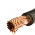
This circumstance is widely used in high-frequency technology: in some cases, capacitors are made simply in the form of printed circuit tracks, or even just two wires twisted together in polyethylene insulation. An ordinary noodle wire or cable also has a capacitance, and it increases with increasing length.
In addition to capacitance C, any cable also has a resistance R. Both of these physical properties are distributed along the length of the cable, and when transmitting pulse signals they work as an integrating RC chain, shown in Figure 2.

Figure 2.
In the figure, everything is simple: here is the circuit, here is the input signal, and here is the output signal. The impulse is distorted beyond recognition, but this is done on purpose, which is why the circuit was assembled. In the meantime, we are talking about the effect of cable capacitance on the pulse signal. Instead of a pulse, a “bell” like this will appear at the other end of the cable, and if the pulse is short, then it may not reach the other end of the cable at all, it may completely disappear.
Historical fact
Here it is quite appropriate to recall the story of how the transatlantic cable was laid. The first attempt in 1857 failed: telegraph dots and dashes (rectangular pulses) were distorted so that nothing could be made out at the other end of a 4,000 km long line.
A second attempt was made in 1865. By this time, the English physicist W. Thompson had developed a theory of data transmission over long lines. In light of this theory, the cable laying turned out to be more successful; signals were received.
For this scientific feat, Queen Victoria awarded the scientist a knighthood and the title of Lord Kelvin. This was the name of a small town on the coast of Ireland where the cable laying began. But this is just a word, and now let’s return to the last letter in the formula, namely, the dielectric constant of the medium ε.
A little about dielectrics
This ε is in the denominator of the formula, therefore, its increase will entail an increase in capacity. For most dielectrics used, such as air, lavsan, polyethylene, fluoroplastic, this constant is almost the same as that of vacuum. But at the same time, there are many substances whose dielectric constant is much higher. If an air condenser is filled with acetone or alcohol, its capacity will increase by 15...20 times.
But such substances, in addition to high ε, also have a fairly high conductivity, so such a capacitor will not hold a charge well; it will quickly discharge through itself. This harmful phenomenon is called leakage current. Therefore, special materials are being developed for dielectrics, which make it possible to provide acceptable leakage currents with high specific capacitance of capacitors. This is precisely what explains such a variety of types and types of capacitors, each of which is designed for specific conditions.
They have the highest specific capacity (capacity/volume ratio). The capacity of the “electrolytes” reaches up to 100,000 uF, operating voltage up to 600V. Such capacitors work well only at low frequencies, most often in power supply filters. Electrolytic capacitors are connected with correct polarity.
The electrodes in such capacitors are a thin film of metal oxide, which is why these capacitors are often called oxide capacitors. A thin layer of air between such electrodes is not a very reliable insulator, so a layer of electrolyte is introduced between the oxide plates. Most often these are concentrated solutions of acids or alkalis.
Figure 3 shows one such capacitor.

Figure 3. Electrolytic capacitor
To estimate the size of the capacitor, a simple matchbox was photographed next to it. In addition to the fairly large capacity, in the figure you can also see the tolerance as a percentage: no less than 70% of the nominal.
In those days when computers were large and were called computers, such capacitors were in disk drives (in modern HDD). The information capacity of such drives can now only cause a smile: 5 megabytes of information were stored on two disks with a diameter of 350 mm, and the device itself weighed 54 kg.
The main purpose of the supercapacitors shown in the figure was to remove magnetic heads from the working area of the disk during a sudden power outage. Such capacitors could store a charge for several years, which was tested in practice.
Below, we will suggest doing a few simple experiments with electrolytic capacitors to understand what a capacitor can do.
Non-polar electrolytic capacitors are produced for operation in alternating current circuits, but for some reason they are very difficult to obtain. To somehow get around this problem, conventional polar “electrolytes” are switched on counter-sequentially: plus-minus-minus-plus.
If a polar electrolytic capacitor is connected to an alternating current circuit, it will first heat up, and then there will be an explosion. Old domestic capacitors scattered in all directions, while imported ones have a special device that allows them to avoid loud shots. As a rule, this is either a cross notch on the bottom of the capacitor, or a hole with a rubber plug located there.
They really don't like high voltage electrolytic capacitors, even if the polarity is correct. Therefore, you should never put “electrolytes” in a circuit where a voltage close to the maximum for a given capacitor is expected.
Sometimes in some, even reputable forums, beginners ask the question: “The diagram shows a 470µF * 16V capacitor, but I have 470µF * 50V, can I install it?” Yes, of course you can, but reverse replacement is unacceptable.
The capacitor can store energy
A simple diagram shown in Figure 4 will help you understand this statement.

Figure 4. Circuit with capacitor
The main character of this circuit is an electrolytic capacitor C of a sufficiently large capacity so that the charge and discharge processes proceed slowly, and even very clearly. This makes it possible to observe the operation of the circuit visually using a regular flashlight light bulb. These flashlights have long given way to modern LED ones, but light bulbs for them are still sold. Therefore, it is very simple to assemble a circuit and conduct simple experiments.
Maybe someone will say: “Why? After all, everything is obvious, but if you also read the description...” There seems to be nothing to object to here, but any, even the simplest thing, remains in the head for a long time if its understanding came through the hands.
So, the circuit is assembled. How does it work?
In the position of switch SA shown in the diagram, capacitor C is charged from power source GB through resistor R in the circuit: +GB __ R __ SA __ C __ -GB. The charging current in the diagram is shown by an arrow with the index iз. The capacitor charging process is shown in Figure 5.

Figure 5. Capacitor charging process
The figure shows that the voltage across the capacitor increases along a curved line, called an exponential in mathematics. The charge current directly mirrors the charge voltage. As the voltage across the capacitor increases, the charging current becomes less. And only at the initial moment it corresponds to the formula shown in the figure.
After some time, the capacitor will charge from 0V to the voltage of the power source, in our circuit up to 4.5V. The whole question is how to determine this time, how long to wait, when will the capacitor charge?
Time constant "tau" τ = R*C
This formula simply multiplies the resistance and capacitance of a series-connected resistor and capacitor. If, without neglecting the SI system, we substitute the resistance in Ohms and the capacitance in Farads, then the result will be obtained in seconds. This is the time required for the capacitor to charge to 36.8% of the power source voltage. Accordingly, charging to almost 100% will require a time of 5* τ.
Often, neglecting the SI system, they substitute resistance in Ohms and capacitance in microfarads into the formula, then the time will be in microseconds. In our case, it is more convenient to obtain the result in seconds, for which you simply have to multiply microseconds by a million, or, more simply, move the decimal point six places to the left.
For the circuit shown in Figure 4, with a capacitor capacity of 2000 μF and a resistor resistance of 500 Ω, the time constant will be τ = R*C = 500 * 2000 = 1,000,000 microseconds or exactly one second. Thus, you will have to wait approximately 5 seconds until the capacitor is fully charged.
If, after the specified time, the switch SA is moved to the right position, the capacitor C will discharge through the light bulb EL. At this moment there will be a short flash, the capacitor will discharge and the light will go out. The direction of capacitor discharge is shown by an arrow with the index ip. The discharge time is also determined by the time constant τ. The discharge graph is shown in Figure 6.

Figure 6. Capacitor discharge graph
The capacitor does not pass direct current
An even simpler diagram shown in Figure 7 will help you verify this statement.

Figure 7. Circuit with a capacitor in a DC circuit
If you close switch SA, the light bulb will flash briefly, indicating that capacitor C has charged through the light bulb. The charge graph is also shown here: at the moment the switch is closed, the current is maximum, as the capacitor is charged, it decreases, and after a while it stops completely.
If the capacitor is of good quality, i.e. with a low leakage current (self-discharge), repeated closure of the switch will not lead to a flash. To get another flash, the capacitor will have to be discharged.
Capacitor in power filters
The capacitor is usually placed after the rectifier. Most often, rectifiers are made full-wave. The most common rectifier circuits are shown in Figure 8.
Figure 8. Rectifier circuits
Half-wave rectifiers are also used quite often, as a rule, in cases where the load power is insignificant. The most valuable quality of such rectifiers is their simplicity: just one diode and a transformer winding.
For a full-wave rectifier, the capacitance of the filter capacitor can be calculated using the formula
C = 1000000 * Po / 2*U*f*dU, where C is the capacitance of the capacitor μF, Po is the load power W, U is the voltage at the output of the rectifier V, f is the frequency of the alternating voltage Hz, dU is the amplitude of ripple V.
The large number in the numerator 1,000,000 converts the capacitance of the capacitor from system Farads to microfarads. The two in the denominator represents the number of half-cycles of the rectifier: for a half-wave rectifier, one will appear in its place
C = 1000000 * Po / U*f*dU,
and for a three-phase rectifier the formula will take the form C = 1000000 * Po / 3*U*f*dU.
Supercapacitor - ionistor
Recently, a new class of electrolytic capacitors has appeared, the so-called. In its properties it is similar to a battery, although with several limitations.
The ionistor is charged to the rated voltage within a short time, literally in a few minutes, so it is advisable to use it as a backup power source. In fact, the ionistor is a non-polar device; the only thing that determines its polarity is charging at the manufacturer. To prevent this polarity from being confused in the future, it is indicated with a + sign.
The operating conditions of ionistors play a big role. At a temperature of 70˚C at a voltage of 0.8 of the rated voltage, the guaranteed durability is no more than 500 hours. If the device operates at a voltage of 0.6 of the nominal voltage, and the temperature does not exceed 40 degrees, then proper operation is possible for 40,000 hours or more.
The most common application of an ionistor is in backup power supplies. These are mainly memory chips or electronic watches. In this case, the main parameter of the ionistor is low leakage current, its self-discharge.
The use of ionistors in conjunction with solar batteries is quite promising. This is also due to the non-criticality of the charge conditions and the practically unlimited number of charge-discharge cycles. Another valuable property is that the ionistor does not require maintenance.
So far I’ve managed to tell you how and where electrolytic capacitors work, mainly in DC circuits. The operation of capacitors in alternating current circuits will be discussed in another article -.
A capacitor (cap) is a small "battery" that charges quickly when there is voltage around it and quickly discharges back when there is not enough voltage to hold a charge.
The main characteristic of a capacitor is its capacity. It is indicated by the symbol C, its unit of measurement is Farad. The larger the capacitance, the more charge the capacitor can hold at a given voltage. Also than more capacity, the less charging and discharging speed.
Typical values used in microelectronics: from tens of picofarads (pF, pF = 0.000000000001 F) to tens of microfarads (μF, μF = 0.000001). The most common types of capacitors are ceramic and electrolytic. Ceramic ones are smaller in size and usually have a capacitance of up to 1 µF; they don’t care which of the contacts will be connected to the plus and which to the minus. Electrolytic capacitors have capacitances from 100 pF and they are polar: a specific contact must be connected to the positive. The leg corresponding to the plus is made longer.
A capacitor consists of two plates separated by a dielectric layer. The plates accumulate charge: one is positive, the other is negative; thereby creating tension inside. The insulating dielectric prevents internal voltage from turning into internal current, which would equalize the plates.
Charging and discharging
Consider this diagram:

While the switch is in position 1, voltage is created on the capacitor - it charges. Charge Q on the plate at a certain point in time is calculated by the formula:

C- capacity, e- exponent (constant ≈ 2.71828), t- time from the start of charging. The charge on the second plate is always exactly the same in value, but with the opposite sign. If the resistor R remove, only a small resistance of the wires will remain (this will become the value R) and charging will occur very quickly.
By plotting the function on a graph, we get the following picture:

As you can see, the charge does not grow uniformly, but inversely exponentially. This is due to the fact that as the charge accumulates, it creates more and more reverse voltage Vc, which “resists” V in.
It all ends with this Vc becomes equal in value V in and the current stops flowing altogether. At this point the capacitor is said to have reached its saturation point (equilibrium). The charge reaches its maximum.
Remembering Ohm's Law, we can depict the dependence of the current in our circuit when charging a capacitor.

Now that the system is in equilibrium, put the switch in position 2.

The capacitor plates have charges of opposite signs, they create voltage - a current appears through the load (Load). The current will flow in the opposite direction compared to the direction of the power source. Discharge will also occur in the opposite way: at first the charge will be lost quickly, then, with a drop in the voltage created by it, slower and slower. If for Q 0 designate the charge that was on the capacitor initially, then:
These values on the graph look like this:

Again, after some time the system will come to a state of rest: all charge will be lost, the voltage will disappear, and the current flow will stop.
If you use the switch again, everything will start in a circle. So the capacitor does nothing other than break the circuit when the voltage is constant; and “works” when the voltage changes suddenly. This property determines when and how it is used in practice.
Application in practice
Among the most common in microelectronics are the following patterns:
Backup capacitor (bypass cap) - to reduce supply voltage ripples
Filter capacitor - to separate the constant and changing voltage components, to isolate the signal
Reserve capacitor
Many circuits are designed to provide constant, stable power. For example, 5 V. The power supply supplies it to them. But ideal systems do not exist, and in the event of a sudden change in the current consumption of the device, for example, when a component is turned on, the power source does not have time to “react” instantly and a short-term voltage drop occurs. In addition, in cases where the wire from the power source to the circuit is long enough, it begins to act as an antenna and also introduce unwanted noise into the voltage level.

Typically, the deviation from the ideal voltage does not exceed a thousandth of a volt, and this phenomenon is absolutely insignificant when it comes to powering, for example, LEDs or an electric motor. But in logic circuits, where the switching of logic zero and logic one occurs based on changes in small voltages, power supply noise can be mistaken for a signal, which will lead to incorrect switching, which, like a domino effect, will put the system in an unpredictable state.
To prevent such failures, a backup capacitor is placed directly in front of the circuit

At moments when the voltage is full, the capacitor is charged to saturation and becomes a reserve charge. As soon as the voltage level on the line drops, the backup capacitor acts as a fast battery, releasing the previously accumulated charge to fill the gap until the situation returns to normal. Such assistance to the main power source occurs a huge number of times every second.
If we think from a different point of view: the capacitor extracts the alternating component from the direct voltage and, passing it through itself, takes it from the power line to the ground. This is why the backup capacitor is also called "bypass capacitor".
As a result, the smoothed voltage looks like this:

Typical capacitors used for these purposes are ceramic capacitors with a nominal value of 10 or 100 nF. Large electrolytic cells are poorly suited for this role, because they are slower and will not be able to quickly release their charge in these conditions, where the noise is of high frequency.
In one device, backup capacitors can be present in many places: in front of each circuit, which is an independent unit. For example, Arduino already has backup capacitors that ensure stable operation of the processor, but before powering the LCD screen connected to it, you must install your own.
Filter capacitor
A filter capacitor is used to remove the signal from the sensor, which transmits it in the form of a varying voltage. Examples of such sensors are a microphone or an active Wi-Fi antenna.
Let's look at the connection diagram for an electret microphone. The electret microphone is the most common and ubiquitous: this is the type used in mobile phones, computer accessories, and public address systems.

The microphone requires power to operate. In a state of silence, its resistance is high and amounts to tens of kiloohms. When it is exposed to sound, the gate of the field-effect transistor built inside opens and the microphone loses its internal resistance. The loss and restoration of resistance occurs many times every second and corresponds to the phase of the sound wave.
At the output, we are only interested in the voltage at those moments when there is sound. If there were no capacitor C, the output would always be additionally affected by the constant supply voltage. C blocks this constant component and allows only deviations, which correspond to the sound, to pass through.
The audible sound, which is of interest to us, is in the low-frequency range: 20 Hz - 20 kHz. In order to isolate the sound signal from the voltage, and not the high-frequency power noise, as C A slow electrolytic capacitor with a nominal value of 10 µF is used. If a fast capacitor, say 10 nF, were used, non-audio signals would pass through to the output.
Note that the output signal is supplied as a negative voltage. That is, when the output is connected to ground, current will flow from the ground to the output. Peak voltage values in the case of a microphone are tens of millivolts. To reverse the voltage and increase its value, the output Vout usually connected to an operational amplifier.
Connection of capacitors
If compared with the connection of resistors, the calculation of the final value of the capacitors looks the other way around.
When connected in parallel, the total capacitance is summed up:

When connected in series, the final capacity is calculated using the formula:


If there are only two capacitors, then with a series connection:
In the particular case of two identical capacitors, the total capacitance of the series connection is equal to half the capacitance of each.
Limit characteristics
The documentation for each capacitor indicates the maximum permissible voltage. Exceeding it can lead to breakdown of the dielectric and explosion of the capacitor. For electrolytic capacitors, polarity must be observed. Otherwise, either the electrolyte will leak out or there will be an explosion again.
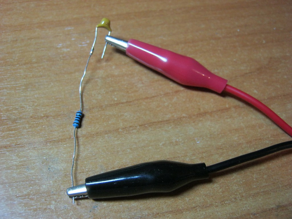
Constant voltage and set the voltage on his crocodiles to 12 Volts. We also take a 12 Volt light bulb. Now we insert a capacitor between one probe of the power supply and the light bulb:
Nope, it doesn't burn.
But if you do it directly, it lights up:

This begs the conclusion: DC current does not flow through the capacitor!
To be honest, at the very initial moment of applying voltage, the current still flows for a fraction of a second. It all depends on the capacitance of the capacitor.
Capacitor in AC circuit
So, to find out whether AC current is flowing through the capacitor, we need an alternator. I think this frequency generator will do just fine:

Since my Chinese generator is very weak, instead of a light bulb load we will use a simple 100 Ohm one. Let’s also take a capacitor with a capacity of 1 microfarad:

We solder something like this and send a signal from the frequency generator:
Then he gets down to business. What is an oscilloscope and what is used with it, read here. We will use two channels at once. Two signals will be displayed on one screen at once. Here on the screen you can already see interference from the 220 Volt network. Do not pay attention.

We will apply alternating voltage and watch the signals, as professional electronics engineers say, at the input and output. Simultaneously.
It will all look something like this:

So, if our frequency is zero, then this means constant current. As we have already seen, the capacitor does not allow direct current to pass through. This seems to have been sorted out. But what happens if you apply a sinusoid with a frequency of 100 Hertz?
On the oscilloscope display I displayed parameters such as signal frequency and amplitude: F is the frequency Ma – amplitude (these parameters are marked with a white arrow). The first channel is marked in red, and the second channel in yellow, for ease of perception.

The red sine wave shows the signal that the Chinese frequency generator gives us. The yellow sine wave is what we already get at the load. In our case, the load is a resistor. Well, that's all.
As you can see in the oscillogram above, I supply a sinusoidal signal from the generator with a frequency of 100 Hertz and an amplitude of 2 Volts. On the resistor we already see a signal with the same frequency (yellow signal), but its amplitude is some 136 millivolts. Moreover, the signal turned out to be somewhat “shaggy”. This is due to the so-called ““. Noise is a signal with small amplitude and random voltage changes. It can be caused by the radio elements themselves, or it can also be interference that is caught from the surrounding space. For example, a resistor “makes noise” very well. This means that the “shaggyness” of the signal is the sum of a sinusoid and noise.
The amplitude of the yellow signal has become smaller, and even the graph of the yellow signal shifts to the left, that is, it is ahead of the red signal, or in scientific language, it appears phase shift. It is the phase that is ahead, not the signal itself. If the signal itself was ahead, then we would have the signal on the resistor appear in time earlier than the signal applied to it through the capacitor. The result would be some kind of time travel :-), which, of course, is impossible.
Phase shift- This difference between the initial phases of two measured quantities. In this case, tension. In order to measure the phase shift, there must be a condition that these signals same frequency. The amplitude can be any. The figure below shows this very phase shift or, as it is also called, phase difference:

Let's increase the frequency on the generator to 500 Hertz

The resistor has already received 560 millivolts. The phase shift decreases.
We increase the frequency to 1 KiloHertz

At the output we already have 1 Volt.
Set the frequency to 5 Kilohertz

The amplitude is 1.84 Volts and the phase shift is clearly smaller
Increase to 10 Kilohertz

The amplitude is almost the same as at the input. The phase shift is less noticeable.
We set 100 Kilohertz:

There is almost no phase shift. The amplitude is almost the same as at the input, that is, 2 Volts.
From here we draw profound conclusions:
The higher the frequency, the less resistance the capacitor has to alternating current. The phase shift decreases with increasing frequency to almost zero. At infinitely low frequencies its magnitude is 90 degrees orπ/2 .
If you plot a slice of the graph, you will get something like this:

I plotted voltage vertically and frequency horizontally.
So, we have learned that the resistance of a capacitor depends on frequency. But does it only depend on frequency? Let's take a capacitor with a capacity of 0.1 microfarad, that is, a nominal value 10 times less than the previous one, and run it again at the same frequencies.
Let's look and analyze the values:


Carefully compare the amplitude values of the yellow signal at the same frequency, but with different capacitor values. For example, at a frequency of 100 Hertz and a capacitor value of 1 μF, the amplitude of the yellow signal was 136 millivolts, and at the same frequency, the amplitude of the yellow signal, but with a capacitor of 0.1 μF, was already 101 millivolts (in reality, even less due to interference ). At a frequency of 500 Hertz - 560 millivolts and 106 millivolts, respectively, at a frequency of 1 Kilohertz - 1 Volt and 136 millivolts, and so on.
From here the conclusion suggests itself: As the value of a capacitor decreases, its resistance increases.
Using physical and mathematical transformations, physicists and mathematicians have derived a formula for calculating the resistance of a capacitor. Please love and respect:

Where, X C is the resistance of the capacitor, Ohm
P - constant and equals approximately 3.14
F– frequency, measured in Hertz
WITH– capacitance, measured in Farads
So, put the frequency in this formula at zero Hertz. A frequency of zero Hertz is direct current. What will happen? 1/0=infinity or very high resistance. In short, a broken circuit.
Conclusion
Looking ahead, I can say that in this experiment we obtained (high-pass filter). Using a simple capacitor and resistor, and applying such a filter to the speaker somewhere in the audio equipment, we will only hear squeaky high tones in the speaker. But the bass frequency will be dampened by such a filter. The dependence of capacitor resistance on frequency is very widely used in radio electronics, especially in various filters where it is necessary to suppress one frequency and pass another.
 How to quickly and correctly strip a wire of insulation
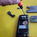 Making a wireless doorbell with your own hands Making a doorbell from an old mobile phone
 Schottky diodes reference book imported markings