Kacher eyebrow with self-powering generator circuit. What is a Brovin Kacher? Let's figure it out and make a kacher together. So, what do we need to assemble a powerful Brovin kacher?
The idea to modify the well-known Brovin casser circuit came to me after some of my friends could not start the casser due to the lack of a power source with a voltage of 12 Volts or higher, which is indicated on the standard circuit. To get around this obstacle, I decided to combine a quality generator circuit and a blocking generator, which allowed me to lower the supply voltage to 5-6 Volts (can be raised to 15 Volts). The quality diagram is shown below.
List of required parts:
- any ferrite ring (height 0.7 cm, outer diameter 1.5-2 cm, inner diameter 0.5-0.7 cm; dimensions are not critical);
- 2 resistors 1 kOhm 0.5 W;
- trimming resistor 220 Ohm 0.25 W;
- 2 transistors KT805;
- 2 radiators for transistors4
- 1 rectifier diode 1 A;
- capacitor 10000 uF 50 V;
- winding wire 0.25 mm;
- single-wire copper wire 1.5 sq. mm (for primary coil);
- wire 0.5 sq. mm single-core stranded (for connecting all parts together);
- a piece of plastic (not metal-plastic!) pipe 30 cm from a regular water supply (0.5"") and a plank for making a stand.
The primary coil is wound with a single-wire wire (a copper core from a VVG cable, for example) on any round mandrel with a diameter of 5-7 cm (mine is 5 cm), 4 turns, the mandrel is removed after making the coil. The height of the primary should be 10-15 cm, i.e. The primary is then stretched to the required length. The secondary is wound 800-1400 turns in one layer with a thin wire on a pipe. Next, everything is assembled according to the diagram. Structurally, the primary should be around the bottom of the secondary.

Setting up the circuit is extremely simple and is done by adjusting R1. If the circuit does not work, swap the ends of the primary.
It is imperative to attach radiators to transistors, since the former do not heat up slightly.

The functionality is checked by placing an energy-saving light bulb or an indicator screwdriver at the upper end of the secondary. They burn from a distance. Also, when the secondary is touched by metal objects, sparks occur between them and the coil. With a large number of turns of the secondary, electrical discharges may occur directly into the air.
List of radioelements
| Designation | Type | Denomination | Quantity | Note | Shop | My notepad |
|---|---|---|---|---|---|---|
| VT1, VT2 | Bipolar transistor | KT805AM | 2 | To notepad | ||
| D1 | Rectifier diode | 1 | Any for a current of at least 1 A | To notepad | ||
| C1 | Electrolytic capacitor | 10000uF 50V | 1 | To notepad | ||
| R1 | Variable resistor | 220 Ohm | 1 | To notepad | ||
| R2, R3 | Resistor | 1 kOhm | 2 | To notepad | ||
| Bat1 | Battery | 1 | 5-6 V | To notepad | ||
| S1 | Switch | 1 |
High voltage entertainment provides a lot of fun and little benefit. This means we definitely need to collect something like this. Probably the simplest Tesla coil power supply circuit is the Brovin kacher. It can be assembled on a lamp, a regular or field-effect transistor. The circuit is unpretentious - it works without configuration.
There are many legends around the catcher Brovin because of the non-standard connection diagram of the transistor, which operates in extreme modes - it breaks down inside itself and is immediately restored. We will not describe a dry theory, we only need the result.
I will give two diagrams for connecting the camera.
For NPN transistor:

For field effect transistor:

It was decided to assemble the second circuit on a field-effect transistor because There were no other powerful transistors at hand.
My circuit consisted of: resistor R2 - 2 kOhm, resistor R1 - 10 kOhm, field-effect transistor VT1 - IRLB8721 (was attached to a powerful radiator because it gets very hot). The circuit was powered by 12 Volts.


I wound the secondary coil on a sewer pipe with a thin wire. Approximately 800 turns. I clamped the pipe into a screwdriver and wound as much as it would fit.

The primary winding was made with 1.5 turns of thick copper wire. It is better to make the winding diameter larger than the secondary one. It is better to select the position and number of turns experimentally in order to select the maximum voltage output.

An increase in discharge power can be achieved not only by tuning the antenna and selecting resistors, but also by connecting a powerful choke with a large capacitor to the power input. Increasing the supply voltage proportionally increases the length of the discharges.

The ketcher turned out to be not super powerful, but it was enough for pampering. In the air it hit up to 7 mm. I confidently lit gas-discharge lamps 20 cm from the winding and produced beautiful coronary discharges in incandescent lamps.


It was decided to test the first circuit using the KT805AM transistor with the same resistor values as for the field one (2 kOhm and 10 kOhm). Surprisingly, the power of the discharges doubled, and a coronal discharge burned steadily in the air. Since it was so bad, I designed the installation as a finished device.
In this review, we present to your attention a diagram of the assembly of a Brovin kacher or a Tesla transformer.
We will need:
- winding wire;
- NPN transistor;
- 47 kOhm resistor;
- Light-emitting diode;
- plastic or polypropylene pipe 140 mm long and 22 mm in diameter;

There is no need to buy a winding wire, since it is present in every charger or power supply. If you decide to remove the wire from the power supply, then note that it is wound on a “W” or “E” shaped transformer. One of the coils on the transformer has a thick, rather short wire. The wire on the second coil is much thinner and there is much more of it. In any case, the transformer must be disassembled to get to the wire. This can be done by tapping the housing with a hammer, due to which the varnish will gradually break and the transformer will fall apart.


Next, you need to remove the layer of electrical tape on the wires and release the winding wire.


Let's start with the coil. First you need to find the length of the wire of one turn. To do this, multiply the number Pi (3.14) by the outer diameter of the pipe. If you use a pipe with a diameter of 22 mm, the result will be 6.9 cm.

Now take the length of the turn and multiply it by the required number of turns. In the author's case, there will be 450 of them. The result is that we need 31 m of wire to make a coil of 450 turns on the pipe that the author uses.

Next, measure a distance of one meter on the desktop. This is necessary to accurately mark the wire.


We wrap the coil. This can be done manually, but you can also build a simple unit using a screwdriver or drill and make the winding easier.


Next, we take a 47 kOhm resistor, one LED, a coil and an NPN transistor. The author does not recommend using small transistors, since they cannot withstand high voltages or loads. The best of all the transistors that the author used was the BD241 transistor.

Let's start assembling the circuit itself, which the author does on BreadBoard for greater clarity.

The diagram shows that the plus passes through the resistor and goes to the transistor, but also goes to the coil, from where it also goes to the transistor. Therefore, the first thing we do is connect the transistor.
The pinout of the transistor is simple. We represent it in the figure below, where B means base, C is collector

We connect the resistor to the base leg.

The second plus should go to the coil, which in this case is a simple wire with five turns around the wire that was wound at the beginning. Connect one end of the wire to the collector. We connect the second end of the wire to one contact from the coil.

We connect the second contact from the coil directly to the positive.
Preface
This spring, I was faced with the task of creating a set of generators to test the stability of equipment under conditions of strong electrical discharges. In addition to the transistor-based HF generators that are familiar to me, which provide good HF field strength nearby, I needed a small high-voltage source. This is where I remembered the quality device of the Soviet radio engineer Vladimir Ilyich Brovin - a simple device that allows me to get the high voltage I need.
I assembled my first kacher back in the early 2000s. It was a fairly powerful device almost one meter high, producing a dense beam of corona discharges. It was a dangerous thing... Hair began to move a couple of meters from it... But now I need a compact, small coil that is safe to use. After examining the materials and parts I had, I got to work.
Device diagram
The quality circuit has reached our times practically unchanged and is a blocking oscillator on a single transistor. Currently, there are many variants of circuits for this device assembled using lamps, bipolar and field-effect transistors, but I settled on the simplest “classical” circuit.

“Classic” scheme of Brovin’s quality
Parts and materials
The device is based on two main elements - an inductively coupled coil and a transistor for generating oscillations. The transistor was chosen D1761(the first one that caught my eye and had the required parameters). As a coil frame, I used a piece of polypropylene plastic pipe with a diameter of 32 mm and a length of 140 mm. In addition, in the bins there was a coil with PEV-2 wire, 0.15 mm in diameter, which I used in the manufacture of the quality device.
Assembling the device
Stepping back 20 mm from the end of the tube, I wound 650 turns of wire (winding - turn to turn in one layer, without overlaps). In this case, the length of the coil winding L2 was 105 mm.
I soldered the mounting wires to the ends of the wire and secured them inside the tube to prevent damage to the winding. The entire winding was covered with two layers of acrylic varnish. I soldered a steel needle to the upper terminal of the coil and brought it out through a decorative plastic plug. I secured the coil body on the circuit board for easy setup and placement of the coil. L1.
![]()
Brovin quality components![]()
![]()
Reel L1 I made it from a copper busbar, 3 mm wide. It is wound on a mandrel D 45 mm, only 5 turns with a small pitch. Here you need to remember that the direction of winding the turns is the same as that of coil L2. If the winding directions do not coincide, the generator will consume current, but there will be no high voltage at the output!
To connect the L1 coil to the circuit, I installed a screw connector. It turned out simple and convenient.
Since the pump circuit contains only 5 parts, I assembled it using a hinged installation, placing the parts on the radiator body.

Device setup
A correctly and carefully assembled generator from serviceable components almost always starts working. To obtain the maximum voltage, you can try to change the position and number of turns of the L1 coil, focusing on the size of the streamer and the current consumed. In my case, with a supply voltage of 24 volts, the coil consumes 0.85 A. For my task, this is optimal. In some cases, it may be necessary to select resistors in the base circuit.

Since my streamer is not very large, to visually indicate the operation of the coil and the presence of high voltage, I added a small neon light bulb to the body of the coil.

Conclusion
The Brovin Kacher is an easy-to-replicate and interesting device for studying high-voltage discharges in various environments. The very principle of its operation is interesting and mysterious... After all, the voltages generated by the high-voltage coil, and these are thousands and tens of thousands of volts, do not damage the transistor, although they are directly applied to the base of this semiconductor device.
In principle, there is a scientific explanation for this mystery (and more than one), but still, the very principle of operation of the device remains a subject of debate among scientists and experimenters, as well as enthusiasts engaged in the search for Free Energy and studying the legacy of Nikola Tesla. Perhaps you will be the one to solve this riddle...
Attention! The site administration is not responsible for the content of methodological developments, as well as for the compliance of the development with the Federal State Educational Standard.
- Participant: Pishchulin Andrey Alexandrovich
- Head: Truntaeva Svetlana Yurievna
Introduction
At least once in our lives, we hear on TV or on the Internet about the great genius Nikola Tesla and his coil, which can transmit electricity through the air. But no one thought that at home you could assemble a similar device called the Brovin Kacher. In my work I want to show how you can use electrical appliances that are not connected to the network, and I will prove that this can be done at home without much expense.
Relevance The topic is due to the fact that the problem of finding clean energy in the 21st century is acute. In the modern world, humanity needs electricity every day. It is needed both by large enterprises and in everyday life. A lot of money is spent on its production. And that's why electricity bills are rising every year.
Object of study: physical phenomenon of contactless energy transfer.
Subject of study: a device that can transmit electricity wirelessly.
Hypothesis: Kacher Brovina can be assembled at home with minimal cost.
Target: make a working model of the Brovin Kacher and consider the possibilities of its practical application.
Tasks:
- study reference and scientific literature on this topic;
- consider the device, principle of operation and application of the Brovin kacher;
- create a working model of the Brovin quality player;
- analyze the knowledge gained on this topic.
Research methods:
- working with methodological literature
- comparative analysis
- observation
- experiment
Chapter I. Theoretical part
1.1. The device and principle of operation of the Brovin Kacher
The Brovin Kacher was invented in 1987 by Soviet radio engineer Vladimir Ilyich Brovin as an element of an electromagnetic compass. Engineer Brovin V.I. Higher education – graduated from the Moscow Institute of Electronic Technology in 1972. In 1987, he discovered inconsistencies with generally accepted knowledge in the operation of the electronic circuit of the compass he created and began to study them. He made many inventions at home. One of them is Kacher Brovina.
Let's take a closer look at what kind of device this is. Brovin's kacher is a type of generator assembled on a single transistor and operating, according to the inventor, in abnormal mode. The device exhibits mysterious properties that date back to the research of Nikola Tesla. They do not fit into any of the modern theories of electromagnetism. Apparently, Brovin's kacher is a kind of semiconductor spark gap in which the discharge of electric current passes through the crystalline base of the transistor, bypassing the stage of formation of an electric arc (plasma). The most interesting thing about the operation of the device is that after a breakdown, the transistor crystal is completely restored. This is explained by the fact that the operation of the device is based on reversible avalanche breakdown, in contrast to thermal breakdown, which is irreversible for a semiconductor. However, only indirect statements are given as evidence of this mode of operation of the transistor. No one, except the inventor himself, has studied the operation of the transistor in the described device in detail. So these are just assumptions by Brovin himself. So, for example, to confirm the “black” mode of operation of the device, the inventor cites the following fact: they say, no matter what polarity the oscilloscope is connected to the device, the polarity of the pulses shown by it will always be positive.
Maybe kacher is a type of blocking generator? There is also such a version. After all, the electrical circuit of the device strongly resembles an electrical pulse generator. Nevertheless, the author of the invention emphasizes that his device has a non-obvious difference from the proposed circuits. It provides an alternative explanation for the occurrence of physical processes inside the transistor. In a blocking oscillator, the semiconductor periodically opens as a result of the flow of electric current through the feedback coil of the base circuit. In quality, the transistor must be permanently closed in a so-called non-obvious way (since the creation of an electromotive force in the feedback coil connected to the base circuit of the semiconductor can still open it). In this case, the current generated by the accumulation of electrical charges in the base zone for further discharge, at the moment the threshold voltage value is exceeded, creates an avalanche breakdown. However, the transistors used by Brovin are not designed to operate in avalanche mode. A special series of semiconductors has been designed for this purpose. According to the inventor, it is possible to use not only bipolar transistors, but also field-effect and radio tubes, despite the fact that they have fundamentally different physics of operation. This forces us to focus not on research on the transistor itself in the quality, but on the specific pulse mode of operation of the entire circuit. In fact, Nikola Tesla was engaged in these studies.
Kacher Brovina is an original version of an electromagnetic oscillation generator. It can be assembled using various active radioelements. Currently, when assembling it, field-effect or bipolar transistors are used, less often radio tubes (triodes and pentodes). Kacher is a reactivity pump, as the author of the invention, Vladimir Ilyich Brovin, himself deciphered this abbreviation. The Brovin Kacher is powered by a modified 12 V, 2 A network adapter and consumes 20 W. It converts an electrical signal into a 1 MHz field with an efficiency of 90%. One of the parts of this device is a plastic pipe 80x200 mm. The primary and secondary windings of the resonator are wound on it. The entire electronic part of the device is located in the middle of this pipe. This circuit is completely stable, it can work for hundreds of hours without interruption. The Brovin Kacher with self-powering is interesting in that it is capable of lighting unconnected neon lamps at a distance of up to 70 cm.
1.2. Areas of use
The widespread practical application of new devices and products operating on the basis of this new physical phenomenon will make it possible to obtain a very significant economic, scientific and technical effect in various spheres and areas of human activity.
Let's consider the areas of application of this device:
1. New relays and magnetic starters based on the widespread use of kacher technology:
- can lead to a reduction in energy costs and an increase in production efficiency in general, which together will provide a very significant economic effect in the country’s economy;
2. Devices that illuminate fluorescent lamps (fluorescent lamps) not from 220 V, as now, but using KACHER technology products, from a supply voltage of 5 to 10 V:
- this will significantly reduce the level of fire and explosion hazards
3. Devices that provide the possibility of not serial (currently used), but parallel connection of individual solar battery elements:
- will significantly increase the reliability, durability and efficiency of their operation, as well as obtain a significant economic effect from their use;
4. Devices for inductive transmission of control information and energy between different traffic lights located on different sides of the intersection and included in one traffic light object (without the use of electrical wires currently used for this, with large labor costs for their installation):
- will save energy and costs.
1.3. Negative impact
Despite the positive aspects of using this device, one cannot fail to note its negative impact. While performing this practical work, I noticed that due to the strong electromagnetic field created near the camera, cell phones, cameras, and tablets fail. And here I thought that in addition to the positive aspects, this device has a negative effect, including on the human body. After reading the literature on this issue, I found out that a strong electromagnetic field has a negative effect on the human nervous system. Staying near a working device for a long time causes a headache, and upon close contact, a slight aching pain in the muscles of the arms. In addition, as it turned out, the kacher can emit ozone, which we can feel by the corresponding smell.
Also, do not touch the discharges with your hands; due to the high frequency, a small burn may remain on the skin. Thus, we can conclude that when working with this device it is necessary to follow the safety rules:
- Do not try to touch the discharges with your hands. The pain, if there is any, will not be severe, but you are guaranteed a burn.
- Keep pets away from the device.
- Keep mobile phones and other electronics away from the device.
- You should not stay near the switched on device for a long time.
Chapter II. Practical part
2.1. Assembling the Brovin quality camera installation
Let's consider the stages of assembling this device at home.
Basic elements of Kacher:
- inductor (secondary winding);
- inductor (primary winding);
- pay.
- frame
The diagram that I followed during assembly is as follows:

Installation details:
- Polyvinyl chloride (PVC) pipe with a diameter of at least 25 mm and a length of 30 cm (the glow range of the light bulbs will depend on this). I used a pipe with a diameter of about 55 mm.
- To make the secondary winding of the kacher, I used copper wire coated with a double layer of varnish and 0.20 mm in diameter. It should be wound on the pipe, at least 1500 turns. (My copy of the kacher has about 2000 turns wound on it.) Every few centimeters I applied glue to fresh turns, otherwise the winding might get lost and tangled.
- To make the primary winding, I needed a copper wire with a diameter of 0.5 cm, which must be wound around the secondary coil. It is necessary to make about 4 turns. We wind all the windings in one direction! We install and secure the pipe with the winding on plywood or a board, stretch the primary winding by 1/3 of the secondary. The windings must not touch! Then we fuse a metal wire the size of a sewing needle into the pipe from above and solder the end of the winding to it. Next, we screw the radiator for the transistor to the platform next to the coils, coat the base with heat-conducting paste and screw the transistor to the radiator with a metal socket.
To make the board I needed the following radio components:
- throttle,
- non-polar capacitor (1000 v 3000 μ F),
- 2 resistors (2.2 kOhm and 150 Ohm),
- NPN transistor, the more powerful the better (they can be found in a regular PC power supply or on the board of old tube TVs).
Everything is mounted as shown in the diagram (Fig. 1). Solder the power wires.

This device must be connected to a power supply with a voltage from 12 to 38 v, which I also designed myself (Fig. 3)

Checking the quality is carried out by placing a fluorescent light bulb on the secondary winding; if the connection is correct, it will light up. When the secondary winding is touched by a metal object, there will be a discharge between them. If the kacher does not work, then you need to check whether the circuit is assembled correctly or try changing the ends of the primary winding.
2.2. Effects observed during the operation of the Brovin quality camera
Let's consider the effects observed during the work of Kacher Brovin, which I constructed at home.
- We bring a fluorescent lamp to the secondary winding, we see that it lights up. (Fig. 4) If you bring a gas-discharge lamp to the kacher, it also begins to glow. (Fig. 5) The same effect is observed with other similar lamps. Also in a regular incandescent lamp you can see the so-called glow discharge. (Fig. 6)


- During operation, the kacher creates beautiful effects associated with the formation of various types of gas discharges - a set of processes that occur when an electric current flows through a substance in a gaseous state. Brovin's quality ranks:
- Streamer (from English Streamer) - dimly glowing thin branched channels that contain ionized gas atoms and free electrons split off from them. Streamer - visible ionization of air (glow of ions) created by an explosive - Kacher field. (Fig. 7)

- Arc discharge occurs in many cases. For example, with sufficient transformer power, if a grounded object is brought close to its terminal, an arc may light up between it and the terminal. Sometimes you need to directly touch the terminal with an object and then stretch the arc, moving the object to a greater distance. (Fig. 8)

Conclusion
Kacher Brovina is an original version of an electromagnetic oscillation generator. In my work, I proved that it is possible to make a working model of a kacher at home, and also considered the possibilities of its practical application. I would like to note that my work in this direction is not finished. In the future, I want to make a Brovin kacher with audio modulation. To do this, you need to complicate the circuit a little by adding two resistors and a transistor. (Fig. 9) Thus, we will be able to play music through the power supply circuit of the camera. In practice it looks beautiful and interesting.

As a result of the research carried out in this work, we can conclude that the Brovin Kacher is a simple device to manufacture and configure. With which you can demonstrate many beautiful and spectacular experiments. During the operation of the coil, we observed two types of discharges.
Analyzing all of the above, we can say that Kacher Brovina can be successfully used in alternative energy, for example, in devices for generating free electricity using permanent magnets.
In conclusion, it is necessary to emphasize the following: the creation of new technologies based on the described physical phenomenon can give Russia very significant advantages over other countries. Since, having carried out in the near future all the necessary studies of this physical phenomenon and developed a wide range of new devices and products operating on its basis and intended for wide practical application in various fields and spheres of human activity, Russia can make a new qualitative leap in its further technological development . The introduction of Russian know-how will radically change the entire energy infrastructure and society as a whole - when a new method of generating energy is suddenly discovered and experimentally confirmed.
 How to quickly and correctly strip a wire of insulation
 Making a wireless doorbell with your own hands Making a doorbell from an old mobile phone
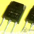 Schottky diodes reference book imported markings