Doorbell ringing from an old cell phone. Making a wireless doorbell with your own hands Making a doorbell from an old mobile phone
Old push-button mobile phones are long outdated and almost out of use. However, there are many ways to give such a phone a second “life” rather than sending it to scrap or a landfill. Today we will consider one of these ways to put this miracle of the 90s into action. Recently they brought me a whole package of old and broken phones. For parts. In this pile there were also modern smartphones with dead batteries, drowned and broken, and there were also completely working push-button phones, which they decided to get rid of only because of their unpresentable appearance today. And just at almost the same time, my doorbell, which I had assembled with my own hands and served flawlessly for many years, “cracked up.” This circumstance prompted me to think; why not repurpose an old work phone to replace your front doorbell. And then - there are more advantages from such a call than from a regular one: in addition to the pleasure of assembling and then using something made with your own hands, you can put sounds and melodies on the signal as you wish, the volume can be adjusted, and so on... By choosing a push-button telephone with a music player and powerful speakers, I got to work.
Will need
- Push-button telephone with mp3 player.
- Soldering iron (with flux and solder).
- Copper wires.
- Screwdrivers (flat and Phillips).
- Secondary glue.
- Insulation (insulating tape or thermal tubes).
- Stationery knife.
- Scissors.
Making a doorbell from an old cell phone
So, let's disassemble the phone. We take out the battery, unscrew the screws (if any), and use a flat-head screwdriver to remove all the parts fastened with latches.

Now we find the “play/pause” button in the place where the player control panel was, and disassemble the button so that it does not interfere with the future soldering of thin wires to its contacts.


Solder to the wiring contacts.

It is necessary to immediately grab them with a second glue to the base (to the microcircuit) so that they do not fall off in the future, because the contacts are small and, accordingly, the soldering area is too. The work is quite intricate and painstaking, but that makes it all the more interesting! By the way; If your phone did not have separate player buttons, you can use the “OK” button. If everything went well, we put everything back together. We install all the components and the housing in place, not forgetting to bring out the soldered wires.

Now turn on the phone. We load any sound you need onto the signal (for example, I put a bird). Select the player from the menu.


Don’t forget to turn off the melody repeat (if you had it turned on), otherwise when you press the call button, it will play it until the battery runs out, or someone turns it off.

Next, you need to find some kind of contactor (button) for the wires brought out from the player.

You will also need a double wire of the required length - from the button, which will be outside, to the telephone located at home. My problem with the button resolved itself: I just used the old one from an old broken bell.
Retro apartment bell made from old trash
Every radio amateur knows that before assembling a circuit, you need to take care of the structure’s body, otherwise the circuit will turn out “accurate to a printed circuit board.” I was once going through a bunch of old junk, among which there was a pocket for IDE hard drives, and I remembered this old saying from radio amateurs. In addition, an old telephone set with a rotary dialer, a broken switch for lighting in the apartment, and a bunch of other rubbish that had nothing to do with the case were discovered. From all these antiquities and unnecessary things, which, in truth, it’s time to just throw them in a landfill, we got a pretty neat apartment bell powered by 220V.
Idea

Materials and tools
1.Boxing (pocket) for IDE drives.
2. An old telephone with a mechanical bell (TA-58).
4. Resistor 3..6 kOhm, 40 cm of flexible mounting wire, two racks for wall-mounted mounting (you can do without racks), a piece of foil fiberglass.
5. Knife, soldering iron, drill, drill bits, screws (nuts, washers) M3, hacksaw (optional).


The beauty of the mechanical ringing system of older landline phones is that they are globally flat and have a low height, which depends mainly on the size of the ringing cups (). In this case, the depth of the IDE pocket drawer turned out to be 2 mm less than the height of the bell, so the protruding lower parts had to be recessed inside the lid by cutting a rectangular hole in the lid () and at the same time drilling three holes to attach the bell itself in the drawer. In addition, to improve the appearance, it is recommended to remove the handle from the drawer itself. The material of the plastic drawer of the IDE box is quite pliable and the handle can be cut off with an ordinary shoe knife or sawed off with a hacksaw ().

The minimum number of steps to create an apartment call from an old landline phone and an IDE pocket has already been implemented. After attaching the bell mechanism inside the box, it is enough to connect the wires from the bell button to the terminals of the mounting posts and use it. Moreover, usually a phase wire is supplied to the internal light switch (you can check the phase of the wire as in), and for some reason a zero wire is supplied to the external bell button. I think this makes some sense, especially if the bell button is located outdoors.
Before installing the bell, you should take into account that in a great many apartments the internal wiring is made of single-core thick aluminum wire, which will be difficult to connect to the mounting terminals used here. Therefore, for global connection versatility, external clamping contacts () are manufactured. The external pressure contact assembly was removed from an old switch or socket that had failed (). In this case, the screw terminals are removed and soldered to a strip of single-sided fiberglass foil.

In addition to the external clamps, it would be a good idea to install a bell switch toggle switch, although the bell itself has a primitive mechanical volume control. The bell switch toggle switch in the electrical circuit is installed between the external phase wire (the zero goes through the bell button) and a 3 kOhm quenching resistor. The switch itself is attached to a rectangular strip (), which is cut from part of the frame (). In addition to holding the switch, it also acts as a side wall, covering the largest hole in the drawer body. You can fasten the bracket with the same self-tapping screws () that held the board from the internal IDE adapter connector.
When all the parts have been selected, you can proceed to final assembly (), first of all, to mechanical fastening. Attaching the bell to the box, the block of external clamping contacts to the box and the side bar can be done using either a screw connection (M3) or . Personally, I am more impressed by plastic rivets, which are simpler, faster, and cheaper. After mechanical installation of parts, we proceed to electrical installation. For electrical installation, only three wires and six soldering points were needed, which indicates the simplicity of the electrical circuit diagram, which is why I do not present it.
Electronic telephones fail for various reasons. But there is either no time to repair the phone, or it is no longer practical, or maybe another, more advanced brother has been working in its place for a long time. But if the old device has not yet been thrown away, then its contents can be used... as an electronic doorbell!
Power for the microcircuit is supplied to a special power supply unit with hysteresis. It provides power to the remaining components: low-frequency generator, high-frequency generator and output amplifier. The occurrence of sound vibrations is ensured using two RC circuits. The low-frequency generator with its RC circuit, which is connected to pins 3 and 4, produces pulses with a frequency of about 10 Hz. They control the operation of the RF generator with the fundamental frequency (f1), set by the RC circuit connected to pins 6 and 7. Thus, the output of the second generator generates pulses with alternating frequencies f1 and f2. Frequency ratio f2/f1 = 1.25. As a result, the output of the microcircuit produces a characteristic trill sound. The KR1436AP1 microcircuit is made in a miniature DIP-8 package. The main electrical parameters are shown in Table 1. Let us briefly consider the processes in the bell circuit shown in Fig. 2. AC mains voltage 220 V, 50 Hz is supplied through the bell button and a quenching circuit consisting of two capacitors C1 and C2 and resistors R1 and R2. Next, the alternating voltage is rectified by a bridge rectifier on diodes VD1-VD4, limited by a zener diode VD5, and a constant supply voltage to the microcircuit is formed on the smoothing capacitor C3. When the IC receives a supply voltage of the appropriate magnitude, it generates audio frequency pulses, which from output 8 through separating capacitor C6 are supplied to transformer T. It is designed to match the high-impedance output of the IC with a VA dynamic head with a resistance of 8 Ohms. The transformation ratio of the matching transformer at maximum supply voltage should be about 150 (1300:8). However, the sufficiently high load capacity of the IC type KR1436AP1 (as well as its analogues) allows the use of a transformer from a telephone set with a transformation ratio of 220:29 (especially at a reduced supply voltage of ~15 V). The electrical parameters of the electronic bell circuit are shown in Table 2. If desired, you can change the sound of the trill using timing RC circuits. The frequency of the low-frequency generator is calculated by the formula fLF = 1/(1.23R4C4), and the frequency of the high-frequency generator is calculated by the formula f1 = 1/(1.51R5C5). A feature of the considered electronic bell circuit on the ring signal former chip of a KR1436AP1 telephone is increased electrical safety. In traditional electric doorbells, the button is connected to the open circuit of the bell and is exposed to mains potential. Therefore, if the button body is damaged (and this is very real in our time), electric shock is possible through the low-resistance parts of the electronic bell circuit. In the electronic bell circuit, the button is also included in the open circuit, however, in the event of damage to the button body and accidental contact with live parts, the electric current will pass through resistor R1 and capacitor C1 (or C2 and R2). With a capacitance of 0.47 µF, the capacitor resistance is about 6.7 kOhm. Thus, the current flowing in the circuit will be significantly less. And in conclusion, a few words about the manufacture of a doorbell and analogues of the elements used. In some phones, the ringing signal circuit is located compactly on the common circuit board of the device, and it can be cut out and placed in the bell body. In the case of making a bell entirely from new parts, it should be borne in mind that the list of elements, analogues and acceptable replacements is given in Table 3. A bell correctly assembled from suitable parts immediately begins to work. Otherwise, it is necessary to apply a voltage of about 15 V from the power source and look for a fault.
Old phones with buttons have not been in demand for a long time, but this is not a reason to completely recycle them. There are several ways to give an old mobile phone a second life. One of these is making a doorbell out of it. To create it you will need the following materials:
- An old mobile phone equipped with an mp3 player;
- Copper wires;
- Soldering iron;
- Scissors;
- Stationery knife;
- Insulating tape;
- Second glue;
- Phillips and flathead screwdrivers.
First of all, you need to disassemble the mobile phone, unscrew the screws and remove the battery from it. A flat screwdriver is used for this. It is necessary to disassemble the phone as carefully as possible, avoiding damage to its parts, since in the future the device will need to be reassembled.
Then you need to find the button labeled “play/pause”. If this button is not available on your mobile phone, you can use the key labeled “OK” instead. It must be eliminated, since thin wires will need to be installed in this place to its contacts.
After the wires are soldered, they must be fixed with glue to the base of the microcircuit. This is necessary so that the wires do not fall off in the future. After this, you need to put the phone case back together.
The next step is to turn on the phone and select any suitable sound that will be set to the signal. It is important to disable the ability to repeat playback, since in this case the melody will play until the battery is completely drained even with a single press of the call button. Or you will have to turn it off manually. Then you need to select any button that will be used for the wires brought out. Then you will need to install a long wire that will go from the button installed outside to the phone. You can use a button from an old door lock.
It is necessary to pull the wire from the outside bell button to the mobile phone. Then you need to connect to the protruding wires that were installed from the player's contacts. After which the wires are insulated. For insulation, it is allowed to use not only electrical tape, but also ordinary heat pipes. Insulation is the last step in the manufacture of such a doorbell, after this step the device is completely ready for use.


 How to quickly and correctly strip a wire of insulation
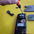 Making a wireless doorbell with your own hands Making a doorbell from an old mobile phone
 Schottky diodes reference book imported markings