The connections in the junction box are twist-free. Wire connections in the junction box. Why use a junction box
One of the stages of electrical installation work is the connection of wires in junction boxes, which follows immediately after laying the cables. According to the Electrical Installation Rules (ELR), electrical connections of wires must be made only in junction boxes.
Today, there are many ways to connect wires in a junction box. The choice of connection type depends on the following factors: core material - copper, steel or aluminum; working conditions - on the street or in an apartment; number of conductors - two, three, four; the cross-section of the cores is the same or different. Based on these factors, the most suitable and correct method is selected.
Why do you need a junction box?
Quite often there is some neglect of the distribution box (junction box). Some people think that using it when laying wires is a waste of time. After all, it still needs to be fixed to the surface, and this is additional effort. It is much easier, for example, to twist the conductors, insulate the junction and “roll up” everything with plaster.
- But this overlooks some issues:
- During operation, free access to the wire connections must be provided. For example, if there is no light in some room or the socket does not work? The test showed that the reason was the lack of voltage. How to find a distribution box in an apartment or a faulty section of the circuit? Tearing off wallpaper, breaking plaster to gain access to twisted wires?
- If in the future you need, for example, to install an additional one (two, three). Connect them “in parallel” from the first? Is this always convenient? While connecting new wires in the distribution box will not be difficult;
- Proper connection of wires is using terminal connectors. How deep do you need to drill a “channel” in the wall in order to hide the terminal block there?
- In terms of fire safety, the advantage of such a box is undeniable.
Wire connection methods
Special Electrical Installation Rules (PEU) regulate the correct connection of electrical conductors by welding, soldering, crimping or using screw and bolt clamps.
The rules do not stipulate the most common connection method - twisting. Although a properly performed twist is more reliable than a poor solder connection.
- The choice of connection method depends on several factors:
- materials to be joined. It can be aluminum, copper or a combination of both;
- number of cores in the connection. You can connect not only two, but also three, four or more wires;
- cross-section and number of cores.
Twisting wires
To make such a connection, you need to strip the ends of the wires, carefully twist them with pliers and insulate the twisted area. Very simple and without material costs. But such a connection weakens over time due to residual elastic deformation of the material, which means that the resistance in the connection increases and the contact begins to heat up to the point of destruction and fire.

Therefore, in no case should you lay twisted wiring on flammable substrates, for example, in a wooden house. And one more prohibition - poor protection against moisture does not allow such a connection to be made in rooms with high humidity. In this way, it is strictly forbidden to connect dissimilar materials, multi-core cables with single-core cables and at a current of more than 3 A.
In order for the twist to be of high quality, you need to remove up to 80 mm of insulation from the wires, fold them perpendicular to each other if there are two of them, and parallel if there are three or more, and twist them tightly. The remaining ends of the wires must be removed with pliers in a screw motion, as if smearing the material of the wires into one another.
The total length of the finished twist should be at least ten, and preferably fifteen, diameters of the cores. If special caps or heat-shrinkable tube (cambric) are used for insulation, they are put on the wire before twisting.
It is recommended to put on the heat shrink tube twice, and lay the insulating tape in at least three layers. Whatever insulating material is chosen, it must also capture the wires’ own insulation to protect it from moisture and slippage.
Soldering wires

This method is the best in terms of its combination of manufacturability and reliability, but requires some skills to make a quality connection. Before soldering, the wires must be thoroughly cleaned of insulation and oxides, tinned if necessary and twisted not as tightly as with simple twisting, coated with flux and soldered.
By soldering you can connect both copper and, with some skill, aluminum wires, with suitable flux and solder. Do not use active acid flux, as it will destroy the connection by remaining on the exposed wires. The connection point is isolated in the usual way. The distribution box in this case is called a junction box
- Despite the undeniable advantages, this method also has quite significant disadvantages:
- the need for skills in work, the complexity of the process;
- use of a special tool;
- permanent connection, that is, for repair it must be completely removed;
- an increase in resistance in the connection over time, which deteriorates electrical conductivity and increases voltage losses in the network.
Welding wires
Welding is an even more reliable connection method than soldering, but it requires a welding machine with personal protective equipment and welding skills, which is much less common in everyday life. Unless you need to carry out electrical installation work in a country house yourself, then purchasing an inverter-type welding machine will be economically justified.

Welding inverters are small-sized, have a wide range of welding current control, and provide stable arc burning with low power consumption. To weld copper wires, carbon-copper electrodes or carbon rods from ordinary AA batteries are used.
Preparation for welding differs only in the density of the twist and the fact that the free ends of the two wires, even if there are more of them in the connection, are straightened and pressed parallel to each other to facilitate the formation of a melt ball. Then the twist is placed in a welding clamp (regular old pliers) and the ends of the wire are welded with a carbon electrode to the main twist for two to three seconds so that the insulation does not melt. After cooling, the welding site is isolated in the usual way.
There is often a temptation not to wait for natural cooling, but to use cold water to speed up the wiring installation process. But cold water causes microcracks to appear in the material, which naturally affects the quality of the connection.
Wire crimping

This method of connecting electrical wires uses special tubular sleeves or lugs. The industry produces sleeves for wires with a cross-section from 2.5 to 240 mm², and it is very important to choose the right one for electrical wires specifically for each connection.
To perform the work you need a special tool. This may be a crimping press or tongs, mechanical, electrical or hydraulic. Having selected a suitable sleeve and adjusted the tool, remove the insulation from the wires, strip the ends and apply quartz-vaseline paste to them, put on the connector and crimp.
If the tool is simple, then you need to perform several compressions at some distance from each other. Using a good tool, you can crimp the sleeve in one go. At the end, the usual insulation of the joint is performed.
The wires to be connected can be inserted into the connector from opposite sides so that their joint is approximately in the middle of the sleeve. It can be convenient to insert both wires on one side, and the total cross-sectional area of all wires should be less than the cross-section of the sleeve. High-quality installation and reliable insulation are the positive aspects of using crimping.
- But there are also negative points:
- the sleeve is deformed during crimping and its reuse is impossible;
- the need for a special tool for crimping the sleeve, adjusting it to length and removing insulation from the conductor;
- to crimp the connection of copper and aluminum wires, you need a rather rare special sleeve;
- Quite a lot of time is spent on installing electrical wiring.
Using clips (PPE)
The clamp is a cap with a square steel wire coiled into a spiral cone. For aluminum wires, the cone is filled with a special paste that prevents oxidation of the exposed ends. Information on the packaging with clamps will allow you to choose the correct size of personal protective equipment in accordance with the cross-sectional area and the number of connected conductors.
To connect the wires, their ends are stripped to a distance slightly less than the depth of the cap, folded together, slightly twisted, and the cap is screwed on top. There is no need to clean bare wires from oxides, since this work is performed by the edges of the spring, and its turns tightly press the cable cores to each other.
The use of such connectors is technologically advanced; they not only connect wires, but also insulate the junction, although they do not provide the same contact area as when twisted and soldered. The bright colors of the caps help during installation to mark zero, phase and grounding if the wires do not have.
- The disadvantages include:
- gradual weakening of the spring over time, and, consequently, an increase in contact resistance and voltage losses in the network;
- restrictions on the number of connected wires, you can connect two with a cross-section of 4 mm² or four with a cross-sectional area of 1.5 mm²;
- impossibility of mixed connections.

Connection using a bolt is a simple, reliable and effective method. You just need to have a short bolt of small cross-section, three washers and a nut. True, such a connection takes a lot of electrical tape, and it is not used in the distribution box due to its bulkiness. Put a washer on the bolt, then screw on the stripped wire, another washer (if connecting copper and aluminum), a second wire, a washer and tighten the nut tightly.
Screw terminals
Screw terminals allow for quick and neat installation. They are widely used when connecting lamps, switches, and sockets to wires. With their help it is possible, and there is no need to isolate the connections.
- The disadvantages of screw clamps include:
- the need for crimping or soldering a multi-core cable before installation;
- the need for periodic maintenance of connections, since the screws need to be tightened, that is, access to them is required.
Walnut clamp
This connector is named for its shape. It is a cable clamp with special plates with grooves for wires and four screws in the corners. The wires are stripped, inserted under the plate and secured with screws. Then the carbolite shell is put on.
With this clamp you can connect copper and aluminum, the insulation is quite reliable, the installation process is simple and does not cause difficulties. Basically, this outlet connection is used to drain apartments from a common aluminum riser. But besides tightening the threaded connections, there is another drawback - the dimensions, due to which the “nut” does not fit into the junction box.

Connection using terminal blocks is used in distribution boxes, when installing lamps, sockets and switches. The terminal blocks are small in size and easily fit into a box. A brass bushing is inserted into a small plastic case, into which screws are screwed on both sides.
Stripped conductors are inserted from the ends of the block and clamped with screws with force. For wires of different sections, terminal blocks with different inlet holes are designed.
- The quality of such a connection is high, installation is easy, dissimilar materials can be connected, but there are also significant disadvantages of terminal blocks:
- connecting only two wires;
- poor quality of the pads themselves, which can cause disruptions in the network;
- Care is needed when installing aluminum and stranded wires so as not to damage the contact due to the fragility of the metal.
WAGO connection terminals

This relatively new type of connection using insulated spring clamps (connectors) is the most reliable and safe today. Disputes regarding the reliability of connections using Wago terminals may be associated either with counterfeits on the market or with the wrong choice of terminal for a specific load.
International certificates and approvals protect the reputation of these products. Their only drawback is their high cost. A special screwless spring mechanism makes installation of connections simple and quick. for connecting wires can be reusable with a special lever that clamps the wire and releases it if necessary.
How to use Wago terminal blocks? Disposable terminals fix the core with some effort, but, according to manufacturers, it is impossible to release it. For installation, you only need to strip the ends of the wires and insert them into the clamp.- Advantages of WAGO terminals:
- possibility of mounting dissimilar metals;
- possibility of fixing more than two wires at the same time;
- neat fixation of thin wires;
- good connection quality;
- compact sizes.
Detailed connection diagram
During operation of the electrical wiring, malfunctions may occur - for example, a circuit break has occurred. If, during electrical installation, workers did without switchboards. boxes, and the joints were simply rolled up with a finishing material such as plaster, then in order to get to the joints again, you will have to disturb the external finish - tear off the wallpaper, break the layer of plaster, etc.
It is unlikely that anyone will be satisfied with such prospects. If in the future you need to install additional sockets, then in such cases it is not always convenient to pull wires from previously installed sockets; it is easier to organize the connection directly to the box.
If the wires are connected using terminal blocks, then you will have to drill a fairly deep channel into the wall, which is much more labor-intensive than a simple connection in a junction box.
Finally, from a fire safety point of view, the advantage of using junction boxes is undeniable. For the correct organization of electrical installation work, there are special Rules for the Construction of Electrical Installations (PUE), which also regulate the procedure for connecting electrical wires.
One of the very important steps when installing electrical wiring is connecting the wires in the junction boxes. It is very important to make the connection in the junction box reliable, because subsequently, access to it may prove difficult, especially since in some modern houses the branch boxes are completely plastered over.
There are several different ways to connect wires: regular twisting with a layer of electrical tape (or heat shrink), twisting with welding of the ends, twisting with PPE (tip with a spring), connection using Wago clamps.
Which of these methods is better has been debated for a long time. Many cite various documents and regulations that state that connections must be made by welding. However, this rule is valid for aluminum wires, which are now practically not used anywhere. For copper, the reliability of welding is somewhat questionable, although it is still better than conventional twisting with electrical tape.
If you still decide to connect the wires by twisting them with electrical tape, then it is better to use heat-shrinkable tubing and wrap it with a small layer of electrical tape. The most optimal, in my opinion, is the connection using PPE (connecting insulating clamp) or Wago.
What we see after plastering the walls:

We take out the cables and clean the box. We cut the cables with a margin and make them the same length. I do about 70-90 mm, if measured from the wall.

Remove the insulation from the cable.

We clean the wires. The length of the bare copper section is about 30-40 mm

Then we twist it. It is convenient to do this with pliers. We bite off the ends a little.


We wrap a layer of electrical tape over the PPE, I use black fabric electrical tape.

Then we carefully stuff everything into the box. After puttying, the box will need to be closed with a lid.

Below are photos of the connection using Wago clamps.

We expose the wires; the length of the exposed copper section should be about 8-10mm.

We insert the wires into the clamps and snap them into place. Make sure that the clamp holds the conductors well.

Then, carefully put everything into the box.

Connection creation mechanism
Wiring your home is not difficult. To do this you need to have the necessary knowledge and equipment. The equipment is purchased in the store; you don’t even need to buy knowledge. At the very beginning, a diagram of the electrical network should be drawn up. In most cases, the owner of the construction hires an electrician who does not imagine the future location of the furniture and, as a result, switches are covered by doors, sockets in the corners are covered by furniture.
- As a rule, electricians draw diagrams with chalk on the wall of the future equipment, but it is better to place a diagram of the electrical network with the placement of electrical current collectors on the floor plan as a separate drawing, including the switching (connection) of the power cable cores in the distribution box - this will help:
- calculate the load on the electrical network;
- wire cross-section;
- divide consumers into groups.
- In terms of a household electrical circuit, there are at least two groups of electrical consumers:
- lighting;
- power part, that is, sockets.
It is best that these two circuits are mounted with separate power cables. If you plan to install powerful electrical appliances: electric stove, oven, boiler - these devices must have their own separate circuit, i.e. separate switch, fuse and cables.
Connection of wires in the junction box according to the PUE
PUE is a collection of regulatory documentation for the design and installation of electrical circuits; in fact, it is a desktop Bible for all people who begin to engage in electrical work. The collection shows the basic principles of creating circuits, the rules for their calculation, protection and communication devices. Further, all descriptions of electrical devices will be in accordance with the rules according to the PUE.
Selecting the cross-section and brand of wire
To lay electrical wiring in rooms and connect wires in a junction box, according to the PUE, the conductors must have a different color insulating coating, from the same manufacturer with the same color scheme. For wiring, it is best to use VVGNG brand wire - single-core copper, flat, double insulated, best with the additional designation NG, which means non-flammable.
It is best to purchase a cable from a well-known manufacturer, which must have a certificate. There is no need to take a wire without markings; electrical wiring in the house is, first of all, safety and is done for more than one year, so saving is inappropriate here. It must be taken into account that a copper cable with the same cross-section can withstand one and a half times more load than aluminum.
Attention! For a capital circuit, you cannot use a multi-core PVS or ShVVP cable. Although these wires are soft and more convenient to lay, they have a higher current resistance, and accordingly they will heat up more when a load is connected.
Power calculation
One of the basic rules for calculating a cable: 1 sq. mm is used in the calculation - 9 A. of electric current, that is, a cable with a cross-section of 1 mm can withstand the load of a kettle or iron with a power of 2 kW.
- Based on these recommendations, at least the following should be used for wiring in the house:
- lighting core is 1.5mm square, which corresponds to 10 - 12A;
- sockets in rooms are 16A, which corresponds to a cross-section of 2.5 mm. sq.
- kitchen electric ovens, the wire for which must withstand 25A. - this is a 4mm section. kv;
- The core of a four-burner electric stove must withstand 32A. - cross section 6 mm2.
Correct choice of electrical connection. wires in the junction box depends on its cross-section.
Attention! You cannot use electrical cables from different manufacturers, as they have different specific (ohmic) resistance per 1 linear meter.
Electrical junction box and wire connection
After laying the wires, according to the drawn up diagram, they must be connected to each other. In order for the connection to be in one place, there are communication boxes (distribution boxes). Depending on the installation, device connections can be round or square, deep or shallow, and are divided into internal (for hidden wiring) and external according to the method of fastening.
According to the requirements of the PUE, the electrical cable must extend at least 15 cm from the ceiling, taking into account all canopies. At the same distance, a device for switching cable cores is also attached. To install the internal box, a niche corresponding to the outer diameter of the sleeve is drilled in the wall; for external mounting, it is made directly to the wall.
How many wires can you twist in a junction box? You should not skimp on junction boxes and try to put as many wires there as possible - it will be inconvenient to connect, and all of them may not fit. As a rule, 3-4 wires are inserted into one junction box.Basic wiring diagrams
When making connections in a junction box, knowing how to connect the wires is not everything. You need to figure out which wires to connect.
How to connect sockets
How to wire a socket from a distribution box? As a rule, the socket group runs on a separate line. In this case, everything is clear: you have three cables in the box, each with three (or two) conductors. In this case, usually brown is the phase wire, blue is neutral (neutral), and yellow-green is ground.In another standard, the colors may be red, black and blue. In this case, the phase is red, blue is neutral, green is ground. In any case, the wires are collected by color: all of the same color in one group.

How to disconnect a junction box. The wires brought into the junction box are folded, stretched, and cut so that they are the same length. Do not cut short, leave a margin of at least 10 cm so that if necessary you can re-seal the connection. Then the conductors are connected using the chosen method.
If only two wires are used (in old houses there is no grounding), everything is exactly the same, only there are two connections: phase and neutral. By the way, if they are the same color, first find the phase (with a probe or multimeter) and mark it, at least by wrapping a piece of electrical tape around the insulation.
If there is a switch, the matter is more complicated. There are also three groups, but their connection is different.
- Eat:
- input - from another junction box or from a panel;
- from the chandelier;
- from the switch.

How should the circuit work? Power - “phase” - goes to the switch key. From its output it is fed to the chandelier. In this case, the chandelier will light only when the switch contacts are closed (the “on” position). This type of connection is shown in the photo below.
Connecting a single-key switch in a distribution box
If you look carefully, this is what happens: the phase with a light wire goes to the switch. It leaves from another contact, but this time blue (do not mix it up) and connects to the phase wire that goes to the chandelier. Neutral (blue) and ground (if network) are twisted directly.
Testing wire connections in junction boxes
After all connections have been made, the exposed sections of the conductors are insulated using heat-shrinkable tubing, and the wires are laid in junction boxes. The boxes themselves are left open until the installed electrical wiring is tested. First, voltage is supplied to the connected lines by turning on the corresponding circuit breakers.
If, after switching on, nothing sparked anywhere and the machine was not knocked out due to a short circuit due to an erroneous connection of wires or poor-quality insulation of connections, the electrical wiring is tested with load current (loading), which is carried out by connecting various electrical appliances to the mounted lines. It is recommended to load each line with the maximum permissible current.
The download should continue for some time (preferably several hours). During this period, possible electrical installation defects will have time to manifest themselves. A visual inspection of the connections in the junction boxes should be carried out - signs of high temperature will be visible by melting of the insulation or terminal blocks. It is also important that there is no characteristic odor of overheated or burnt insulation.
After relieving the voltage, you should check all connections by touch - they should not be hot. If, when loading electrical cables with the maximum rated current for several hours, no comments are identified regarding the operation of the connections, then the electrical installation is considered normal, the junction boxes can be closed and the wiring can be put into operation.
No electrical wiring diagram can do without some kind of connections, branching wires or cables. There is a special box for this purpose. It is located under the ceiling and is a round or square box made of polymer material.
In this material we will tell you how to make connections correctly, demonstrate diagrams, photos and video instructions.
Why use a junction box
There are cases when, when installing electrical wiring, they neglect the installation of such distributors, considering that this is just a waste of time, since the box must first be installed, then the connections to it must be made, which will lead to additional difficulties. It’s easier to simply twist, insulate and simply plaster the wall. But here you need to think a little ahead, since in this case important points are missed:
- No free access to wires. For example, if the socket in your room does not work or the light has gone out, and after checking it turns out that the problem is a lack of voltage. How to check? Completely remove the trim? Tearing off wallpaper and plaster to get to the twist? This will ruin your renovation.
- If you want to install an additional outlet. It is not always convenient to connect it by laying wires from a previously installed outlet. Thanks to the distribution box, you can easily make new connections.
- The regulatory document PUE states that “places of connections and branches must be accessible for inspection and repair,” therefore the installation of such a distributor cannot be neglected.
- The absence of such distributors is contrary to fire safety standards.
As you can see, the distribution box plays an important role. But installing it is just the beginning. All that remains is to connect all the wires in it. What's the best way to do this? Let's look at some ways.
Types of connections

What is the task when connecting wires? Ensure good contact between the cores so that the chain does not break and there is no risk of a short circuit. In order to ensure this, you can act in several ways:
- Twisting.
- Crimping.
- Welding.
- Soldering with a soldering iron.
- Use of screw terminals.
- Bolted connections.
These are time-tested methods that you can use to ensure reliable contact. Let's take a closer look at each of them. You will learn how to properly connect wires using any of these options.
Twist

Such twists in the junction box are officially prohibited. The seventh edition of the regulatory document PUE, chapter 2, paragraph 2.1/21 lists all types of permissible connections, but there is no twisting in them. And this is not surprising, since such a contact is sensitive to pulse current and has a high transition resistance. Over time, the contact will deteriorate and simply burn out. Due to the fact that the contact area is small, heating occurs under heavy loads and the contact is weakened even more.
This option is chosen because of its simplicity. It is enough just to strip 10–20 mm of insulation and twist the wires together using pliers. This is what our fathers and great-grandfathers did. But such a connection is often unreliable, especially if an aluminum core is used.
Crimping with a connecting sleeve

A fairly reliable method that will require the purchase of a connecting sleeve. You need to select it based on the diameter of the bundle being connected. Depending on the wires you connect, the material of the sleeve itself is selected. For copper wires the sleeve must be copper, for aluminum wires - aluminum. To ensure a reliable connection, the sleeve is crimped with a special tool called press pliers. This technology is quite effective and is included, along with other methods, in regulatory documents.

To connect this way you need:
- Remove the insulation, taking into account the length of your sleeve.
- Twist the wires into a bundle and insert them into the sleeve.
- Compress the sleeve using press pliers.
- Insulate the twisting area with heat shrink or insulating tape.
It is not recommended to use pliers in such work, since the connection will not be reliable enough. It is much better to buy press pliers or borrow them from good neighbors.
Welding

This method can be called the most reliable and safe, because the wires are connected using fusion and become one. Due to the fact that the welding will not oxidize, such contact will not weaken over time. But to carry out such work you will need skills in working with welding equipment.
In addition to skills, you must prepare:
- 24 volt welding machine with a power of more than 1 kW;
- welding gloves for skin protection;
- welding glasses or mask;
- sandpaper for stripping wires;
- stationery knife for removing insulation;
- carbon electrode;
- flux, thanks to which the melt will be protected from exposure to air.

After all the tools and materials are ready, all that remains is to do the welding, which will not be difficult. The work can be divided into several steps:
- Remove 60–80 mm of insulation and clean them using sandpaper. The veins should shine.
- Connect the wires using the twisting method, twisting one onto the other so that the ends are level with each other. It is recommended to make the length at least 50 mm.
- Pour flux into the recess of your electrode.
- Place the ground of the device on the bare wire, turn on the welding machine and press the electrode to the top of the twist.
- Hold the electrode until a ball called a contact point forms. This usually takes 1–3 seconds.
- All that remains is to clear the point of flux and insulate the welding site with heat-shrinkable tubing or electrical tape.
This type of connection will last a long time. In some old Khrushchev buildings, such welding lasted 50 years and consistently performed its function.
Soldering with a soldering iron

The method is very similar to welding, only in this case the wires are connected using solder. For these works you will need a soldering iron. To work you will need:
- soldering iron;
- fine sandpaper;
- rosin (flux);
- brush for applying rosin;
- tin-lead solder.
The operating procedure is the same as for welding:
- Removing insulation and cleaning with sandpaper.
- Twisting.
- Application of flux.
- Direct soldering. The soldering iron melts the solder, which should flow into the twist itself, reliably connecting the wires to each other.

Often copper wires are soldered using this method, but if you purchase special solder for soldering aluminum, you can also solder copper from aluminum.
Using screw terminals

This method is fast, simple and effective. And most importantly, such clamps can combine dissimilar metals. For example, if you need to connect aluminum and copper conductors, which in itself, as you know, is contraindicated. These clamps are very simple and compact, and their cost may pleasantly surprise you.

To connect wires with clamps you only need to complete 2 steps:
- Remove 5 mm of insulation.
- Insert into the clamps and tighten the screw.

That's all, as you can see, everything is very simple and fast. It is only important to control the force with which you clamp. If you tighten the screw too tightly, you may damage the wires. You need to be especially careful when working with aluminum wires.

The only disadvantage of a screw connection is that when working with a multi-core cable, it must be crimped with a special nozzle to ensure normal contact and integrity of the wire.
Bolted connections

This connection is quite reliable, but cumbersome. It is not suitable for modern distribution boxes due to its dimensions, but for large old-style boxes it is just right. This method can be used to connect both homogeneous and dissimilar metals. The work is carried out as follows:
- A steel washer is placed on the bolt.
- The insulation is removed from the conductors and they are formed into a ring.
- The first ring is put on the bolt.
- Then comes another steel washer, which is placed on the bolt after the first.
- The second connecting wire is put on top.
- This entire “sandwich” is clamped with a nut.
- In the end, everything needs to be insulated.
It is this design that makes the contact bulky. If you need to connect several pairs of wires, then this option will not be the best.

This method can be called the most modern, popular and easy to use. All you need is to buy special terminals at the store. Inside these terminals there is a special paste that prevents metals from oxidizing. Thanks to this, various metals can be inserted into such joints.
The work is as follows:
- 10 mm of insulation is removed from each wire.
- The lever, which is located on the clip, rises up.
- The conductors are inserted into the connector.
- The lever lowers to its original position.
If your clamps do not have levers, they must be inserted until the terminal snaps into place.

We have looked at the most reliable methods by which you can combine wires in a junction box. This is a very important stage of electrical installation work, since 70% of errors during the work consist precisely in incorrect connection of conductors. But if you, even without experience in such work, use the methods given in this article, you can easily do everything in accordance with the requirements of the regulations. But which of these methods to choose depends on your capabilities and desires.
Video
This video shows how to connect wires in a junction box:
You will learn everything about sleeving wires or crimping lugs from the material provided in this video:
Scheme


When repairing electrical wiring yourself, you should pay special attention to the connection of wires in junction boxes, because electrical engineering, as electricians say, is the science of contacts, both desirable ones, ensuring an uninterrupted supply of electricity, and unacceptable ones, due to which many accidents occur.
This article, with the help of links to other materials of this resource, will present all the minimum knowledge and skills required by a home handyman for successful electrical installation, and will also describe step by step the entire process of connecting wires in a junction box, starting from the preparatory stages, ending with the introduction of an installed home network into operation.
The scheme is the most important stage
For an experienced electrician, it will not be difficult to connect a switch and a light bulb without a drawing, making a connection of wires in a junction box, guided by the color marking of the cable cores or by the results of testing already installed wiring.
But experienced craftsmen succeed in such work only because connection diagram clearly imprinted in the mind thanks to many years of practice.
 A simple diagram of wire connections in a junction box when connecting a switch and a light bulb
 If a master needs to carry out electrical wiring at any facility, then he will begin first by designing a circuit, if other specialists have not done this before him. Of course, there are standards, GOST and SNiP, according to which all electrical wiring drawings are made, but for an apartment or private house, a hand-drawn diagram is suitable, the main thing is that it subsequently works properly and safely.
This approach not only protects against errors, but also allows you to save time by dividing labor - when carrying out electrical installation in a junction box, the electrician will not be distracted by drawing up a wiring plan, while simultaneously trying to keep the planned lines and connections in his head.
 A more complex connection diagram for a two-key switch
 Examples of schemes for and apartments can be viewed by following the links. You will also need to familiarize yourself with the graphic symbols of the network elements so that you can consult with a familiar mechanic by showing him the diagram, or in the future carry out electrical wiring repairs by checking the saved drawing.
The importance of planning electrical wiring is also determined by rationality and efficiency. When drawing up a wiring diagram, you need to draw up a plan in such a way that there are as few junction boxes in the apartment as possible, because each connection of wires increases the risk of losing contact.
 Example of a hand-drawn wiring diagram (blue circles indicate junction boxes)
 When connecting one socket or switch, many electricians advise doing without a distribution box altogether and connecting the wires in the socket box. This decision is determined by the reluctance of apartment owners to provide access to the distribution box, as required by the PUE (in their opinion, the interior of the home is deteriorating). The socket or switch can be easily disassembled, which provides access to the connection of wires in the socket box.
Quote from PUEA detailed story about the various wiring diagrams in junction boxes is shown in the video:
Correct pin markings
In order to connect the wires in the junction box according to the diagram without undue doubt, it is necessary that the terminals of the laid electrical wiring be marked. Very often, disconnection (dividing the main electrical wiring line into several branches) is made when all the wires have already been laid and hidden under the plaster, and there will be no way to visually trace the purpose of the cables.
 It's easy to get confused without being sure of the purpose of the same cables
 In order not to waste time on cables, which is also described on this site, you need to mark their ends at the stage of laying the cables. In some cases, if there are few wires in the distribution box, you can be guided by the color of the insulation of the current-carrying conductors. But with a large accumulation of cables, the colors of the wire insulation will be repeated, so the likelihood of error increases.
To eliminate the possibility of incorrect connection, you must label ending laid cables in any available way. The industry produces many different tags designed to mark terminals. Very often, electricians use transparent heat-shrinkable tubing by inserting a strip of paper with a terminal symbol inside.
 Samples of industrially produced cable marking tags
 You can also use transparent tape to wrap it around tags with inscriptions. As a last resort, use a marker or felt-tip pen to write the designations directly on the wire insulation or on the wall - but there is a risk that the inscriptions will be erased during the installation process.
 Electrical wiring terminals are marked on the wall
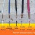
 You should also strictly adhere to the color marking of the cables (brown, red, black - phase, blue - working zero, green with yellow stripes - protective conductor PE).
 Generally accepted color coding for cable core insulation
 Installation of distribution box
Before starting electrical installation, you need to make sure that the junction box is securely fixed. , which depend on the type of wiring, are also described on this site. The importance of fixation is determined by the possibility of damage to already connected wires when manipulating the junction box and cables.
When working with single-core wires, frequent bending of the current-carrying wires should be avoided. Although stranded wires allow frequent bending, mechanical loads and the weight of a loose cable of hanging electrical wiring can damage the finished connection, so it is important not to violate electrical installation technology.
PUE requirement for fixing cables and boxesIf hidden wiring is installed in a brick or concrete wall, then the wires are laid in a groove made manually or using tools (grooving), and socket boxes and distribution boxes are mounted in holes that are drilled into the wall using a special crown. Fixation is carried out using plaster or alabaster.
 Box bit for drilling holes for distribution boxes
 Each type of wire connection requires a certain length of leads. For example, when using very bulky connecting blocks that have bolted connection terminals, craftsmen try to leave as little free length of wires as possible so that all connections fit into the box.
But, if welding of wires is used, then the length of the bare conductors should be about seven centimeters to prevent the insulation from melting during strong heating, plus the length of the insulated conductors for convenient and safe installation. Long exposed connected wires are insulated and laid in a junction box.
 Wire connections are made by welding
 The above examples mean that, regardless of the chosen method of connecting the wires, the length of the leads protruding from the junction box must be at least ten centimeters, because excess conductors can always be cut off, but it will be extremely difficult to extend them, and the reliability of the entire electrical wiring line will deteriorate. .
Conductor training
At this stage, the master must finally decide how to connect the wires in the junction box, and accordingly prepare guides– remove the insulation and bend the cable cores. A list of existing types of wire connections is given below, and now, regardless of the chosen method, special attention should be paid to the quality of stripping and preparation of conductors for electrical installation.
 Stripped wires are ready for connection in the junction box
 To carry out any electrical installation, the master must have, which you can familiarize yourself with by clicking on the link. At this stage, the wires are prepared for connection - stripping of insulation. Particular care should be taken in this process, since when using improvised means (knife, pliers, wire cutters), invisible damage to the current-carrying wires is possible.
 Professional electrician's tool kit
 As wires are bent and subsequently installed, subtle cracks in the metal can become larger, impairing electrical conductivity and possibly leading to breakage and loss of contact. At high currents, a large amount of heat will be released in the thinnest section of the circuit (at the crack site), which can heat the insulation and even the metal of the conductor itself to the melting point.
With a large current in a broken conductor, an avalanche-like process occurs - when heated, the resistance of the material increases, which further increases the heat release. This process ends with the melting of the conductor metal and the appearance of an electric arc, which, burning other wire connections in the junction box, renders them completely unusable.
 Photo of an electric arc burning in a junction box
 Without a doubt, a real master, even with the help of a kitchen knife, will be able to carefully and quickly remove the insulation without damaging the current-carrying conductor. But for people without experience it will be very difficult to avoid subtle damage to the material of the conductors, therefore, in order for the connection of wires in the junction box to be of high quality, it is necessary to use special ones (strippers).
 Variety of stripping tools
 Many people have seen the picture that some craftsmen remove insulation with the help of teeth. There is absolutely no need to follow this example, in which case purchasing a professional insulation stripping tool will cost less than the services of a dentist.
An overview of various stripping tools is shown in the video:
Wire connection methods
As already mentioned, for various methods of connecting wires to a junction box, there is its own electrical installation technology, which consists of the length of stripped conductors, their bending and the use of appropriate tools.
Since each of the possible methods has many specific nuances and requires the use of special tools and skills, the types of wire connections are presented below in the form of a list with links:
- Terminal blocks;
- PPE caps;
- Connecting sleeves;
- Welding of conductors.
 Wiring in a junction box using terminal blocks
 Each of the above methods has its own advantages and disadvantages, which you must familiarize yourself with by studying the materials and following the links provided. You should choose the type of connections for doing electrical installation yourself based on the availability of tools, skills, the ability to purchase materials and the expected quality of contacts.
Most reliable welding of wires is considered, but it requires a special welding machine and specific skills. Soldering conductors, which also has good performance, requires soldering iron skills. Wago terminal blocks are quite easy to install, reliable if the products are correctly selected according to the load, and allow the connection of multi-core wires without the use of special lugs, but you should be wary of counterfeits.
 Connections in the junction box are made using Wago terminal blocks
 The use of sleeves is reliable; when using special products, it is possible to connect copper and aluminum, but the connection itself requires special pliers and is non-separable, which does not give a chance for easy correction of electrical installation errors. PPE caps are reliable if the technology is followed and the diameter is selected correctly. Terminal blocks require bolted connections to be securely tightened.
 PPE caps in distribution box
 It should be remembered that according to the PUE, twisting of wires is not allowed in its pure form
 Twisting in its pure form is not included in the list of compounds allowed by the PUE
 Testing wire connections in junction boxes
After all connections have been made, the exposed areas of the conductors are insulated using heat-shrinkable tubing, and the wires are laid in junction boxes. The boxes themselves are left open until the installed electrical wiring is tested. First, voltage is supplied to the connected lines by turning on the corresponding circuit breakers.
 Insulating connections in the junction box using heat shrink tubing
 If, after switching on, nothing sparked anywhere and the machine was not knocked out due to a short circuit due to an erroneous connection of wires or poor-quality insulation of connections, carry out tests electrical wiring with load current (loading), which is carried out by connecting various electrical appliances to mounted lines. It is recommended to load each line with the maximum permissible current.
The download should continue for some time (preferably several hours). During this period, possible electrical installation defects will have time to manifest themselves. A visual inspection of the connections in the junction boxes should be carried out - signs of high temperature will be visible by melting of the insulation or terminal blocks. It is also important that there is no characteristic odor of overheated or burnt insulation.
 Melted insulation of one of the connections in the junction box
 After relieving the voltage, you should check all connections by touch - they should not be hot. If, when loading the electrical wiring with the maximum rated current for several hours, no comments are identified regarding the operation of the connections, then the electrical installation is considered normal, the junction boxes can be closed and the wiring can be put into operation.
One of the main difficulties that arise in the process of installing electrical wiring with your own hands is the need to connect the wires in the electrical distribution box. In order to prevent common mistakes and, as a result, malfunction of switches or sockets, we will consider each stage of independent work.
Almost every person, one way or another, has an idea of what a junction box looks like. But not everyone knows why it is actually needed and how it works. Let's look at the general data that we know about this element.
Distribution boxes vary depending on their shape, as well as the specific application. Some of them are rectangular in shape and some are round. This setting does not affect functionality in any way.

As for the features of application, there are:
- distribution boxes for hidden wiring;
- distribution boxes for open wiring.
They differ from each other in the method of fastening, some features of the device, and in some cases, in size. In any case, they have one single purpose - routing wires from the panel to separately located points of energy consumption, for example, switches, lamps, sockets. At the same time, the distribution of electricity must be uniform to avoid interruptions in the operation of devices.
To achieve this goal, electrical wiring is divided into separate lines or so-called groups. Separate wires are laid in each room, which will supply the devices with electricity, ensuring their operation. It is at this stage that distribution boxes appear. They are installed at nodal points where the wires are connected to each other.
It is necessary to buy a distribution box for electrical wiring, first of all, for fire safety reasons. Since it is at the places where the wires are connected that the risk of a fire is greatest. If contact is broken, the resistance increases and the connection begins to heat up. In some cases, this may cause a fire.

External electrical distribution boxes serve as an insulating layer between a potential fire source and surrounding objects. In addition, they also have a significant aesthetic role, hiding not always beautiful wire connections from view.
Is it possible to do without installation junction boxes?
Some argue that the presence of distribution boxes in the house is not at all necessary. But in fact, in order to do without them, it is necessary to lay a separate wire from the panel to each place where electricity is consumed. To do this, you will need to make many grooves in the wall that are deep and wide enough to lay wires in them in several rows. All this will entail additional costs of finance and effort.
If, when refusing to use junction boxes, you are guided by the fact that laying separate wires generally eliminates the presence of connections in the electrical wiring, and therefore is safer, then there is a good answer from experts. The connection of wires, carried out in accordance with all standards and the wiring diagram in the junction box, does not pose a danger. In any case, you can always turn to specialists for help.

Junction box: sizes and prices
Each installation junction box has a number of its own characteristics, among which size and price play a special role. Let's consider the three most popular options that are usually installed in residential buildings:
- Distribution box 100x100x50 mm IP54.
- Junction box IP65 88x88x53 mm.
The first option is one of the most accessible and at the same time widespread. For example, a Tyco distribution box can be purchased for only 50 rubles. Its low cost is due to domestic production, as well as minimal configuration (body and cover).
The second option also has a minimum cost - 46 rubles. It is made of propylene and LDPE. Of course, it cannot be said that it will ever be able to compete with metal junction boxes, but it more than fulfills its function of protecting wires from precipitation and wind.

The third option, made in Germany, will cost you a little more, about 211 rubles. At the same time, the characteristics and dimensions of the distribution box are not much different from the first two options. However, according to the manufacturer Hensel, the plastic used to make their products is of very high quality and meets all the requirements for electrical wiring elements.
Of course, these are all fairly simple and cheap options. Electrical distribution boxes with terminals will cost many times more. But even here we can say that their price is justified by the ease of connecting the wires and their further maintenance.
Helpful advice! If you don't want to skimp on safety, then you should consider purchasing an explosion-proof junction box.

Terminals occupy a special place in the arrangement of electrical wiring. Installation of a distribution box of this type is the easiest and does not require special skills. The bottom line is that the box is already equipped with special clamps that are designed to connect wires. Compared to conventional ones, such distribution boxes have a number of advantages:
- installation and dismantling of conductors is carried out much faster, and there is no need to use any additional tools;
- thanks to the use of a special paste, you can connect wires made of different materials, for example, copper and aluminum;
- a special wire placement system helps maintain order in the box, which reduces the risk of a short circuit to zero;
- The special design makes it easy to measure current without the need to remove insulating materials from the wires and does not affect the integrity of the system at all.

For open wiring, these types of junction boxes have become the most popular option. After all, the absence of the need to twist and connect the wires yourself made using the terminals very convenient. Today there are many different options on sale, including an explosion-proof terminal box.
Connecting wires in a junction box for electrical wiring in various ways
It is generally accepted that good contact is the result of correct connection of wires to each other. If the work was not done well enough, this will immediately become noticeable due to weak contact or its complete absence. In addition, problems can arise at the moment when you plug in some fairly powerful device.
All this, of course, causes a lot of discomfort. And it is much easier to take care of this in advance, at the stage of installing electrical wiring, than to try to solve this problem over time. Let's look at the most popular ways to connect wires to each other:
- twisting wires in the junction box;
- crimping;
- welding;
- commissure;
- use of contact screw clamps;
- bolted connections;
- self-clamps.

All these methods are quite simple to implement and do not require special skills. Let's look at each of them in more detail to get an idea of how best to connect the wires in the junction box.
How to properly connect wires in a junction box
In order to independently carry out all the work correctly, you should take into account only one main requirement that applies to the installation of distribution boxes: it is necessary to ensure free access to all wire connection points. This is necessary in case one of the sockets or switches malfunctions.
Note! If during initial installation the junction box is hidden behind the finishing coating, then at the first malfunction you will have to completely remove it in order to carry out repairs.

The problem may not always be hidden there, but it will never be superfluous to check the presence of contact. Therefore, think through everything in advance so that any repair work can be carried out as easily and quickly as possible. In this case, connecting the wires in the junction box can be done in any way convenient for you, which will be discussed below.
Connecting wires in a junction box by twisting and crimping
Almost everyone knows how to twist cleaned wire ends. However, if we are talking about connecting wires in a junction box, it is worth remembering the regulatory documents that cover this issue.
Twisting is considered an unreliable connection option, since the contact area is very small, and you cannot count on full contact between the wires. In addition, over time, even this small contact tends to weaken, which makes it impossible to use powerful devices that place a serious load on the system.
A much more reliable method is considered to be crimping, for which a special connecting sleeve is used. The main parameter for its selection is the thickness of all the wires that will be placed in it. The material of manufacture can be either copper or aluminum, and the choice depends on what material the wires themselves are made of.

In order to ensure fixation, a special tool is used to compress the sleeve. This can only be done with press tongs. It is strictly not recommended to use it for this purpose. Otherwise, this technology fully complies with all standards and requirements stipulated by regulatory documentation.
Here's how to connect the wires in this way:
- the insulation is stripped from the wires taking into account the required length, that is, the length of the sleeve used;
- the stripped ends of the wires are twisted and inserted into the sleeve;
- the sleeve is crimped using press pliers;
- using electrical tape or insulating the connection point.
How to connect wires in a junction box using welding
This method is considered to be very reliable, since the result is a single whole wire that is practically resistant to oxidation. By fusing the wires together, you get reliable contact that will not weaken over time. However, the implementation of this method is a little more complicated than the previous one, because you will need welding equipment and the ability to handle it.
List of tools that are necessary for wire welding work:
- a welding machine with a power of at least 1 kW and rated at 24 W;
- carbon electrode;
- rosin or flux, which will further protect the metal part of the wires from oxidation;
- personal protective equipment: glasses and gloves for welding.
If you have at least minimal skills in working with a welding machine, as well as all of the above components, further stages of work will not be particularly difficult for you. The insulation is removed from the wires, and their interior is cleaned with sandpaper until shiny.

After this, twist the wires in the traditional way and pour flux into the recess of the electrode. Press the wires against it and hold until you see a ball appear, the so-called contact point. After this, the process of connecting the wires can be considered complete. All that remains is to clean the joint from excess flux, varnish and insulate.
Connecting wires in a junction box using soldering
At first glance, this method is similar to the welding method, but it has a significant difference. Solder melted with a soldering iron is used to solder the wires together. This is an authorized method that ensures a reliable connection. Its only drawback is that it is not very reliable in places where the wires are subject to strong heat.
Note! If you do not know how to solder, then it is better not to use this method. The connection may turn out to be too fragile, and with the slightest mechanical load or tension, the wires may simply break at the point of soldering.
In order to solder the wires you will need:
- soldering iron;
- tin-lead solder;
- rosin or flux;
- if using flux, use a special brush for it;
- fine sandpaper.

For the most part, the process of connecting wires is the same as in the case of welding. But it’s not the metal itself that melts, but only the solder. In this case, you need to carefully ensure that the molten solder flows inside the twist for a more reliable fastening. For the most part, this method is used to work with copper wires, however, provided you have special solder, the same can be done with aluminum ones.
Use of screw terminals and bolted connections
Using screw terminals is a fairly common method that is used by many due to its simplicity and convenience. However, it also has its disadvantages, which are useful to know about before starting work.
Initially, screw clamps were used to connect different metals that should not touch each other. For example, it could be copper and aluminum, which, in the presence of moisture, begin to interact with each other. Over time, this method began to be used for connecting wires. And it was even fixed at the level of regulatory documentation.
Note! When using this method on aluminum wires, you need to be aware that they will require periodic crimping to ensure that the contact does not lose or weaken over time.
Bolted connections are also quite often used to connect wires, however, if we are talking about hiding them afterwards in a junction box, then this method can be considered inappropriate. It's all about the cumbersome connections.

In order to connect the wires in this way, you need to insert a steel washer between them. This happens in the following sequence: a washer is put on the bolt, then one of the wires is put on, and then another washer. This is followed by a second wire and a nut that tightens the system. Of course, all this also requires good insulation, so the connection volume is decent.
Helpful advice! This method has its advantages - it is well suited for joining different metals, since a special paste can be placed inside to prevent oxidation processes.
Installation of distribution box for electrical wiring
Having figured out the ways in which wires can be fastened together, let’s look at how to install the system itself using the example of an IP55 distribution box for outdoor installation 100x100x50 mm.
Most often, installation is carried out in a blank wall made of brick or concrete. This may cause some difficulties as you drill a niche for it, but the system will be securely fixed. If the box has round holes, then you can use special drill bits. For rectangular or square ones, use a grinder with a special diamond blade designed for working with concrete.
After the niche is ready, be sure to try on the junction box for it to make sure that everything is prepared correctly. The distribution box must be completely placed in the wall so that after installation its front surface is at the same level as the wall.
Some junction boxes have special plugs that are specifically designed to insert cables in these places. They must be carefully broken or cut out, while maintaining the integrity of the overall structure. The ends of the electrical wiring are inserted into them according to the diagram.

Once you are sure that all the wires have been inserted into the junction box, you can begin preparing the mortar to fix it. The fixation principle is very simple:
- a certain amount of solution is placed into the niche prepared for the junction box using a spatula;
- the box with the cables already installed is pressed inside as deeply as possible;
- excess solution protruding from the sides is removed;
- if there is such a need, the box can be held with your hand in the first few minutes to allow the solution to set a little.
Helpful advice! Instead of mortar, you can use alabaster. It dries much faster and at the same time can withstand the weight of the box just as well.
Both when working with the installation of a junction box for open wiring, and in the case when we are talking about a closed system, high-quality installation largely determines the life and quality of service of the electrical wiring. The main thing in working with electricity is to correctly assess your capabilities and, if necessary, seek help from professional electricians.
Electrical wiring in the room must be safe and convenient to use. If you strictly follow this rule, then each energy consumer (chandelier, TV, computer, refrigerator) must have its own protection device against short circuits or overheating of the wiring. You can run a separate cable from the personal circuit breaker for each outlet and switch. Two more criteria oppose this: rationality and economy.
What are distribution boxes for?
Rational wiring looks like this:
That is, the total energy consumption of the facility is evenly distributed among the circuit breakers. In addition, consumers should be divided into groups, for example:
- Living room and bedroom lighting
- Kitchen lighting
- Lighting for bathroom and hallway
- Socket group (in each room)
- Power socket group (for powerful consumers, such as an air conditioner or an electric oven)
But with such a scheme, there may be many connections on one wiring line. It is not safe to make overhead connections and hide them in the wall. At a minimum, this does not make it possible to disable a faulty branch while leaving the rest of the circuit operational.
For normal distribution of lines, there are distribution boxes.

They are an insulated container, inside which switching (permanent) of electrical wiring lines occurs. The connection of wires in a junction box can be done in various ways, the main thing is to ensure reliable insulation between phases and a contact that can withstand the load.
The wiring diagram in the junction box allows you to save money when purchasing electrical cables, as well as avoid uncontrolled interweaving of wires in the walls. The so-called radial wires diverge from the shield with protective circuit breakers. On each of them there are connecting nodes: those same distribution boxes.
Important: The wire cross-section may be the same or different. The main condition: the power of the main cable cannot be lower than the power of the final wiring to the consumer (socket, light fixture).
In addition, there are certain methods and rules for connecting wires in a junction box. Let's talk about this in more detail.
General rules for switching electrical cables in distribution boxes
Of course, all requirements for energy supply are set out in the PUE.

This is an electrician's reference book. Moreover, there are fines for violating the Electrical Installation Rules. However, in practice, all these strictures apply only to institutions and organizations. In private households, responsibility ends with the wire coming out of the meter (electricity meter). The rest is up to the homeowner. To prevent an incorrect connection from leading to a fire or electric shock, you must follow simple rules:

In addition, inexperienced electricians often make mistakes and break off wires when stripping the insulation. If the wire is inserted into the box under tension, reconnection will be impossible.
Methods for connecting conductors in a box
There is no single possible method. When choosing a way to connect wires in a junction box, an electrician weighs all factors: from the cost of materials to the expected load.
- Terminals. There is an opinion that this method is the most reliable, but this is a false statement. Most often, terminals are used on boxes with ready-made contact pads.

This connection of wires in the box allows you to disconnect one of the lines at any time (for example, for repairs) without causing damage to the entire power system. There are two ways to connect, directly to the block (by making a ring from a wire core), or using a terminal. With the ring everything is simple, you just need to ensure that the wire is laid in such a way that when tightening the threaded connection, the contact does not loosen.

But with terminals everything is more complicated. It is irrational to crimp a single-core wire: you can mechanically damage the conductor, and the core will break off at any moment. And when laid in a box, a single-core cable with terminals takes up a lot of space, and it is difficult to separate different phases at a sufficient distance.
An excellent result is obtained when crimping a multi-core soft cable; the contact terminal fits comfortably. But stationary installation of a multi-core cable is nonsense.
Bottom line: Terminal blocks in the distribution box are convenient, but it is better to make the connection directly to the conductor under the screw, without using crimp terminals.

There are modern boxes with quick-installation contact blocks. This solution is really convenient, but is designed for light load.

Thus, the use of contact blocks is justified only if it is necessary to periodically disconnect one of the lines. And even then, sooner or later the conductor will break off.
- For standard wiring in an apartment (or household), the classics are still more suitable:

Welding wires in a junction box has been used since time immemorial. Anyone who repaired their Khrushchev or Brezhnev cars probably noticed a drop of solidified melt at the end of the aluminum strands in the boxes.
Today, the use of aluminum wiring is prohibited by the PUE, and the welding connection method is still popular. The point is this: after carefully twisting the stripped wires, the contact of the welding machine is briefly applied to the end point.

Usually this is a compact device of low power. It is used by almost all professional electricians. Works on the principle of a spot welding spotter. It will not be possible to light an arc, but the metal at the point of application melts properly. The figure shows the simplest circuit that can be assembled at home.
The connection quality is more than sufficient. In addition to the total twist length (40–50 mm), the ball at the end forms a point with minimal resistance. An additional plus is that this twist will not unwind even when moving the wires inside the box.

If a welding machine is not available, we limit ourselves to ordinary twisting. Of course, we make the connection not with our fingers, but with the help of pliers. All ends of the conductor must be stripped (but not reduced in cross-section), the length of the bare part before twisting begins is at least 70 mm.
Twisting is done after the wires are finally secured in the box. If the cable moves, the connection may become weak. The result is sparking, overheating, and contact breakage. It will be good if there is no fire.
- As an option, after twisting, the wires are soldered in the junction box.
Important! There is a widespread opinion among amateurs: under load, the twist will heat up and the solder will melt. Firstly: a load capable of heating a conductor to the melting temperature of solder is unrealistic at home. Of course, provided that the circuit breakers are in working order. Secondly: heating during twisting occurs due to loose contact, and this can be solved by soldering.
The reliability is not much worse than with welding. In this case, there is no need to purchase (do it yourself) a welding machine, a fairly powerful soldering iron, or even a hair dryer.
Tip: Use the most powerful soldering tool possible. It is better to expose the contacts to high temperatures for a short time than to heat the contacts slowly and for a long time with a weak heater.
During heating, monitor the condition of the insulation. If it starts to melt, take a break until it cools completely. Immediately after soldering, do not move the wire; allow both the solder and the insulation to cool.
Use refractory solders; these alloys have higher strength characteristics.
- Crimping. From the point of view of electrical conductivity, the quality of contact is no better than that of conventional twisting. But the strength of the connection increases significantly. If it is not possible to weld or solder the twist, crimp it using a special sleeve.

You can get by with pliers, but a special tool is still more reliable. There are bushings for parallel splicing of wires, and there are for fixing twists. There is no fundamental difference. If there are two or three conductors, parallel crimping is suitable. For larger quantities - crimping after twisting.
In fact, the methods discussed above are a modernization of the good old twisting. You should not be skeptical about the issue. Due to poor contact in the junction box, many fires occurred and damage to household appliances was caused. Therefore, when repairing electrical wiring in your home, use technical means to improve contact in the twist to the maximum.
Modern methods of connecting wiring in a box
The so-called quick fix pads. These products are widely offered in online stores and building materials markets.

Indeed, such devices make installation quick and convenient. The appearance of the connection is also pleasant. Therefore, such “electric clips” are loved by electricians who perform custom work.
However, this method has serious drawbacks. Let's make a reservation right away: the manufacturer does not promise high connection power: the characteristics are on the case. For an LED lamp, connecting a computer or TV - just right. But a refrigerator, electric stove, boiler cannot be connected through such a distribution box.
The contact area in such “quick releases” is small; the pad is connected to the conductor tangentially. With a light load, the current does not heat the surface too much. And when a serious consumer is connected, sparking, heating, and burning out of the connection will begin.
Conclusion
With all the variety of ways to connect wires in a box, traditional twisting remains the most reliable. Welding or soldering significantly improves contact.
No serious equipment is required; all work can be completed with basic electrical engineering skills.
Video on the topic
 How to choose the right cable cross-section
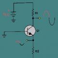 The simplest low-frequency amplifiers using transistors
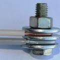 Calculation of cable cross-section by power