How to design a wooden airplane. How to build an airplane out of wood How to make an airplane out of wood
Every boy in childhood dreamed of being at the controls of an airplane. The sky, clouds, and travel have always attracted adventurers and brave men. But to feel closer to aviation, you don’t have to buy a plane ticket or enroll in a flight school. After reading this article, you will learn how to make an airplane out of wood with your own hands.
Required tools and materials
Before you search for a suitable aircraft model and its drawing, you need to provide yourself with the necessary materials. The best option would be. In its manufacture, three layers of birch veneer are glued together using phenolic glue.
In this case, the thickness of the material is important; it should be about 1 mm, but thicker sheets of plywood may be needed. If you don’t know how to make a flying airplane out of wood, then pay attention to this parameter. Moreover, this material is very light, flexible and durable.
When choosing plywood suitable for the job, you should pay attention to its appearance. Its thickness should be the same over the entire area. There must be no defects of any kind, delamination, chips or cracks. The material should be dry, so it is easier to process.
made of wood

Now that you have mastered the information on how to make an airplane out of wood in various ways, you can choose any of the options and modify it as you wish.
You can construct the structure yourself, but to do this you will need to study publications on the design of modern aircraft. Various virtual design programs may be useful.
If you are unable to find dry material, you can prepare plywood sheets yourself by keeping them in a room with low humidity and constant temperature for two to three weeks.
If you have never made and do not know exactly how to make an airplane out of wood, then take on the job only if you know what the future model will be like, or when its aerodynamic properties are not important (making a children's toy).
When making a decorative model or toy, you should get rid of sharp corners by chamfering.

If you are working on a model intended for flight, then special attention should be paid to the precise positioning of the tail and wings. After all, the aerodynamic properties depend on them.
Conclusion
Airplane models of varying levels of complexity are made by craftsmen all over the world. At the same time, the most complex controlled models can perform aerobatic maneuvers.
Having selected a suitable drawing, you can easily figure out how to make an airplane out of wood. However, such work will be uncomplicated only when making the simplest models. Novice builders will not be able to undertake more labor-intensive tasks; they should master the simplest technologies and schemes, as well as understand the process in more detail.
The plane can become a toy or a blank for further painting or decoupage. The wings and propeller are made from thin planks from vegetable crates, and the fuselage is made from 6 mm plywood. It would be better if everything was made of wood, but I was afraid that the openwork cabin would be too fragile
In profile. The wings and wheel struts are inserted into tight slots in the fuselage and could be held in place by a tight fit. But for strength, PVA wood glue was also used. Small smudges of glue are cut off after drying with a sharp knife. If they are serious, it is better to wash them immediately with a damp cloth, then the varnish in this case may be stained with glue residues.
-780.JPG)
All parts are carefully sanded before assembly. The collected ones are more difficult to skin.
-780.JPG)
The axles of the propeller and wheels are studs, although this is not the best choice. It was worth rounding the cap a little and sanding it. The screw and wheels are drilled to ensure free rotation. In the fuselage and landing gear there are holes for the axles of a smaller diameter so that the nails would hold tightly, but would not split the plywood into layers.
-780.JPG)
The propeller blades are cut at an angle, like fan blades. This can be seen in the last photo, a top view of the plane. So if you blow on it, the propeller will start to rotate and it seems that the airplane is about to take off!
Here I give my drawing for cutting out an airplane. 1 cell = 10mm
The screw is made from a plank 8mm thick, the rest can be made from plywood 4-6mm


Introduction
I was prompted to create my first plane by a simple lack of money and a desire to learn how to fly. Since the Chinese plane given to me by my girlfriend was repaired an endless number of times and, in the end, fell into a condition beyond repair, and there was not enough money to buy a new one, the decision was made to build my own. Moreover, on the modelworld.ru store forum, I was advised to do just that. Initially I tried to copy the fuselage of my Chinese aircraft, but building an aircraft requires at least some basic knowledge. Therefore, it is better to have at hand a manual already written by a more experienced designer. And, while still crawling on the Internet in search of a suitable aircraft, I came across the article “ParkFlyer 2 or our answer to Piper and Cessn” by Evgeniy Rybkin (link). A very good option for me: high-wing, which means easier and more predictable to control; I am also glad that the aircraft is domestic, since our aircraft are practically not represented in this class.
I read the article, and although there is a slightly different manufacturing method, I decided to build according to this manual. True, if we compare both options, then only the name of the aircraft will be common - after all, Evgeny Rybkin’s description is more suitable for those who already have experience in building models and have the necessary materials and tools. In some ways, my example looks like "building an airplane in unfavorable conditions." Therefore, the models differ in appearance (Yak-12 aircraft by Evgeniy Rybkin - on the left, My version of the Yak-12 aircraft - on the right):


The construction of my plane was carried out more intuitively than scientifically: no calculations were made, no engine was selected, but what was available was stuck in. The remoteness of the city in which I live has an effect - the only model store I know of is more than 100 km away, and in our construction stores it’s a real problem to buy a normal ceiling and good glue. Therefore, the construction process was constantly hampered by the lack of necessary materials and parts. As a result, something was taken from a crashed Chinese plane, something (and this is most of it) was invented from scrap material.
Since this is my first self-built aircraft, there were some mistakes. Therefore, in the process of creating the aircraft, it was necessary to look for different options for solving problems, and some corrections and upgrades appeared in the process. Therefore, it makes sense to read the article to the end so as not to repeat my mistakes.
I would like to add that this article should not be perceived as a guide to action or instructions for building an aircraft, as I, for example, perceived the article by E. Rybkin. It just describes the process of making a parkflyer by a beginner in the field of aircraft construction, practically from improvised means. But, if you are building your first plane, and you do not have the opportunity to get hold of branded parts, then, I hope, some points will be useful to you. In general, go for it, and everything will work out for you!
Materials and tools
In principle, I didn’t spend that much material on this plane. Considering that some components and parts were redone several times, trying to achieve a more accurate match, the amount of materials wasted is minimal. I spent the most time because due to work I could only work on the plane in the evenings.
The article by E. Rybkin describes the manufacture of an aircraft from PS-60 foam plastic. There, a special machine is used to cut it, where the role of a knife is played by a heated nichrome (maybe I’m wrong in the name) wire. Due to the lack of this device, I decided to make the model entirely from the ceiling. I didn’t have more accessible material at that time. I used ceilings from different manufacturers, different colors, but the same parameters: 500*500 mm, the same density, 3 mm thick, and it must look like a “Doshirak box.” It took me nine sheets for the plane. When buying a ceiling in a store, buy a bottle of ceiling tile adhesive. I used Master glue. As it turned out later, this is an analogue of the widely known Titan glue. In general, ask the seller, he will tell you.
Then we go to a stationery store and buy 30 cm and 50 cm wooden rulers there. I used 30 cm long rulers as ribs in the wing and for the rigidity of the fuselage. As practice has shown, for the rigidity of the fuselage it is better to use a 50 cm ruler - they are thicker. There, I bought colored tape to cover the model. Due to the limited assortment, I had to take white, blue and orange colors. I was looking for black tape to imitate glass, but couldn’t find it. But our stationery store sells knitting needles. I took four pieces of 2 mm and two of 3 mm. In principle, you can do without 3 mm spokes - I used them as a spacer between the wing and the fuselage, but the spokes are quite heavy, after several dashing turns they fell out, and I had to replace them with plastic tubes. If you do not have a ready-made motor frame, as in my case, then you will also need a sheet of plywood 3 mm thick and approximately 200 * 200 mm in size.
The tools I used: a utility knife with a replaceable blade, scissors, a gel pen, an awl and a 3mm Phillips screwdriver, a set of pins and, of course, rulers.
"Filling"
E. Rybkin’s article contains a lot of calculations. And, based on these calculations, the engine unit and other electronic components are selected. This is the right approach when creating a serious aircraft. Perhaps next time I build, I'll use this method. At the same time, I proceeded from what I had available. And I had the following: Futaba 6EXA equipment with a receiver, two Chinese motors, with rear and front mounting, a 30A regulator, two servos weighing 8 g and a force of 1.3 kg, hogs taken from a Chinese plane, two propellers measuring 10 * 7 and 8*4 with spinner and a Chinese battery with 8.4 volts and a capacity of 650mAh.
Drawing
I downloaded the drawings there, in E. Rybkin’s article and printed the sheets on a printer.

Gluing is very simple - there are marks on the sheets that you just need to align to get the correct ones, without shifting the lines. To transfer an image to the ceiling, you can use two methods. The first is to fix the sheet on the ceiling with pins and pierce it along the contour with a thin awl. Then, for clarity, you can connect the holes made on the ceiling with a pencil, or you can simply cut them with a sharp knife. On straight sections, it is enough to make several punctures, but on curves, the more often the punctures are, the more accurate the transfer will be. The second method is suitable if the drawing is printed on an inkjet printer. To transfer, lightly moisten the tile, attach the drawing and iron it on a flat surface with a warm iron. The image should remain on the foam. The main thing is not to overdo it with the temperature and not melt the ceiling.
When placing a drawing, it is worth remembering that ceiling tiles have different bending strengths. This can be easily checked by bending the sheet in different directions. This applies to the wing, since my halves of the left and right sides were placed diagonally, from one corner to the other. This made it possible to avoid gluing the fuselage from several ceiling sheets.
I would like to draw your attention to the fact that the top and bottom of the plane are given in halves, and they are of different sizes. To trace the lines correctly, you must first draw one half, and then make its mirror image. I divided the upper part into two sections - the front one goes from the nose of the car to the leading edge of the wing; rear from end to trailing edge.
The wing profiles, as well as the internal frames in the drawing, turned out to be smaller than we needed. Therefore, you will have to make them yourself.
Fuselage
After the bottom and sides of the fuselage are cut out, we mark on them where the frames will be located. To keep things simple, I transferred almost all the locations of the frames from the drawing.

With the exception of "A" and "B". I decided to use these two frames as a motor mount. Since I had two motors with different mounts, it was decided to make the motor mount universal for motors with front and rear mounts, reducing the distance between the frames so that both motors would fit. Subsequently, this arrangement was very useful - the initially installed motor turned out to be too weak.
The motorama was made from two 3mm thick plywood plates and two pieces of a ruler. Also, for strength and adjustment of the inclination of the plates, I added two corners at the base. In frame “B” or in the rear wall of the motor mount, do not forget to cut holes for the output of the motor wires to the regulator. The entire structure was glued together with epoxy resin. Initially I wanted to make a “crooked” frame, so that later I wouldn’t have to bother with slopes down and to the right. But on the forum of the website modelsworld.ru they dissuaded me in time and advised me to tilt the motor by placing washers under the base. Looking ahead, I will say that the structure turned out to be very durable - after several strong frontal impacts on the ground, the front wall burst at the place where the engine was mounted. The second option, when the frame itself is purchased, and the base is made of foam, I will not consider here, since this option has not yet been flight tested. And there is nothing complicated there: a foam base is made, reinforced with rulers for a ready-made motor mount.


You also need to think about where and how the “filling” will be located: servos, battery compartment, receiver and regulator.
For the regulator, I made a small podium from the same packaging foam, making a recess in it slightly thicker than the regulator itself, where I pasted two strips of double-sided tape. This was done for more comfortable work with wires when connecting and for greater safety of the regulator.
Immediately after the podium, on the bottom, I placed a power element for the chassis, again made from a ruler. The chassis will be screwed into it.
For the battery compartment, I used blocks of packing foam adjusted to the size of the battery and a ruler as frame “B” (before gluing, it is better to wrap the ruler with tape a couple of times, otherwise the battery will break if dropped). The compartment turned out to be universal - it can successfully accommodate both a Ni-Cd battery and a Li-Po battery. Moreover, there is enough space there to adjust the balancing by moving the battery. I also had a receiver there.
Immediately behind the battery compartment in front of frame "D" I placed the servo machine for the rudder and elevator. A styrofoam podium was also made for them, with niches cut out for cars. I glued strips from a ruler to the places where the fastening screws would be screwed.
Then I glued the frames “D” and “E”, having previously cut out grooves in them for reinforcing the sides of the fuselage. Also in the frame “D” a hole was cut for the rudder rods. In the photo above the hole is a circle, but I had to abandon that shape and make it square and cut off the top. That is, it turned out like an inverted letter “P”. This design turned out to be more practical.
When planning the plane, I thought of making the wings removable, inserted on spokes on the left and right sides, respectively. But, having already made this design, I realized its weaknesses. Firstly, we would have to think through access to the internal compartments. Secondly, in the event of an impact, most likely, the attachment points for the wings would simply be torn out of the fuselage. Therefore, I decided to make the wing fastening classic for such models - removable, with elastic bands.

In the picture, the glued rulers are what I did originally. The subsequent cutout for the wing is shown in red; blue - power elements from rulers; yellow - the approximate location of the holes for the sticks on which the elastic bands will be attached. The cut will depend on the shape of the wing. Of course, it is better to make such a cutout right away, when it is possible to attach both halves to each other, so that the result would be the same on both sides. In principle, I removed the upper part of the already glued and covered fuselage - it turned out not bad. But all the same, it is advisable to glue the bottom and sides after the wing has been made and the seats for it have been cut out in the sides.
Now, having already flown the finished model, I came to the conclusion that the rear power element is not necessary, since the frames and tape covering at the rear are quite enough. But if you are worried about strength, you can make it.
Since the bottom of the side does not have a straight shape, I did the gluing as follows: first I glued the central part, fixing the position of the bottom, side and frames with pins; after the glue had dried, I also glued the nose part; and finally glued the tail section. I glued the motor frame to the sides using epoxy resin.
After gluing, I got the following:

In the lower part, in front of frame “B”, on both sides I glued two plastic spare parts from the spokes onto epoxy, with the holes facing outwards. They come with knitting needles and are dressed at the ends. The wing struts will be inserted into these holes.
In the very corner of the back of the case, I placed a piece of foam. The rudder will be “stuck” into it. The upper part of the fuselage consists of two halves: bow and stern. After switching to the construction of an aircraft with wing fastenings on elastic bands, there was no longer a need to make the nose part with an approach to the wing. The photo shows with a dotted line where the cut should be made.

Before installing the rear upper section, it is necessary to place the steering gears and rods (bowdens) inside the fuselage. Since my rudder rod came out exactly through the rear fuselage cover, I had to make a small hole in it (the cover) for the bowden. I made another hole in the rear of the left side for the elevator rod.
The fuselage was covered with white tape. I didn’t encounter any difficulties here. But making the applications took some time.
To imitate the cabin windows, I made templates from cardboard. Then I simply placed them on blue tape, outlined them and cut them with a utility knife.
The blue stripe was made from a strip of tape. I applied the tape directly to the fuselage, marked it, ran a knife along the markings and removed the excess. But it was a big mistake to cut the blue stripe in place, on the fuselage. After hitting the ground, the ceiling burst exactly in the place where the cuts were, although when cutting, I tried to touch the foam as little as possible.


The inscriptions are printed on a printer, trimmed and pasted on transparent tape.
Elevators and rudder
There were no difficulties in making the steering wheels themselves. Problems arose during their installation - it was necessary to achieve an even installation so as not to experience problems during flights.
When making the elevator, it must be taken into account that the jumper connecting the two halves is quite small and requires reinforcement. I didn’t immediately pay attention to this, for which I was punished: in flight, this jumper broke, despite covering it with tape, and the RV acted like an aileron. The result is several barrels and land. You can strengthen it with a thin strip of ruler glued to glue, and also slightly increase the size of this area. There are also more practical options for amplification than I used. For example, carbon pipes. After strengthening, cover with tape. And one more important point: after covering, do not heat it! The adhesive tape already holds quite firmly, and if you start heating it, the stabilizer will most likely move, as happened in my case. I had to make a new one. The same applies to the rudder. The elevator was leveled using struts made from thin spokes. There were no problems when gluing it into the fuselage, so I see no point in describing it in detail.
But there were problems with the rudder - I didn’t want to install it straight. To glue it into the fuselage, I used rod ends glued to the spokes.
But this was not enough, and it was necessary to install supports from rulers. Later, I hid the supports, as well as the elevator reinforcements, under white tape so that they would not be conspicuous.

Wings
The most problematic part for me during production was the wing. I redid it several times, trying to achieve the same results on both wings. It turned out different all the time. Lack of experience affected.
An important point when placing the wing drawing on a sheet of ceiling tiles will be the choice of the direction of bending of the ceiling itself, as mentioned above. When marking the wing, we will need to make its mirror image with an indent slightly larger than the front height of the rib. That is, we outline one half, retreat the required distance (about 20 mm), turn the wing pattern over and outline the mirror image. In my case, the indentation was about 15 mm and, anyway, it was not enough.
A ruler was used as material for the ribs. Initially, I made an irregularly shaped rib with a sharp forehead, but then, after receiving advice on the forum, I corrected myself. In general, it is advisable to make a profile as in the drawing, but with dimensions suitable for our wing. There were four ribs on the wing: three on the wide part and one in the middle, between the end of the wide part and the end of the wing.


In the first three ribs, at the same distance, two holes were made for the spokes, which were originally intended as devices for attaching the wing to the fuselage. But even if you make a wing with a top mount, I think you can leave the spokes, as they will give the wing rigidity and prevent it from breaking.
When everything is prepared, we begin to bend the wing. On the Internet you can find many ways to bend ceilings. The essence is the same everywhere - you need to warm it up. I heated it with a heater. And the main thing here is not to rush. Choose a temperature at which it is not too hot, and the sheet bends as it should. Already on the next wings I did this: I took two wooden 50 cm rulers, applied them on both sides and bent (pressed) with the rulers, not with my hands. This was done so that there would be no dents from the fingers. Fixed it when gluing with clothespins and even paper clips. When gluing, when fixing, it is also better to use a flat backing in the form of rulers.


I only realized this when the wing, left to dry until the morning, had dents from clothespins and paper clips.
It so happened that on one wing, the end chord turned out to be 5-7 mm smaller than on the other. Having tortured several sheets of ceiling, I decided to make it simpler. I measured the missing piece, cut it out from scraps and glued it on. After covering with tape, the differences were not visible.


Next, we make the profile of the inner wing wall from a ruler. It is enough to simply attach the wing vertically to a sheet of paper and trace along the contour, and then transfer the resulting contour to a ruler. On this profile I had two rows of holes - the first for the spokes exiting the wing, and the second, slightly lower and slightly to the side for the spokes entering from the opposite wing. When the profiles are cut, glue them onto the ends of the wing, and, after the glue has dried, insert the knitting needles into the holes. It turns out like this:

Then we cut out a rectangular piece of the ceiling, with an approximate overlap of 30-50 mm on the wing. Having evenly positioned the blank on the wing (as in the photo), glue the lower part. After the glue dries, we bend it to the shape of the wing. We try the resulting wing on the fuselage, mark the width and remove unnecessary areas with a knife.


There was even an idea to increase the wing area in this way, but since the plane flew, it was decided to leave everything as it is.
The wing was covered with white tape with an overlap of 3-5 mm. The ends of the wings were orange. I printed the inscriptions on a laser printer, cut them and glued them to transparent tape. I did not resort to using an iron to smooth out unevenness, since a slight overheating could lead to deformation.
I used thick knitting needles as braces. But either I made a mistake in my calculations, or the knitting needles turned out to be a rather heavy material; in flight, after several maneuvers, they fell out even after gluing. Perhaps it makes sense to find an easier option. For example, as E. Rybkin suggests, you can use cotton candy tubes or choose an analogue.
To install the struts, I used juice straws in tetra bags, since with their help it is easy to achieve the desired angle for installing the struts. I glued it into the wing using epoxy.


Chassis
For a long time I could not make the chassis because I could not find the appropriate material. But in the end, as always, the stationery store helped - aluminum rulers are what we need. The wheels I used were from a Chinese plane, size 5.
It would be more reliable to make a structure from one ruler, but I did not find a ruler of suitable length, so I had to use two 15 cm each. I cut off the excess and folded it according to the drawing. Initially I planned to attach it to the fuselage by gluing, but the first tests (I just threw it on the floor) showed that this design is too flimsy. I had to line up the gluing and drill holes for the mounting screws.
Chassis pattern shape


I installed the chassis after wrapping it. Before gluing, I used the method described by E. Rybkin: I wrapped the part that I was going to glue with thread, turn to turn, and then smeared it with glue.
Hood
Initially, when making the hood, I wanted to follow the example described in E. Rybkin’s article, but after several attempts I found this method a little complicated for me. As a result, I decided to make a hood from a strip of ceiling. I cut out a rectangle 70mm wide and about 300mm long, applied it to the nose of the plane and wrapped it. The bottom was glued with tape. An important point here is the correct choice of the direction of bending of the ceiling. In my case, there was no need for heating or other methods used to shape the ceiling. I wanted to use a propeller from a processor cooler as the front of the motor, but I haven’t found the right size yet. This would help solve the engine compartment ventilation problem. For now, I limited myself to sticking printed blinds from the drawing.
Flying
The first flights were without a chassis, without a hood, with a plywood engine frame and spokes as struts. Impatience forced us to go out into the field in a rather noticeable gusty wind.
Checking, alignment. For weight, I glue several five-ruble coins onto the nose. I fly it by hand without a motor - the flight is not far, but smooth, with a slight roll. I decide to fly with a motor. The first flight was lumpy. The plane didn’t want to fly at all - at full throttle it smoothly sank into the grass. The use of an unknown motor had an effect. After the plane “landed” next to a pipe camouflaged in the grass, I decided not to tempt fate and went home to redo the engine installation. It’s good that I initially made the motor mount universal, so the conversion didn’t take much time. I also decided to install Li-Po instead of a standard battery.


Back in the field. The wind has become even stronger, but this does not stop, although the thought “can it wait?” arises. Check again and take off. Now the picture is different - the plane is flying, gaining altitude, making uncertain turns, but all this is somehow strange: the nose is raised into the wind - the tail is down. In the wind the picture is the opposite - the nose is down, the tail is up. Several times, when turning, I was caught by gusts. I couldn’t turn it out once, so I hit the ground rather hard. A crack has appeared under the blue stripe. But the experiments don’t stop there - we need to find out what’s wrong with the plane. It turned out that during one of the flights the plane suddenly made two barrels and “softly” landed in a puddle. We approached, and everything immediately became clear - the same jumper connecting the halves of the elevator had broken.


Among the damages that day: a dented nose, a crack under the strip, a torn-off spoke. A little. We're going home for repairs.
The next morning turned out to be calm and the decision to go appeared immediately. To be honest, I was very worried: after the first flights, it seemed that the plane was poorly assembled and there were a lot of shortcomings and miscalculations somewhere. Ground check and start. And, lo and behold! The plane flies as it should! A climb, a turn, another, I reduce the gas to almost half, but it still flies! There is no limit to delight! The only thing that spoiled the mood a little was that when turning you have to be very careful with the rolls: if you were a little too lazy, the plane would quickly lose altitude. But it’s very easy to catch, although it adds adrenaline. It is enough to place the rudder in the center, and take the elevator slightly towards you, and the plane goes into horizontal flight. True, I don’t have enough experience and in the end I stuck it in the ground. This time the damage was more significant: the motor mount burst at the places where the bolts were attached, the nose was even more dented, and the ruler holding the battery was broken.

Conclusion
Despite the recent damage, I am very pleased with the plane, although it does not fit into the role of a trainer, as originally intended. This was my first independent step into remote aviation. During the construction of this aircraft, I learned a lot, which will undoubtedly be useful to me when building other aircraft.


I would also like to add that testing and development continues.


I would like to say a huge thank you to my mother, my girlfriend Masha, for putting up with all the mess that I made at home; Vadik for providing details and ideas; members of the forum forum.modelsworld.ru, especially Barbus for his advice.
Specification:
Length - 685 mm
> wingspan - 960 mm
> weight - 500 g
motor - E-Sky Ek5-0003B 900KV
> regulator - Rich-ESC - 30A
> servo - E-Sky Ek2-0500 weight 8g. Force 1.3 kg
> propeller - 10*7
Equipment - Futaba 6EXA 40Mhz
Author - Evgeniy Valerievich Zhukov. (Terranosaurus)
Exclusive to ModelsWorld
Reprint and publication on other resources
possible with the permission of the site administration
and a mandatory link to the resource.
Contact [email protected]
My blog is found using the following phrases
Such a task, difficult at first glance, as building a wooden airplane on your own, can be done by any aviation enthusiast, even a schoolchild who regularly attends an aircraft modeling club. Do not think that this model of aircraft is intended to carry passengers on board. For all his efforts, the inventor will be rewarded with excellent flying characteristics of the aircraft and its high strength. The creators who launch their wooden gliders gain experience in controlling and adjusting free-flying aircraft models, and also receive unforgettable, incomparable impressions from the real flight of a wooden airplane constructed with their own hands.
Let's look at what you might need for this. Most likely, the materials and tools from the following list will be sufficient:
- pine slats;
- jigsaw;
- PVA glue;
- plane;
- aluminum wire;
- Styrofoam;
- lavsan film;
- household iron with thermostat.

Let's assume that you have prepared everything you need. This means that you are ready to go and can proceed directly to the design process.
This is the initial stage of work on modeling a wooden airplane. Take your slats (5x5 mm cross-section) and glue them together using PVA glue. When the glue is completely dry, you can reinforce the frame structure with internal corners, which can be made from foam plastic. This material is excellent for aircraft modeling, as it has sufficient strength with minimal weight. Therefore, you can also cut the upper end of the keel from a small piece of foam with a knife. You can use balsa. The front and rear edges of the frame must be rounded. Mylar film will be useful for the keel, which will look much more attractive if covered with such colored film. The steering wheel needs to be glued to the trailing edge. As a rule, it is cut out of cardboard with a thickness of about 0.5 mm.

Making a stabilizer
We also assemble this part from pine slats of the same cross-section as in the case of the frame of our model. Having rounded the edges, also reinforce it with foam elements. Bend the end parts of the future stabilizer from the prepared wire. You can also use an aluminum knitting needle, a piece of wire, or other suitable material. The ending must be tightly wound to the frame with threads treated with PVA glue or epoxy resin. When you have a finished stabilizer, just like the keel, cover it with a thin layer of lavsan film.

Collecting wings
Make a wing from pine wood. The front and rear edges of the wing must correspond to a section of 3.5x9 mm, and the spar - 3.5x7 mm. A pine blank or linden is suitable for constructing a rib. After completing the frame assembly, plan the edges along the wing profile, rounding them.
Fuselage design
You can also make it from pine slats, only with a larger cross-section - 10x15 mm. This rail should smoothly and evenly thin towards the tail along its entire length. Plane a spout from pine or linden and insert a balancing weight into the hole. You can take a piece of lead as a load, which will be easy to rivet.

Connecting elements
After you have glued and processed the fuselage, use PVA glue to glue the fin to it, and then the stabilizer. Be sure to maintain mutual perpendicularity for the tail elements, and also ensure that the stabilizer is evenly positioned relative to the fuselage beam. Cover the varnished fuselage with brightly colored nitro paint.

Pre-adjustment
Your wooden glider model is ready for adjustment. At the front and rear edges of the fuselage, you need to tie a pylon with a rubber band, and then begin to move the wing along the beam to determine the desired position. This can be determined by the relation of the center of gravity to the position of the wing.
Trial run
To carry out a test run, it is better to use the gym premises. If you don't have this option, choose a calm day. With a gentle throw along the horizon, launch the model airplane. Try to achieve the lowest descent speed, for which use adjusting wedges made of wood. They should be placed between the fuselage and the pylon. Gain experience in "piloting" techniques so you can confidently demonstrate your design skills on your own wooden airplane. Successful launches will bring a sea of positive emotions not only to you, but also to the curious public.

Aircraft modeling helps a person develop in many directions. By studying in a circle or on your own, you acquire knowledge and skills when working with accessible, environmentally friendly, familiar materials, such as wood, PVA glue, cardboard, plywood, polystyrene foam, and so on. Also, at the same time, you learn to analyze your actions and make competent decisions in the most unusual situations. A person who is interested in aircraft modeling develops needs for self-realization and self-knowledge. Interest in the design and modeling process is developing. In addition to practical skills, a culture of communication with colleagues in the circle is formed, as well as important moral and volitional qualities such as determination, will, self-discipline, a sense of mutual assistance and collectivism. Of particular importance in our time is the formation of healthy lifestyle skills and patriotism. During the classes you can learn a lot about significant personalities in the history of aircraft manufacturing and aviation in general.
 DIY watermelon crafts for an exhibition at school
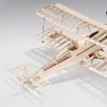 How to build an airplane out of wood How to make an airplane out of wood
 DIY paper machine (diagrams, templates)