Surface waste water calculation technique. Download a methodological manual. Recommendations for the calculation of systems for collecting, leading and cleaning the surface runoff of residential territories, enterprise sites and determining the conditions for the release of it into water bodies. Computing
Today we will analyze how to produce the hydraulic calculation of the heating system. After all, to this day, the practice of designing heating systems for the Nativity is applied. This is fundamentally incorrect approach: without prior calculation, we will decide the plate of the material consideration, provoking abnormal modes of operation and make it possible to achieve maximum efficiency.
Objectives and objectives of hydraulic calculation
From a engineering point of view, the liquid heating system seems to be a rather complex complex that includes heat generation devices, its transportation and isolation in heated rooms. The ideal mode of operation of the hydraulic heating system is considered to be such in which the coolant absorbs the heat from the source and transmits it with a room atmosphere without losses during the movement process. Of course, such a task is visible completely unattainable, but a more thoughtful approach allows you to predict the behavior of the system in various conditions and as much as possible to the reference indicators. This is the main goal of designing heating systems, the most important part of which hydraulic calculation is considered to be.
The practical goals of hydraulic calculation are as follows:
- Understand how speed and in which the coolant is moving in each system node.
- Determine what impact has the change in the mode of operation of each of the devices to the entire complex as a whole.
- Set which performance and performance characteristics of individual nodes and devices will be sufficient to perform their functions with a heating system without significant rise in prices and ensure unreasonably high reliability stock.
- Ultimately - provide a strictly dosed distribution of thermal energy in various zones of heating and ensure that this distribution will be maintained with high constancy.

It can be said more: without at least the basic calculations it is impossible to achieve an acceptable stability of the work and durable use of equipment. Modeling the action of the hydraulic system, in fact, is a basis on which all further project development is built.
Types of heating systems
The tasks of engineering calculations of this kind are complicated by a high variety of heating systems, both in terms of scale and configuration plan. There are several types of heating junctions, each of which has its own patterns:
1. Two-pipe stubble systemsand the most common version of the device, well-suitable for organizing both central and individual heating circuits.


The transition from the heat engineering calculation to the hydraulic is carried out by the introduction of the concept of mass flow, that is, some mass of the coolant caused to each section of the heating circuit. The mass flow is the ratio of the required thermal power to the product of the specific heat capacity of the coolant to the temperature difference in the feed and return pipeline. Thus, on the sketch of the heating system, the key points for which the nominal mass flow is indicated. For convenience, in parallel, the volumetric flow is determined, taking into account the density of the coolant used.
G \u003d Q / (C (T 2 - T 1))
- Q - necessary thermal power, W
- c is a specific heat carrier heat, for water received 4200 J / (kg · ° C)
- Δt \u003d (T 2 - T 1) - temperature difference between feed and reverse, ° C
The logic here is simple: To deliver the required amount of heat to the radiator, you need to first determine the volume or mass of the coolant with a given heat capacity passing through the pipeline per unit of time. To do this, it is required to determine the speed of the coolant in the circuit, which is equal to the ratio of the volume flow to the cross-section of the internal passage of the pipe. If the rate calculation is maintained relative to the mass flow, the denominator must add the density value of the coolant:
V \u003d g / (ρ · f)
- V - the speed of the coolant, m / s
- G - coolant consumption, kg / s
- ρ - density of the coolant, can be taken for water 1000 kg / m 3
- f - The pipe cross section is located according to the formula π- · R 2, where R is the inner diameter of the pipe, divided into two
Data on consumption and speed is necessary to determine the conditional passage of the pipes of the junction, as well as the supply and pressure of circulation pumps. The forced circulation devices must create an overpressure that allows you to overcome the hydrodynamic resistance of the pipes and the shut-off valves. The greatest complexity is the hydraulic calculation of systems with natural (gravitational) circulation, for which the required excess pressure is calculated by the speed and degree of volume expansion of the heated coolant.
Pressure loss and pressure
The calculation of the parameters according to the ratios described above would be sufficient for ideal models. In real life and volumetric stream, and the coolant speed will always differ from the calculated systems at different points of the system. The reason for this is the hydrodynamic resistance to the movement of the coolant. It is due to a number of factors:
- Forces of friction of the coolant about the walls of the pipes.
- Local resistances of the flow, formed fittings, cranes, filters, thermostatic valves and other reinforcement.
- The presence of ramifications of the connecting and branching types.
- Turbulent twistings on turns, narrowings, extensions, etc.

The task of finding the drop in pressure and speed in different parts of the system is considered the most difficult, it lies in the field of calculations of hydrodynamic media. Thus, the friction forces of the fluid on the inner surface of the pipe are described by a logarithmic function that takes into account the roughness of the material and kinematic viscosity. With the calculations of turbulent twists, it is still more difficult: the slightest change in the profile and the shape of the channel makes each separate situation unique. To facilitate the calculations, two reference ratios are introduced:
- Kvs. - characterizing the bandwidth of pipes, radiators, separators and other sections approximate to linear.
- To ms. - Determining local resistance in various reinforcement.
These coefficients are indicated by pipe manufacturers, valves, cranes, filters for each individual product. The coefficients are quite easy to use: to determine the loss of pressure, the CMC is multiplied by the ratio of the square of the coolant speed of the coolant to the double value of speeding acceleration:
ΔH ms \u003d to MS (V 2 / 2G) or ΔP MS \u003d K MS (ρV 2/2)
- ΔH ms - pressure loss on local resistances, m
- ΔP MS - pressure loss on local resistances, Pa
- To MS - local resistance coefficient
- g - Acceleration of free fall, 9.8 m / s 2
- ρ - density of the coolant, for water 1000 kg / m 3
The pressure loss on linear sections is the ratio of the bandwidth of the channel to the well-known bandwidth coefficient, and the result of the division must be erected into the second degree:
P \u003d (G / KVS) 2
- P - pressure loss, bar
- G - actual coolant consumption, m 3 / hour
- KVS - bandwidth, m 3 / hour
Pre-balancing system
The most important final purpose of the hydraulic calculation of the heating system is the calculation of such bandwidth values, in which in each part of each heating circuit flows a strictly dosed amount of heat carrier with a specific temperature than the normalized heat release on heating devices is provided. This task only seems complicated at first glance. In fact, balancing is performed by adjusting valves that limit the duct. For each valve model, it is indicated as the KVS coefficient for fully open state and the KV coefficient chart for different degrees of opening the adjustment rod. By changing the bandwidth of the valves, which, as a rule, are installed at the points of connection of heating devices, it is possible to achieve the desired distribution of the coolant, and hence the amounts of heat transferred to them.

There is, however, a small nuance: when the bandwidth changes at one point of the system, not only the actual flow rate on the sector under consideration changes. Due to the reduction or increase in the duct, the balance is changed in all other contours. If you take two radiator with different thermal power for example connected in parallel with the ongoing movement of the coolant, then with an increase in the bandwidth of the device standing in the chain first, the second will receive less heat carrier due to an increase in the difference in the hydrodynamic resistance. On the contrary, with a decrease in duct due to the adjustment valve, all other radiators standing on the chain further will receive a larger coolant volume automatically and will need additional calibration. For each type of wiring, balance the principles of balancing.
Software complexes for calculations
It is obvious that the execution of calculations is manually justified only for small heating systems that have a maximum of one or two contours with 4-5 radiators in each. More complex heat heating systems over 30 kW require a comprehensive approach when calculating hydraulics, which expands the range of tools used far beyond the pencil and sheet of paper.

To date, there is a fairly large number of software provided by the largest manufacturers of heating equipment, such as Valtec, Danfoss or Herz. In such software complexes, the same methodology that has been described in our review is used to calculate the hydraulics behavior. First, in the visual editor, an exact copy of the designed heating system is simulated, for which data on thermal power, the type of heat carrier, the length and the height of the pipelines used, used by the reinforcement, radiators and cooler coils are indicated. In the library of the program there is a wide range of hydraulic devices and reinforcements, for each product, the manufacturer has determined the operating parameters and basic coefficients in advance. If you wish, you can add third-party samples of devices if the desired list of characteristics is known for them.

In the work finals, the program makes it possible to determine the appropriate conditional passage of pipes, pick up sufficient supply and pressure of circulation pumps. The calculation is completed by balancing the system, while during simulation of the hydraulics, the dependences and the impact of changes in the bandwidth of one node of the system for all others take place. Practice shows that the development and use of even paid software products is cheaper than if the execution of the calculations was instructed to contract specialists.
Introduction1 area of \u200b\u200buse
2. Legislative and regulatory documents
3. Terms and definitions
4. General provisions
5. Qualitative characteristic of surface runoff from residential areas and enterprises
5.1. Choosing priority indicators of pollution of surface runoff in the design of wastewater treatment plants
5.2. Determination of the estimated concentrations of pollutants when the surface flow for cleaning and released into water bodies
6. Systems and structures of surface runoff displacement with residential areas and enterprises sites
6.1. Systems and schemes for surface sewage
6.2. Determination of the estimated costs of rain, melting and drainage waters in rain sewer collectors
6.3. Determination of the estimated wastewater costs of the sedipant sewage system
6.4. Regulation of wastewater costs in the rain sewage network
6.5. Pumping Surface Stream
7. Calculated surfaces of surface wastewater from residential areas and fields of enterprises
7.1. Determination of average annual volumes of surface wastewater
7.2. Determination of the calculated volumes of rain wastewater assigned to cleaning
7.3. Determination of the estimated daily volumes of melt waters allowed for cleaning
8. Determination of the estimated productivity of surface drain wastewatering structures
8.1. Current productivity of accumulative treatment facilities
8.2. Calculation productivity of flow-up treatment facilities
9. Terms of surface runoff with residential areas and enterprises sites
9.1. General provisions
9.2. Determination of standards for permissible discharge (VAT) of substances and microorganisms when producing surface wastewater into water bodies
10. Claiming surface runoff
10.1. General provisions
10.2. Selection of type of treatment facilities on the principle of water flow control
10.3. Basic technological principles
10.4. Cleaning the surface runoff from large mechanical impurities and trash
10.5. Separation and regulation of runoff on sewage treatment plants
10.6. Cleaning the drain from heavy mineral impurities (sandowing)
10.7. Battery and preliminary lightening of drain by static settling
10.8. Reagent surface flow treatment
10.9. Cleaning surface runoff with reagent settling
10.10. Cleaning surface drain reagent flotation
10.11. Cleaning surface drain by contact filtering method
10.12. Superficial UK filtration
10.13. Adsorption
10.14. Biological cleaning
10.15. Ozonization
10.16. Ion exchange
10.17. Barbecue processes
10.18. Disinfection of surface drain
10.19. Handling of technological processes for cleaning surface sewage
10.20. Basic requirements for monitoring and automating technological processes of cleaning surface wastewater
Bibliography
Appendix 1. The value of rain intensity
Appendix 2. Parameter values \u200b\u200bto determine the calculated costs in rain sewer collectors
Appendix 3. Map of zoning the territory of the Russian Federation on the layer of Melochal
Appendix 4. Map of zoning the territory of the Russian Federation by the coefficient with
Appendix 5. Methods for calculating the volume of the tank to regulate the surface runoff in the rain sewage network
Appendix 6. Methods for calculating pumping stations for pumping surface drain
Appendix 7. Methods for determining the maximum daily layer of rainlations for residential territories and enterprises of the first group
Appendix 8. Methods of calculating the daily layer of precipitation with a given probability of exceeding (for enterprises of the second group)
Appendix 9. Normal deviations from the average value of the ordinate logarithmically normal distribution curve F with different values \u200b\u200bof the security and asymmetry coefficient
Appendix 10. Normal deviations of the ordinate binominal distribution curve F with different values \u200b\u200bof the availability and asymmetry coefficient
Appendix 11. The average daily layers of precipitation of the NWR, the coefficients of variation and asymmetry for various territorial areas of the Russian Federation
Appendix 12. Methods and an example of calculating the daily volume of melt waters assigned to clean
Federal Agency of the Russian Federation
Construction and housing and communal services
(ROSSTROY)
Introduction Section 3. General Section 4. Qualitative characteristic of surface runoff from residential areas and enterprises 4.1. Choosing priority indicators of pollution of surface runoff in the design of wastewater treatment plants 4.2. Determination of the estimated concentrations of pollutants when the surface flow of cleaning and released into water bodies Section 5. Quantitative characteristics of the surface runoff from residential areas and platforms of enterprises 5.1. Definition of average annual volumes of surface wastewater 5.2. Determination of the calculated volumes of surface wastewater when they are allowed to clean 5.3. Determining the estimated costs of rain and melt waters in rain sewer collectors 5.4. Determination of the estimated costs of surface runoff when removing cleaning and in water bodies Section 6. Terms of surface runoff with residential areas and enterprises sites 6.1. General provisions 6.2. Determination of PDS regulations of pollutants when producing surface sewage into water bodies Section 7. Systems and facilities for collecting and disintegration of surface runoff from residential areas and enterprises 7.1. Schemes for collecting and dischargeing surface drain 7.2. Constructions for the control of surface runoff when assuming to clean and methods for their calculation 7.3. Pumping Surface Stream 7.4. Determination of the estimated productivity of wastewater treatment facilities Section 8. Cleaning Surface Stream from residential areas and fields of enterprises 8.1. General provisions 8.2. Mechanical cleaning 8.3. Wastewater treatment with flotation 8.4. Filtration 8.5. Reagent cleaning of surface drain 8.6. Biological cleaning 8.7. Ion exchange 8.8. Adsorption 8.9. Ozonization 8.10. Sidel treatment 8.11. Disinfection of surface drain Legend: BIBLIOGRAPHY Appendix 1 Classification of the regions of the Russian Federation depending on climatic conditions Appendix 2 Rain Intensity Values \u200b\u200bQ20 Appendix 3 values \u200b\u200bof parameters N, MR, γ to determine the estimated costs in rain sewer collectors Appendix 4 Average rainy duration per day with precipitation Appendix 5 Methods for constructing a chart of the probability distribution function of the daily rain layers and an example of calculating the daily layer of rain with a given period of one-time exceeding< 1 года Appendix 6 Method for calculating the daily layer of precipitation with a given probability of exceeding Appendix 7 Surface Stream Control Schemes and Methods for Calculating Wastewater Consumption Allocated to Cleaning and Water Objects Appendix 8 Methods for calculating pumping stations for pumping surface drain |
Introduction
3. Rules for the use of municipal water supply and sewage systems in the Russian Federation.
Recommendations are developed by the team of SSC SOCS specialists FSUE NII Vodgeo under the scientific leadership of Doctor of Technical Sciences as part of: Candidates of Technical Sciences, Doctor of Technical Sciences, Engineer, Candidates of Technical Sciences, Doctor of Technical Sciences.
When developing recommendations, data of natural studies received by the specialists of the Acrch them were taken into account. , VNIIVO and a number of sectoral research organizations at enterprises of various industries, as well as data experience of the operation of surface runoff treatment facilities with territories of cities and industrial enterprises planned and built over the past 30 years.
The recommended calculation of the collection and diversion systems of surface wastewater is based on the limit intensity method developed and later developed by an engineer, a doctor of technical sciences, a candidate of technical sciences, doctors of technical sciences and A. M. Kurgan.
The authors are special thanks to the head of the SoyuzvodocanalProek State Unitary enterprise, the candidate of technical sciences for the assistance provided in the preparation of recommendations, as well as participants in the seminar Research Institute of Vodgeo "Systems of the collection, leading and cleaning of surface runoff from residential territories of cities and industrial enterprises" (April 6-7, 2005 , Moscow), devoted to the new edition of the recommendations, for the comments and wishes expressed.
1 With the release of these recommendations, "Provisional recommendations for the design of structures for cleaning the surface runoff from the territories of industrial enterprises and the calculation of the conditions for the release of it into water bodies", published by VNII VOGGEO in 1983, are lost.
Section 1. Legislative and Regulatory Documents
1. Water Code of the Russian Federation of November 16, 1995.
3. Rules for the protection of surface waters. - M., 1991.
4. SanPine 2.1.5.980-00. Hygienic requirements for the protection of surface waters.
5. GOST 17.1.3.13-86. General requirements for the protection of surface water from contamination.
6. Rules for the use of municipal water supply and sewage systems in the Russian Federation. Approved by the Decree of the Government of the Russian Federation of February 12, 1999 No. 000.
7. SNiP 2.04.03-85. Sewage. External networks and facilities.
8. Snip 23-01-99. Construction climatology.
9. GOST 17.1.1.01-77. Protection of Nature. Hydrosphere. Use and protect water. Basic terms and definitions.
10. GOST 17.1.3.13-86. Protection of Nature. Hydrosphere. Classification of water bodies.
11. Sanpin 2.2.1 / 2.1.1.1200-03. Sanitary and epidemiological rules and regulations.
12. GOST 27065-86. Water quality. Terms and Definitions.
13. GOST 19179-73. Sushi hydrology. Terms and Definitions.
14. List of fisheries standards: extremely permissible concentrations (MPC) and approximately safe levels of exposure (shoes) of harmful substances of water of water bodies that have a fishery appointment. APPROVED by order of Roskomgrivosti dated June 28, 1999 No. 96.
15. GN 2.1.5.1315-03. Maximum permissible concentrations (MPC) of chemicals in water of water bodies of economic and drinking and consumer water use. Hygienic standards. Approved and put into effect by the Resolution of the Chief State Sanitary Doctor of the Russian Federation of April 30, 2003 No. 78.
16. GN 2.1.5.1316-03. Approximately permissible levels (ODU) of chemicals in water of water and drinking and cultural water use. Hygienic standards. Approved and put into effect by the Resolution of the Chief State Sanitary Doctor of the Russian Federation of 01.01.01 No. 78.
Section 2. Terms and Definitions
For the purposes of this document, the following terms and definitions are applied:
Accumulating capacity (Surface drain drive) - construction for the reception, collection and averaging of the consumption and composition of surface wastewater from residential areas and enterprises sites in order to follow their subsequent cleaning.
Regulatory documents are given, regulating the design of the design systems for the leading and purification of surface (raindrop, melting, polyvochetic) wastewater from residential areas and platforms of enterprises, as well as comments on the provisions of the joint venture 32.13330.2012 "Sewerage. External networks and structures "and" Recommendations for the calculation of systems for collecting, leading and cleaning a surface runoff from residential areas and sites of enterprises and determining the conditions for the release of it into water bodies "(OJSC NII Vodgeo). The specified documents allow for a discharge to clean the most contaminated part of the surface runoff in the amount of at least 70% of the annual flow rate for residential territories and sites close to them for pollution, and all the volume of flow from the fields of enterprises whose territory can be contaminated with specific substances with toxic properties or significant content of organic substances. The generally accepted practice of designing engineering structures of separate and wide sewage systems, allowing short-term discharge of parts of the drain when intensive (storm) rare repeatability rains through separation chambers (livnesbrosis) into a water facility. Situations related to the failures of the territorial departments of state examination and Rosrybolov are considered in coordinating the implementation of activities on the projected capital construction objects on the basis of Article 60 of the Water Code of the Russian Federation prohibiting the wastewater and neutralization and neutralization.
Keywords
List of cited literature
- Danilov O. L., Kostyuchenko P. A. Practical manual for the choice and development of energy-saving projects. - M., ZAO TEKHNOPROMSTROY, 2006. P. 407-420.
- Recommendations for calculating systems for collecting, leading and cleaning the surface runoff from residential areas, enterprises sites and determining the conditions for the release of it into water bodies. Supplement to SP 32.13330.2012 "Sewerage. External networks and facilities "(updated edition SNiP 2.04.03-85). - M., OJSC NII Vodgeo, 2014. 89 p.
- Vereshchagin L. M., Menshutin Yu. A., Shvetsov V.N. On the regulatory framework for the design of the system of leading and purification of surface wastewater: IX Scientific and Technical Conference "Yakovlevsky Readings". - M., MGSU, 2014. P. 166-170.
- Molokov M. V., Shifrin V. N. Cleaning the surface runoff from the territories of cities and industrial sites. - M.: Stroyzdat, 1977. 104 p.
- Alekseev M. I., Kurganov A. M. Organization of the leading of the surface (rain and thaela) runoff with urbanized territories. - M.: Publishing House of the DC; St. Petersburg, SPbgas, 2000. 352 p.
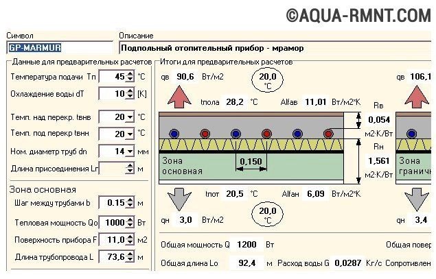
After collecting the source data, the determination of thermal loss of the house and the power of the radiators remains the hydraulic calculation of the heating system. Properly performed, it is a guarantee of correct, silent, stable and reliable operation of the heating system. Moreover, it is a way to avoid extra investment and energy costs.
Calculations and work that you need to perform in advance
Hydraulic calculation is the most time consuming and complex design.
- First, the balance of heated rooms and premises is determined.
- Secondly, it is necessary to choose the type of heat exchangers or heating devices, as well as perform their placement on the plan of the house.
- Thirdly, the calculation of the heating of a private house assumes that the choice is already made regarding the configuration of the system, types of pipelines and fittings (regulating and shut-off).
- Fourth, a drawing system should be made. It is best if it is aksonometric scheme. It should contain numbers, length of calculated sections and thermal loads.
- Fifth, the main circulation ring is installed. This is a closed loop, which includes serial sections of the pipeline directed to the instrument rink (when considering a single-tube system) or to the remote heating device itself (if a two-pipe system occurs) and back to the heat source.
The calculation of heating in a wooden house is performed by the same scheme as in a brick or in any other country cottage.
The procedure for conducting calculations
Hydraulic calculation of the heating system involves the solution of the following tasks:
- determining the diameters of the pipeline on different segments (however, economically appropriate and recommended coolant movement speeds are taken into account);
- calculation in different parts of hydraulic pressure losses;
- hydraulic linkage of all branches of the system (hydraulic instrument and other). It involves the use of regulatory reinforcement, which allows for dynamic balancing with non-stationary hydraulic and thermal modes of the functioning of the heating system;
- consumption of the coolant and calculation of pressure losses.
Are there free software for calculations?
To simplify the calculation of the private home heating system, you can use special programs. Of course, they are not as many graphic editors, but there is still a choice. Some are distributed free of charge, others in demo versions. In any case, make the necessary calculations one or twice will work without material investments.
Software "OVENTROP CO"
Free Software "OVENTROP CO" is intended to perform hydraulic calculation of the heating of a country house.
The OVENTROP CO program is designed to provide graphical assistance at the stage of the preparation of the heating project. It allows the hydraulic calculation for one-tube, and for a two-pipe system. It is easy to work in it and convenient: there are already ready-made blocks, controls errors, a huge catalog of materials
Based on preliminary settings and selection of heating devices, pipelines and reinforcements, you can design new systems. In addition, it is possible to adjust the existing scheme. It is carried out by selecting the capacity of the equipment already available in accordance with the needs of heated rooms and premises.
Both of these options can be combined in this program, allowing you to regulate existing fragments and design new ones. In any embodiment, "OVENTROP CO" selects the adjustment settings. In terms of the implementation of hydraulic calculations, this program has ample opportunities: from the selection of pipeline diameters before analyzing the water consumption in the equipment. All results (tables, diagrams, drawings) can be printed or transfer to Windows Wednesday.
INSTAL-THERM HCR Software
The "Instal-Therm HCR" program allows you to calculate the system of radiator and surface heating.
It comes with Instalsystem Tece, which includes three more programs: Instal-San T (for designing cold and hot water), Instal-Heat & Energy (for calculating heat loss) and Instal-Scan (for scanning drawings).

The "Instal-Therm HCR" program is equipped with advanced materials catalogs (pipes, water consumers, fittings, radiators, thermal insulation and locking fittings). The results of the calculations are issued as a specification for the materials and products offered by the program. The only lack of a trial version - it is impossible to withdraw it to print
Computational capabilities "Instal-therm HCR": - selection of pipe diameter and reinforcement, as well as tees, shaped products, distributors, passage couplings and thermal insulation of the pipeline; - determination of the height of the lifting of pumps located in the mixers of the system or on the plot; - hydraulic and thermal calculations of heating surfaces, automatic determination of the optimal input temperature (power); - Selection of radiators, taking into account the cooling in the pipelines of the working agent.
The trial version can be used for free, but it has a number of restrictions. First, as in most conditionally free programs, the results cannot be printed, as well as export them. Secondly, in each of the package applications, you can create only three projects. True, you can change them as much as you like. Thirdly, the created project is stored in a modified format. Files with such an extension none of the trial nor even the standard version will not read.
Software "Herz C.O."
The program "Herz C.O." is free. With it, it is possible to make hydraulic calculation and a single-pipe, and a two-pipe heating system. An important difference from others is the possibility of performing calculations in new or reconstructed buildings, where a glycolic mixture protrudes as a coolant. This software has a certificate of compliance of CMSPS LLC.
"HERZ C.O." Provides the user to the following options: the selection of pipes in diameter, settings of regulators of the pressure difference (branching, the base of the drain); analysis of water consumption and determination of pressure losses in equipment; Calculation of hydraulic resistance of circulating rings; accounting for the necessary prestiges of thermostatic valves; Reducing in circulation rings of overpressure by selecting the valve settings. For user convenience, a graphic data entry is organized. The results of the calculations are derived in the form of circuits and floor plans.

Schematic representation of the results of calculations in Herz C.O. It is much more convenient for the specification for materials and products, in the form of which are derived from the results of calculations in other programs.
The program has a developed contextual help providing information on individual commands or inserted indicators. Multi-digital mode of operation allows you to simultaneously view multiple data types and results. Working with a plotter and printer is very simply organized, you can preview the displayed pages before printing.
Program "Herz C.O." Equipped with a convenient feature of automatic search and diagnostics of errors in tables and in diagrams, as well as rapid access to catalog of reinforcement, heating devices and pipes
Modern control systems with a constantly changing thermal regime require equipment for monitoring changes and regulation.
Make a choice of regulatory reinforcement, do not own the situation on the market, it is very difficult. Therefore, in order to make the calculation of heating on the area of \u200b\u200bthe whole house, it is better to use the software application with a large library of materials and products. Not only the operation of the system itself, but also the amount of investment, which will be required for its organization depends on the correctness of the data obtained.
 How to return the love of her husband to his wife - Tips of the psychologist
 Why you can not give icons