Box for connecting wires on the street. Connecting wires in a junction box. Main function of distribution box
The electrical network got its name for a reason. It covers all rooms like a web, ensuring the operation of the equipment. To distribute energy between individual connection points (sockets, switches), junction boxes are used. One cable goes into them, but several come out. A prerequisite for safe operation of the electrical network is to twist the wires correctly and accurately. To do this, you can use different methods.
To better understand how to do twisting correctly, let’s figure out what options exist, the order, and the features of their implementation. Electricity is considered one of the communications that “do not forgive” mistakes. The result of illiterate actions is damage to the device, short circuit, or fire. Beginning craftsmen often ask: is it possible to connect the wires in the junction box yourself? Of course, but before that you should take the time to study the rules and features of electrical work.
Wire connection methods
There are different ways of tightening wires in a junction box: crimping, welding, soldering, various clamps. Some require more time, special materials, and equipment. Others are easier to implement, but poor execution significantly reduces their reliability.
Twisting is popular among folk craftsmen. The PUE classifies it as an unreliable method that does not guarantee reliable contact. It is usually used as a temporary option, for example, when checking the functionality of a circuit. In addition, it is considered preferable for sagging, loose networks. Advantages:
- ease of execution;
- minimum tools;
- Easy to disconnect if necessary.
One of the disadvantages is the difficulty of working with wires of different sections: the difference in resistance leads to heating of the insulation, its gradual melting. They try not to use this method for multi-core cables, since the probability of a circuit break is high.
Do not twist copper and aluminum wires: the result will be unreliable, the point of contact will become a source of increased resistance.
The easiest way to twist wires is by twisting the previously stripped ends together. The tools you will need are a knife and pliers. First, a section of the core 5 cm long is cleared of insulation. The bare ends are crossed, bringing the individual parts as close as possible. Then use pliers to rotate the crosshair, bend it in any direction parallel to the main line, and isolate it.
Types of wire connections
You can use another option, when the stripped ends are folded in the middle and interlocked. Then the wires are wrapped together. For reliability, they are crimped with pliers and insulated. Electricians know many methods of twisting: parallel or serial bandage, groove. Correct twisting should ensure the most complete fit of the cores.
Electrical tape is usually used for insulation. It is necessary that it extends at least 2-3 cm onto the insulation. You can use a thermotube. It is first put on the cable, then moved, covering the contact point. The tube should tightly grip the wiring, so it is heated a little.
For crimping, you will need a special sleeve, selected for the size of the bundle and the cable material. The stripped ends of the core are inserted into the sleeve, crimped with press pliers, and insulated.
In terms of reliability and quality, welding gives the best results. In fact, they get a one-piece structure that is protected from oxidation and rupture. To perform this you will need a welding machine, carbon electrode, and flux. Step-by-step implementation instructions:
- strip the ends of the cable from insulation, bring them to a shine with sandpaper;
- twist the wiring;
- fill the recess of the electrode with flux;
- weld the contact point.
Clean the resulting “ball” from flux and coat it with varnish. Similar actions are performed when soldering. Here the contact is provided by solder melted using a soldering iron.
Twists of copper and aluminum wires
A lot has been written about why copper and aluminum cannot be combined with each other. The consequence of such contact is its heating, subsequent combustion. There are several reasons for this behavior of metals:
- Difference in thermal expansion coefficients. Metals expand differently when heated and contract when cooled. Therefore, their connection gradually deteriorates.
- Formation of an oxide film on aluminum. The film prevents the passage of current, the conductor heats up, and the connection is gradually destroyed.
- Violation of the aluminum structure during electrolysis. Copper and aluminum form a galvanic couple. Under the influence of moisture, dissociation of ions begins, which leads to the destruction of the metal. The resulting shells and voids conduct current poorly and cause heating.

The presence of aluminum wiring in houses leads to the need to combine it with new copper conductors. Using simple rules, you can avoid heating the contact and ensure its reliability. When performing twisting, it is important to wrap the conductors around each other. The number of turns is more than 3 for a thick wire, at least 5 for a thin wire (less than 1 mm). The finished connection is sealed with a protective varnish that is resistant to water.
Maximum reliability is ensured by a method in which the copper is pre-coated with solder. This creates reliable contact between single and multi-core conductors. To do this, the multi-core wire must first be tinned with solder, it will become single-core.
To make the contact detachable, use a bolt, nuts, and spring washers. All elements are placed on the rod one by one, avoiding the combination of copper wires and aluminum. For example: a conductor with a diameter of less than 2 mm will fit perfectly on an M4 bolt.
The development of electrical engineering has brought new comfortable ways of working with different materials. An example is a terminal block. Its advantages:
- comfortable;
- reliable;
- eliminates contact between bare areas.
The end of the core is stripped of insulation (approximately 5-10 mm), inserted into the hole, and clamped with a screw. The terminal box is indispensable when restoring a broken circuit or connecting a chandelier. It can only be placed in the wall in a junction box.
The Wago terminal block is deservedly popular. It can be disposable or reusable (with a lever). The terminal block works simply: insert the cable with force, it is fixed. Disadvantage: more expensive than other traditional means.
The danger of twisting copper and aluminum wires
Twisting wires of different sections
Often the master is faced with the task of connecting wires of different diameters in a junction box. This can be done in several ways: twisting followed by soldering (welding), screw terminals, self-clamping terminals, bolts, nut-type couplers, tinned copper lugs.
The easiest way is to twist wires in a box that are similar in thickness (for example, 4 and 2.5). With a large difference, it is difficult to ensure high-quality contact. The wires must wrap tightly around each other, then they are welded or sealed. A strong connection will last for many years without complaints.
A reliable contract between conductors of adjacent cross-sections is created by the ZVI screw clamp. The cables are inserted from different sides, each clamped with a separate screw. The choice of clamp is made taking into account the characteristics of the conductors and the permissible current. Execution principle:
- strip the ends by 2-3 cm;
- insert them into the box;
- tighten the screws.
If the wires have a large cross-section, you can twist them using a Wago self-clamping terminal. Its peculiarity is the presence of special sockets for each core. Marking the terminal body will help you figure out how many wires you can twist and what cross-section.
Long-lasting contact of the wires in the junction box is guaranteed by a bolted connection. It allows you to fasten two, three or more wires using nuts, washers, bolts. Step-by-step mounting instructions:
- strip the core by 3 cm (you should get a full turn);
- prepare a ring from the core according to the diameter;
- put a washer on the bolt, a ring of one conductor, another washer, a ring of the second conductor;
- Place the next washer and tighten with the nut.
This way you can connect several wires together. Their number is limited only by the length of the rod.
The question often arises: how to twist the wires together to branch from the main line in the distribution panel? The solution most often is a branch compression, in common parlance - a “nut”. It allows you to branch a line from it without cutting the main line. To do this, the desired place in the main part is cleared of insulation, a clamp is attached, and an additional “branch” is inserted. It can also be used to connect two separate cables. When choosing a “nut”, you need to know the cross-section of the main cable and branches. Using compression, you can connect a copper wire to an aluminum one.
The body of the “nut” is not sealed. To protect it from moisture, dust, and debris, it should be insulated.
The compression connection procedure is simple:
- disassemble the housing by removing the retaining rings with a screwdriver;
- strip the insulation (the length corresponds to the dimensions of the die);
- loosen the fastening;
- insert the cores into special grooves on the dies;
- carefully (without overtightening) tighten the bolts;
- place the die in the body;
- close the housing, install retaining rings.
To work with a thick cable, you will need copper lugs and crimping pliers. The connection turns out to be bulky, so you will need to provide enough space in the box for it. A ferrule is put on each core, crimped, secured with a bolt and nut, washer, and insulated (with electrical tape, heat pipe)
Reliable wire connection
Errors when twisting wires
A common mistake when twisting is to wrap one wire around another. This option does not provide the required mechanical strength. The conductors should wrap around each other evenly. It is unacceptable to screw a thin conductor onto a thick one; a tight fit will not be achieved.
The length of the twist depends on the cross-section of the wires. It should be at least 3-5 cm. Options for clutching in a ring, loose fit, or not twisted are unacceptable.
Direct connection of copper with aluminum leads to rapid destruction of the contact. Craftsmen often forget to install an intermediate plate, which will prevent direct contact of metals.
uzotoka.ru
Soldering and welding of wires
Modern requirements set out in regulatory documents (PUE) prohibit splicing electrical wiring by conventional twisting, regardless of the insulation method. But if the twisted wires are soldered or welded, the contact will be reliable and will comply with all the rules.

Let's look at how to connect current-carrying parts of cables in a junction box using desoldering:
- Remove the insulation from the wires at a distance of about 3 cm and sand them with fine sandpaper.
- Twist the strands tightly together using pliers.
- Using rosin and solder (POS 61 brand is suitable), carefully tin the connection so that molten tin flows into the space between the wires.
- Insulate the joint with heat shrink tubing or wrap it with adhesive tape.

Note. Soldering copper is not difficult, but oxidized aluminum sometimes has to be treated with acid.
Connecting wires by welding is performed in the same manner, only instead of a soldering iron, a device with a carbon electrode is used. A special recess is made in it, into which flux is poured, after which the device is plugged into the network, and the electrode is pressed against the twist until an influx is formed in the form of a small ball.

The advantage of this method is the durability of the joint and the ability to connect wires of different sections, including multi-core ones, in the junction box. Due to its reliability, the connection is successfully used in power lines with various loads, but it has some disadvantages:
- Do not solder or weld copper conductors with aluminum ones;
- This connection is permanent and in case of alteration according to a new scheme, the contacting areas have to be bitten off.
Reference. Soldering contacts is often used when installing low-current networks, for example, telephone cables and radio points.
Disconnection by crimping method
In this case, the reliability of the connection of the wires in the junction box is ensured using sleeves made of the same metal as the conductors - aluminum or copper. To complete the job, you will also need special press pliers, shown in the photo.

Note. Some would-be electricians practice crimping sleeves with ordinary pliers, which is unacceptable. Correct fixation of contacts is carried out only with pliers.
Now about how to connect electrical wires in a box in this way:
- Perform termination and twisting of wires as described above.
- Place a sleeve over the twisted ends (it should be matched to the diameter and fit tightly).
- Crimp the sleeve with pliers in two places.
- If the distribution boxes are installed outdoors, the connection is insulated with heat shrink, ensuring tightness. PVC insulating tape can be used indoors.

This joining option has the same pros and cons as welding: you can connect wiring of different sections and numbers of wires, but you cannot connect contacts made of dissimilar metals.
Application of connecting terminal blocks
Terminals for quick connection of wires are of 2 types:
- screw clamps in the form of blocks;
- Wago type self-clamping connectors
The technology for splicing electrical cables using terminal devices is quite simple. The wires need to be exposed only 1 cm and inserted into the clamps. In the first case, the cores are fixed with screws, in the second - with levers or automatic latches. By the way, terminals with latches are disposable, while terminals with levers are used repeatedly.

We list the advantages of screw terminal blocks:
- Fast and reliable docking.
- Ability to connect copper wiring to aluminum.
- Provides a detachable connection.
- Does not require additional insulation.
One of the disadvantages of the pads is their size. It happens that when there is a large accumulation of wires coming from several switches or sockets, the screw connector does not fit inside the junction box. Point two: single-core wires are fixed without problems, but multi-core wires are flattened with screws, which is not good. Therefore, it is better to pre-tin such ends.

Wago clamps, which allow you to connect up to 4 wires of the same cross-section, have the same advantages as screw terminals, but take up less space. In this case, the operation of disconnecting the entire junction box will take about 5 minutes, which is very convenient for installing electrical wiring. Judge for yourself: the bare end needs to be inserted into the clamp with pliers until it stops and that’s all.
Reference. Similar devices are often used for laying Internet cables and other low-current networks.

Since there are cheap products on the market from various Chinese manufacturers, self-clamping terminal blocks have acquired a dubious reputation. The fact is that in low-quality connectors, the contact weakens over time, causing them to overheat and melt. If you purchased original Wago products, then there will be no problems; in other cases, it is better not to take risks and connect only lighting wires with clamps (power supply to switches, chandeliers, and so on). Wire the sockets using a different method.
The master will tell you how to use self-clamping terminals correctly in his video:
Plastic PPE caps
The abbreviation SIZ stands for connecting insulating clamp. It is a cone-shaped cap made of plastic, which contains a steel spring with an anodized coating.
The technology for using the product is as follows:
- Remove the insulation from the wires to be connected to a distance of 2-3 cm.
- Gather the wires into one bundle and insert them into the cap until it stops.
- Applying force from the blind part, turn the cap by hand 2-3 turns. A traditional twist is formed inside, secured with a spring.

Such clamps are quick-release and reusable, provided that the spring was not damaged during dismantling. With their help, the connection in the box is made quite quickly, does not require insulation and does not take up much space.
Important point. In order for the PPE cap to provide reliable and durable contact, it must be selected according to the diameter corresponding to the total cross-section of the wires being connected. For the correct selection, use the table:

Details on how to connect wires in a junction box in various ways, including using caps, are described in the video:
Conclusion
Now, knowing the features of all methods of connecting contacts in a junction box, you can choose the best option and successfully apply it. Finally, let us mention another old method of connecting conductors - bolted, when the conductors are bent around the thread to the right side and pressed with a nut. But this option is practically not used due to the inconvenience and cumbersomeness of the connection, although it is considered reliable and complies with the PUE.
qustu.com
What is a junction box
From the electrical panel, the wires disperse throughout the rooms in the house or apartment. Each room, as a rule, has more than one connection point: there are several sockets and a switch. To standardize the methods of connecting wires and collect them in one place, distribution boxes are used (they are also sometimes called branch boxes or junction boxes). They contain cables from all connected devices, the connection of which occurs inside the hollow housing.
In order not to look for wiring during the next repair, it is laid according to certain rules that are prescribed in the PUE - Rules for the Construction of Electrical Installations.

Electrical wiring rules
One recommendation is to carry out all connections and branch wires in the junction box. Therefore, the wires are run along the top of the wall, at a distance of 15 cm from the ceiling level. Having reached the branch point, the cable is lowered vertically down. A distribution box is installed at the branch point. It is where all the wires are connected according to the required circuit.
According to the type of installation, junction boxes are either internal (for hidden installation) or external. Under the internal ones, a hole is made in the wall into which the box is built. With this installation, the cover is flush with the finishing material. Sometimes during the renovation process it is covered with finishing materials. However, such installation is not always possible: the thickness of the walls or finishing does not allow it. Then a box for external mounting is used, which is attached directly to the wall surface.

Some forms of junction boxes
The shape of the junction box can be round or rectangular. There are usually four conclusions, but there may be more. The terminals have threads or fittings to which it is convenient to attach a corrugated hose. After all, it is more convenient to lay wires in a corrugated hose or plastic pipe. In this case, replacing the damaged cable will be very simple. First, disconnect it in the distribution box, then from the consumer (socket or switch), pull it and pull it out. Tighten a new one in its place. If you lay it the old fashioned way - in a groove, which is then covered with plaster - you will have to drill into the wall to replace the cable. So this is the recommendation of the PUE, which is definitely worth listening to.
What do distribution boxes generally provide:
- Increased maintainability of the power supply system. Since all connections are accessible, it is easy to determine the area of damage. If the conductors are laid in cable channels (corrugated hoses or pipes), replacing the damaged section will be easy.
- Most electrical problems arise in the connections, and with this installation option they can be inspected periodically.
- Installing distribution boxes increases the level of fire safety: all potentially dangerous places are located in certain places.
- Requires less money and labor than laying cables to each outlet.
Wire connection methods
In a box, conductors can be connected in different ways. Some of them are more difficult to implement, others are easier, but if implemented correctly, they all provide the required reliability.
Twist
The most popular method among folk craftsmen, but the most unreliable. It is not recommended by the PUE for use, as it does not provide proper contact, which can lead to overheating and a fire. This method can be used as a temporary method, for example, to check the functionality of the assembled circuit, with mandatory subsequent replacement with a more reliable one.

Correct twisting of electrical wires
Even if the connection is temporary, everything must be done according to the rules. The methods for twisting stranded and single-core conductors are similar, but have some differences.
When twisting stranded wires, the procedure is as follows:
- the insulation is stripped to 4 cm;
- the conductors unwind by 2 cm (item 1 in the photo);
- connect to the junction of untwisted conductors (pos. 2);
- the veins are twisted with your fingers (position 3);
- the twist is tightened with pliers or pliers (pos. 4 in the photo);
- insulated (insulating tape or heat-shrinkable tubing placed before the connection).
Connecting wires in a distribution box with one core using twisting is easier. The conductors, stripped of insulation, are crossed and twisted with fingers along their entire length. Then take a tool (pliers and pliers, for example). In one, the conductors are clamped near the insulation, in the second, the conductors are intensively twisted, increasing the number of turns. The connection point is isolated.

Twist with pliers or pliers
Twist with mounting caps
Twisting is even easier using special caps. With their use, the connection is more reliably insulated and the contact is better. The outer part of such a cap is cast from flame retardant plastic; a metal conical part with a thread is inserted inside. This insert provides a larger contact surface, improving the electrical performance of the connection. This is a great way to connect two (or more) wires without soldering.
Twisting wires using caps is even simpler: 2 cm of insulation is removed, the wires are slightly twisted. A cap is put on them and turned with force several times until the metal is inside the cap. That's it, the connection is ready.

Connecting wires using a cap
Caps are selected depending on the cross-section and number of conductors that need to be connected. This method is more convenient: it takes up less space than conventional twisting, and everything fits more compactly.

Connecting conductors in a junction box with caps
Soldering
If you have a soldering iron in the house and you know how to handle it at least a little, it is better to use soldering. Before twisting, the wires are tinned: a layer of rosin or soldering flux is applied. The heated soldering iron is dipped in rosin and passed several times over the part that has been stripped of insulation. A characteristic reddish coating appears on it.

Soldered wires
After this, the wires are twisted as described above (twisting), then they take the tin on a soldering iron, heat the twist until the molten tin begins to flow between the turns, enveloping the connection and ensuring good contact.
Installers do not like this method: it takes a lot of time, but if you are connecting the wires in the junction box for yourself, spare no time and effort, but you will sleep peacefully.
Welding wires
If you have an inverter welding machine, you can use a welding connection. This is done on top of the twist. Set the welding current on the machine:
- for a cross section of 1.5 mm2 about 30 A,
- for a cross section of 2.5 mm2 - 50 A.
The electrode used is graphite (this is for welding copper). Using grounding pliers, we carefully cling to the upper part of the twist, bring the electrode to it from below, briefly touch it, achieving ignition of the arc, and remove it. Welding occurs in a fraction of a second. After cooling, the joint is insulated. Watch the video for the process of welding wires in a junction box.
Terminal blocks
Another connection of wires in the distribution box is using terminal blocks - terminal blocks, as they are also called. There are different types of pads: with clamps and screw ones, but, in general, the principle of their design is the same. There is a copper sleeve/plate and a wire fastening system. They are designed in such a way that by inserting two/three/four conductors into the right place, you connect them securely. The installation is very simple.
Screw terminal blocks have a plastic housing in which the contact plate is fixed. They are of two types: with hidden contacts (new) and with open contacts (old style). In any of them, a conductor stripped of insulation (length up to 1 cm) is inserted into the socket and clamped with a screw and a screwdriver.

Connecting wires in a junction box using terminal blocks
Their disadvantage is that it is not very convenient to connect a large number of wires in them. The contacts are arranged in pairs, and if you need to connect three or more wires, you have to squeeze two wires into one socket, which is difficult. But they can be used in branches with significant current consumption.
Another type of block is Vago terminal blocks. These are pads for quick installation. There are mainly two types used:

The peculiarity of these terminal blocks is that they can only be used at low currents: up to 24 A with a copper wire cross-section of 1.5 mm, and up to 32 A with a cross-section of 2.5 mm. When connecting loads with high current consumption, the wires in the junction box must be connected in a different way.
Crimping
This method is possible with special pliers and a metal sleeve. A sleeve is put on the twist, it is inserted into the pliers and clamped - crimped. This method is just suitable for lines with a large ampere load (such as welding or soldering). Watch the video for details. It even contains a model of a distribution box so it will be useful.
Basic wiring diagrams
Knowing how to connect the wires in the junction box is not everything. You need to figure out which wires to connect.
How to connect sockets
As a rule, the socket group runs on a separate line. In this case, everything is clear: you have three cables in the box, each with three (or two) conductors. The color may be the same as in the photo. In this case, usually brown is the phase wire, blue is neutral (neutral), and yellow-green is ground.

Wiring diagram for a socket in a distribution box
In another standard, the colors may be red, black and blue. In this case, the phase is red, blue is neutral, green is ground. In any case, the wires are collected by color: all of the same color in one group.
Then they are folded, stretched, and trimmed so that they are the same length. Do not cut short, leave a margin of at least 10 cm so that if necessary you can re-seal the connection. Then the conductors are connected using the chosen method.
If only two wires are used (in houses of old construction there is no grounding), everything is exactly the same, only there are two connections: phase and neutral. By the way, if the wires are the same color, first find the phase (with a probe or multimeter) and mark it, at least by wrapping a piece of electrical tape around the insulation.
Connecting a single-key switch
If there is a switch, the matter is more complicated. There are also three groups, but their connection is different. Eat
- input - from another junction box or from a panel;
- from the chandelier;
- from the switch.
How should the circuit work? Power - “phase” - goes to the switch key. From its output it is fed to the chandelier. In this case, the chandelier will light only when the switch contacts are closed (the “on” position). This type of connection is shown in the photo below.

Connecting a single-key switch in a distribution box
If you look carefully, this is what happens: the phase with a light wire goes to the switch. It leaves from another contact, but this time blue (do not mix it up) and connects to the phase wire that goes to the chandelier. Neutral (blue) and ground (if network) are twisted directly.
Connecting a two-gang switch
Connecting wires in a junction box with a two-button switch is a little more complicated. The peculiarity of this circuit is that a three-core cable must be laid to the switch for two groups of lamps (in a circuit without grounding). One wire is connected to the common contact of the switch, the other two to the key outputs. In this case, it is necessary to remember what color the conductor is connected to the common contact.

Connection diagram for two-button switch
In this case, the phase that has arrived is connected to the common contact of the switch. The blue wires (neutral) from the input and two lamps are simply twisted all three together. There are wires left - phase wires from the lamps and two wires from the switch. So we connect them in pairs: one wire from the switch to the phase of one lamp, the second output to the other lamp.

Wire connection diagram for a two-key switch
Once again about connecting wires in a junction box with a two-button switch in video format.
dekormyhome.ru
Phase, neutral, grounding - how to connect a socket and switches
Before connecting the wires in the box using any of the methods described above, let's look at the materials themselves. They are divided into two types: three-wire wires, where there is a phase, neutral and grounding, and old, two-core wires - only phase and zero. Responsible manufacturers have traditionally used braided wires for these types of wires in common colors:
- phase – brown/red,
- zero – blue/blue,
- grounding – yellow-green/black.
If in your case the colors are different, or all the wires are the same color, find the phase using a multimeter or a special screwdriver and mark the required wires.
This is the simplest connection option inside the junction box. At a minimum, there may be three wires: incoming from the panel, outgoing for further connections, and to the outlet itself. If there are several sockets in a given junction box, then the corresponding number of wires will be added. As a result, it is necessary to connect all phases, all neutral and grounding conductors. Leave a small supply of wires in case of repairs. If you have to connect a single-key switch, do not worry. Everything here is also quite simple:
- 1. The phase from the cable coming from the electrical panel goes to the switch, and the zero goes to the lamp.
- 2. The zero from the switch is connected to the phase of the lamp, then it will light only when the switch is on.
- 3. All three grounds are connected to each other.
Now let's figure out how to wire a two-key switch. This option is more complicated than the previous ones, but not much. The sequence of connections is as follows:
- 1. The phase from the incoming cable is connected to the switch.
- 2. Zero from the incoming wire to the lamp.
- 3. The two remaining wires from the switch cable are connected each to their own button and connected to the lamp.
It happens that wires from both sockets and switches are collected in one distribution box. In this case, you need to show a little more patience and care in order to consistently and reliably make the wiring in the box. If you have not been involved in the process of installing wiring inside the walls, it will be difficult at the initial stage to determine which wire leads to what. This will most likely have to be found out experimentally, one by one connecting and checking the functionality of sockets and switches. Most importantly, do not forget about safety precautions!
Upon completion of work, mount the box into the hole, if you have not already done so, close the lid and use electricity with pleasure and a sense of accomplishment.
Reading time ≈ 4 minutes
One of the important stages of electrical wiring installation is the connection of wires in the electrical junction box, which follows immediately after laying the cable. At first glance, some may think that using a junction box to connect wires is essentially a waste of time, but this assumption is wrong for several reasons.
Wire connection diagram in the junction box
During operation of the electrical wiring, malfunctions may occur - for example, a circuit break has occurred. If during electrical installation the workers did without distribution boxes, and the joints were simply rolled up with a finishing material such as plaster, then in order to get to the connections again, they will have to disturb the external finish - tear off the wallpaper, break a layer of plaster, etc. It is unlikely that anyone will be satisfied with such prospects. If in the future you need to install additional sockets, then in such cases it is not always convenient to pull wires from previously installed sockets; it is easier to organize the connection directly to the box.

If the wires are connected using terminal blocks, then you will have to drill a fairly deep channel into the wall, which is much more labor-intensive than simply connecting the wires in a junction box.

Finally, from a fire safety point of view, the advantage of using junction boxes is undeniable. For the correct organization of electrical installation work, there are special Rules for the Construction of Electrical Installations (PUE), which also regulate the procedure for connecting electrical wires.
Methods for connecting wires in a junction box

According to these rules (PUE), there are the following methods for connecting wires in a junction box:
- Connection using terminal blocks is the most preferred method: the terminal blocks are small in size and can easily fit into the distribution box, and it is not difficult to buy them. All that remains is to cut the wires to a certain length, connect the corresponding wires and place the resulting assembly in the box.
- Connecting wires in a junction box soldering method- a method more suitable for professionals who have sufficient experience in carrying out such a procedure. Without experience, a person will spend a lot of time on soldering, and it is not a fact that the result will be a high-quality connection.
- Connecting wires in the distribution box crimping method can be considered the most reliable permanent connection. However, this is quite labor-intensive work that requires skills, special devices and materials - these are press jaws, copper or aluminum sleeves and heat-shrinkable tubing. Pre-stripped conductors should be inserted at both ends of the sleeve until they stop and the connection should be crimped. Immediately before crimping, a heat-shrink tube should be put on one of the switched wires, and after crimping, slide the tube onto the sleeve and heat it to the shrinkage temperature.

The twisting method is the simplest connection option. However, if we talk about whether such a connection of wires in a junction box is reliable, PUEs allow such a method only as a temporary one and prohibit twisting without subsequent full modification of the connection.
For those who are faced with such a task as connecting wires in a junction box for the first time, the photos and videos presented in the article will help to visualize as clearly as possible how this procedure is carried out in all the ways listed above.

The main wiring elements switched in the box are lamps and sockets, and the wire connection diagram in the distribution box will be different for them. The socket will require a simple connection of wires by color. There will be three colors in total: phase (gray, brown or black), zero (blue or cyan), ground (yellow with a green stripe). There are also wires without grounding, then the cable will be two-core, and instead of three colors there will be two. For a lamp with a single-key switch, only 2 wires will need to be connected in the box: the zero will be connected to the wire going directly to the lamp, and the phase will pass to the lamp through the switch. For a chandelier with a 2-key switch, the only difference will be that in this case, 2 wires will go to the chandelier from the switch, responsible for different groups of light bulbs, and the zero will remain common.
Video of connecting wires in a junction box
Knowledge of modern technologies and methods of working with electrical fittings, is it really necessary? Yes, you need to know how to connect electrical wires correctly.
This can be useful during installation and installation of any power supply systems. Is the wiring burned out, does the lighting fixture need to be replaced, or new equipment needs to be installed. Such knowledge may not be necessary, but it would be better to know all the common methods of connecting electrical wires
Application in terminal block circuits
Terminal blocks are electrical products made of non-conducting material, inside of which a conductive sleeve is inserted, which has a pair of screws at opposite ends. They serve to secure the wire. An excellent choice for implementing a modern way of connecting wires.
When choosing a reliable connection of wires, it is important to remember: terminal blocks are produced with different holes for many cross-sections.
This method is almost always used for connections in junction boxes of any type, during installation, installation of wall and other lamps. It is suitable for. It is easy to mount a network using such fittings; you just need to insert the bare ends into the holes and, using moderate force, securely tighten the screws. The wire itself should not be crushed. Having figured out how to properly connect electrical wires using terminals, it is worth exploring other equally reliable methods.

Terminal method rating: Excellent fastening quality. Their prices are reasonable. Quite quick and easy installation. A good opportunity to connect different conductors, for example, aluminum and copper.
It is not recommended to connect aluminum and stranded circuits with blocks. This is due to the high fragility of aluminum wires and the great flexibility of the stranded wire conductors themselves. But overall a decent method.
Spring terminals
Quick installation of electrical networks is sometimes simply necessary. For example, install temporary lighting on a balcony, terrace, gazebo. Wago spring terminals are an excellent product for such work. A modern and of course reliable way to connect wires. Although they are new to the electrical accessories market, installation using spring terminals is quick and, importantly, convenient.

The main difference between the use of the Vago terminal blocks themselves: they are more convenient to connect any wires in electrical boxes than with twisting. Here, for high-quality installation, a unique clamping mechanism is used, rather than a simple screw. Manufacturers produce both disposable and reusable vagon systems.
- In the usual version, this product is used for one-time use; during repair work in the future it cannot be restored. It is removed and a new one is installed in its place.
- Wago reusable terminals are a little more expensive, but with their help you can disconnect the assembled contacts several times, rewiring the circuit to suit your needs. This speeds up the process of repairing or installing permanent and temporary networks. A simple lever-type mechanism provides the advantage that it is possible to carefully but efficiently fix any wire without damaging or squeezing it.
With the help of a vault, it’s easy to do the fastening yourself; you just need to strip the insulation and insert the required wires into the mounting hole. Press the lever. It's important to get it right.
Wago Clamp System Rating: A unique opportunity to combine any aluminum, copper and other conductors. There is an option for connecting multi-core cables simultaneously (two or more).
Wago universal clamps allow you to fix any thin stranded conductor without damaging it. Another plus is the compact size of the pads.
 Wago self-clamping terminals
 Excellent quality and durability. The Vago type block has a technological hole that provides access for a screwdriver with a voltage indicator. The operation of any power line can be checked at any time. Perhaps one drawback is the considerable cost of the terminals themselves. But this type of wire connection is the most modern and fastest.
Isolation with PPE caps
Deciphering the product is not difficult, connecting insulating clips (PPE). They are ordinary nylon or plastic caps with an internal lock.

The simplest type of connection of wires, it is carried out after twisting the conductors themselves, the cores. Caps are often used to connect wires in junction boxes and to mark connections with the desired color.
Evaluation of the use of such products: Quite low cost of PPE. The use of safe material prevents ignition of electrical wiring. Easy installation, put it on a twist of wires and you're done. These caps have a wide range of colors, which is convenient. Of course, if the wires are not color coded, colored PPE has the ability to determine or simply mark zero, phase and other necessary electrical routes.
There are also disadvantages: Insufficient level of fixation. Multicore wires can be installed only after soldering.
Installation of networks using sleeves
This option claims to be the most reliable connection method. Any load and quality of wires.
 Crimping wires with sleeves
 The conductive wires are inserted into a special tube - a sleeve, and crimped with a certain force. There is one thing, but... The cross-section of the wires should not exceed the cross-section of the mounted sleeves. Having inserted and crimped the clip, the sleeve is carefully insulated with heat-shrinkable tubing or other insulating materials.
Overall rating. A great way to securely connect wires. The direction of the conductors can be on different sides of the tube or on one side. The sleeves are quite inexpensive. A good way to reliably connect wires to each other.
There are also disadvantages. Disposable use of sleeves, they are not dismountable. To carry out such work you will need a tool: pressing pliers, which are also used as a special tool. They remove the insulation. They have a crimping device in their arsenal, and electrical installation work takes a little longer.
Soldering or welding wires
This method is reliable. Typically, this method of connection in a junction box involves first stripping and twisting the ends, after which they are dipped into heated solder. It is advisable to connect aluminum to aluminum wires by soldering. They are then insulated using a heat pipe or insulating tape.

Evaluation of the soldering method. It gives strong chain contacts and excellent quality, not expensive, it is the most reliable method of connecting electrical wires in a soldered box.
Technological disadvantage. You can't do this without a soldering iron. The speed of work is not high. The connection is naturally not detachable. It follows from this that soldering is done in extreme cases, using more modern connection methods. It has not been popular among masters for a long time because it takes more time.
There is also a less common method for connecting electrical wires, welding. The process is similar, but requires the use of a special welding machine, of course, and certain skills.
Contact twisting method
Not a new, one might say “old-fashioned” method, it consists of spiral twisting of the cores among themselves. The essence of all work is to twist the stripped conductors using pliers, and cover the twisted area with insulation. These are, perhaps, all the ways to twist wires.

Evaluation of this connection method. High speed of all installation work. The cost part is minimal.
Flaw. It is prohibited to connect together strands of different compositions, copper and aluminum wires., oxidation is inevitable. According to the regulatory framework, fastening wires with twists in a junction box is not recommended for use in rooms with flammable materials, high humidity, basements, or in any house built of wood. More details about the twisting method. I definitely recommend watching a video about which is better: twisting or Vago terminal blocks.
Wire clamp "walnut"
Such a device is simply a cable clamp that has two plates inside and several screws for tightening, usually in the corners. It is enough to screw the wires to the plate itself. Then put a carbolite shell on top.

Grade. An excellent option for connecting any electrical wires in a large and medium-sized junction box. Definitely, these types of products are quite convenient and have a high degree of protection. Makes it possible to quickly connect a wire to a thick gauge track without tearing it.
Flaws. Dimensions allow installation only in spacious distribution boxes and switchboards. Over time, the screws loosen.
Tip: When choosing fittings and method, remember the following:
- It is necessary to work only with isolated tools and use protective equipment.
- Be sure to post a “do not turn on” warning sign on the shutdown panel or meter.
- Connect electrical appliances according to the attached instructions.
Having considered the main types of wire connections, you can easily select the right option. And having a simple tool and a diagram at hand, you can mount it yourself. In details

In order to provide every corner of an apartment or office with electricity, you cannot do without a distribution box. Modern distribution boxes are very diverse both in shape and in the materials from which they are made. They come in overhead and internal installations.
The purpose of such devices is to route wires in the desired direction to points of consumption or disconnection - these can be switches, sockets or lighting fixtures. Routing the wires in a junction box will not be a hassle for a professional electrician, but for a novice electrician it can be a real science. Today, WAGO universal terminals are increasingly used for contact connections in the distribution box.
We follow the colors of the wires in the junction box

In order to cope with the installation, you need to use your imagination: the wires are “pipes”, and the electric current is “water”. The “water supply” flows through the phase wires, but the “return” flows through the neutral conductor, while the protective conductor serves just in case of an emergency: if “water” leaks somewhere, it will certainly be “drained” into the ground. It is very convenient that they are modern. The most common colors look like this: white – phase (L), blue – zero (N), yellow-green – ground (PE).
During electrical installation, it is very important to maintain consistency in the colors of the wires, which will greatly facilitate their placement in the junction box. Before starting electrical installation work, you need to clearly decide on the installation of lighting points, sockets and switches, i.e. draw up a diagram to install distribution boxes in convenient places, and in the future preventive and repair work could be carried out.
Be sure to read detailed articles about connecting wires:
Installation procedure for distribution box


Many people make repairs using suspended or suspended ceilings, so the electrical wiring must be laid so that it does not end up in the drilling area when the guides are installed, and care must also be taken to ensure that the distribution boxes remain within the access area. If the junction box remains behind the false ceiling, you can install a small hatch.
The last word in electrical engineering says this: from the distribution board you need to lay a wire for lighting - 3x1.5, for sockets a wire - 3x2.5. Therefore, in the junction box there may be a fairly large number of wires for connection. To avoid confusion, they must be labeled.


Scheme in a junction box, two lamps

Scheme in a junction box, two lamps and a group of sockets
 Connection diagram for lighting and sockets
 One of the stages of electrical installation work is the connection of wires in junction boxes, which follows immediately after laying the cables. According to the Electrical Installation Rules (ELR), electrical connections of wires must be made only in junction boxes.
Today, there are many ways to connect wires in a junction box. The choice of connection type depends on the following factors: core material - copper, steel or aluminum; working conditions - on the street or in an apartment; number of conductors - two, three, four; the cross-section of the cores is the same or different. Based on these factors, the most suitable and correct method is selected.
Why do you need a junction box?
Quite often there is some neglect of the distribution box (junction box). Some people think that using it when laying wires is a waste of time. After all, it still needs to be fixed to the surface, and this is additional effort. It is much easier, for example, to twist the conductors, insulate the junction and “roll up” everything with plaster.
- But this overlooks some issues:
- During operation, free access to the wire connections must be provided. For example, if there is no light in some room or the socket does not work? The test showed that the reason was the lack of voltage. How to find a distribution box in an apartment or a faulty section of the circuit? Tearing off wallpaper, breaking plaster to gain access to twisted wires?
- If in the future you need, for example, to install an additional one (two, three). Connect them “in parallel” from the first? Is this always convenient? While connecting new wires in the distribution box will not be difficult;
- Proper connection of wires is using terminal connectors. How deep do you need to drill a “channel” in the wall in order to hide the terminal block there?
- In terms of fire safety, the advantage of such a box is undeniable.
Wire connection methods
Special Electrical Installation Rules (PEU) regulate the correct connection of electrical conductors by welding, soldering, crimping or using screw and bolt clamps.
The rules do not stipulate the most common connection method - twisting. Although a properly performed twist is more reliable than a poor solder connection.
- The choice of connection method depends on several factors:
- materials to be joined. It can be aluminum, copper or a combination of both;
- number of cores in the connection. You can connect not only two, but also three, four or more wires;
- cross-section and number of cores.
Twisting wires
To make such a connection, you need to strip the ends of the wires, carefully twist them with pliers and insulate the twisted area. Very simple and without material costs. But such a connection weakens over time due to residual elastic deformation of the material, which means that the resistance in the connection increases and the contact begins to heat up to the point of destruction and fire.

Therefore, in no case should you lay twisted wiring on flammable substrates, for example, in a wooden house. And one more prohibition - poor protection against moisture does not allow such a connection to be made in rooms with high humidity. In this way, it is strictly forbidden to connect dissimilar materials, multi-core cables with single-core cables and at a current of more than 3 A.
In order for the twist to be of high quality, you need to remove up to 80 mm of insulation from the wires, fold them perpendicular to each other if there are two of them, and parallel if there are three or more, and twist them tightly. The remaining ends of the wires must be removed with pliers in a screw motion, as if smearing the material of the wires into one another.
The total length of the finished twist should be at least ten, and preferably fifteen, diameters of the cores. If special caps or heat-shrinkable tube (cambric) are used for insulation, they are put on the wire before twisting.
It is recommended to put on the heat shrink tube twice, and lay the insulating tape in at least three layers. Whatever insulating material is chosen, it must also capture the wires’ own insulation to protect it from moisture and slippage.
Soldering wires

This method is the best in terms of its combination of manufacturability and reliability, but requires some skills to make a quality connection. Before soldering, the wires must be thoroughly cleaned of insulation and oxides, tinned if necessary and twisted not as tightly as with simple twisting, coated with flux and soldered.
By soldering you can connect both copper and, with some skill, aluminum wires, with suitable flux and solder. Do not use active acid flux, as it will destroy the connection by remaining on the exposed wires. The connection point is isolated in the usual way. The distribution box in this case is called a junction box
- Despite the undeniable advantages, this method also has quite significant disadvantages:
- the need for skills in work, the complexity of the process;
- use of a special tool;
- permanent connection, that is, for repair it must be completely removed;
- an increase in resistance in the connection over time, which deteriorates electrical conductivity and increases voltage losses in the network.
Welding wires
Welding is an even more reliable connection method than soldering, but it requires a welding machine with personal protective equipment and welding skills, which is much less common in everyday life. Unless you need to carry out electrical installation work in a country house yourself, then purchasing an inverter-type welding machine will be economically justified.

Welding inverters are small-sized, have a wide range of welding current control, and provide stable arc burning with low power consumption. To weld copper wires, carbon-copper electrodes or carbon rods from ordinary AA batteries are used.
Preparation for welding differs only in the density of the twist and the fact that the free ends of the two wires, even if there are more of them in the connection, are straightened and pressed parallel to each other to facilitate the formation of a melt ball. Then the twist is placed in a welding clamp (regular old pliers) and the ends of the wire are welded with a carbon electrode to the main twist for two to three seconds so that the insulation does not melt. After cooling, the welding site is isolated in the usual way.
There is often a temptation not to wait for natural cooling, but to use cold water to speed up the wiring installation process. But cold water causes microcracks to appear in the material, which naturally affects the quality of the connection.
Wire crimping

This method of connecting electrical wires uses special tubular sleeves or lugs. The industry produces sleeves for wires with a cross-section from 2.5 to 240 mm², and it is very important to choose the right one for electrical wires specifically for each connection.
To perform the work you need a special tool. This may be a crimping press or tongs, mechanical, electrical or hydraulic. Having selected a suitable sleeve and adjusted the tool, remove the insulation from the wires, strip the ends and apply quartz-vaseline paste to them, put on the connector and crimp.
If the tool is simple, then you need to perform several compressions at some distance from each other. Using a good tool, you can crimp the sleeve in one go. At the end, the usual insulation of the joint is performed.
The wires to be connected can be inserted into the connector from opposite sides so that their joint is approximately in the middle of the sleeve. It can be convenient to insert both wires on one side, and the total cross-sectional area of all wires should be less than the cross-section of the sleeve. High-quality installation and reliable insulation are the positive aspects of using crimping.
- But there are also negative points:
- the sleeve is deformed during crimping and its reuse is impossible;
- the need for a special tool for crimping the sleeve, adjusting it to length and removing insulation from the conductor;
- to crimp the connection of copper and aluminum wires, you need a rather rare special sleeve;
- Quite a lot of time is spent on installing electrical wiring.
Using clips (PPE)
The clamp is a cap with a square steel wire coiled into a spiral cone. For aluminum wires, the cone is filled with a special paste that prevents oxidation of the exposed ends. Information on the packaging with clamps will allow you to choose the correct size of personal protective equipment in accordance with the cross-sectional area and the number of connected conductors.
To connect the wires, their ends are stripped to a distance slightly less than the depth of the cap, folded together, slightly twisted, and the cap is screwed on top. There is no need to clean bare wires from oxides, since this work is performed by the edges of the spring, and its turns tightly press the cable cores to each other.
The use of such connectors is technologically advanced; they not only connect wires, but also insulate the junction, although they do not provide the same contact area as when twisted and soldered. The bright colors of the caps help during installation to mark zero, phase and grounding if the wires do not have.
- The disadvantages include:
- gradual weakening of the spring over time, and, consequently, an increase in contact resistance and voltage losses in the network;
- restrictions on the number of connected wires, you can connect two with a cross-section of 4 mm² or four with a cross-sectional area of 1.5 mm²;
- impossibility of mixed connections.

Connection using a bolt is a simple, reliable and effective method. You just need to have a short bolt of small cross-section, three washers and a nut. True, such a connection takes a lot of electrical tape, and it is not used in the distribution box due to its bulkiness. Put a washer on the bolt, then screw on the stripped wire, another washer (if connecting copper and aluminum), a second wire, a washer and tighten the nut tightly.
Screw terminals
Screw terminals allow for quick and neat installation. They are widely used when connecting lamps, switches, and sockets to wires. With their help it is possible, and there is no need to isolate the connections.
- The disadvantages of screw clamps include:
- the need for crimping or soldering a multi-core cable before installation;
- the need for periodic maintenance of connections, since the screws need to be tightened, that is, access to them is required.
Walnut clamp
This connector is named for its shape. It is a cable clamp with special plates with grooves for wires and four screws in the corners. The wires are stripped, inserted under the plate and secured with screws. Then the carbolite shell is put on.
With this clamp you can connect copper and aluminum, the insulation is quite reliable, the installation process is simple and does not cause difficulties. Basically, this outlet connection is used to drain apartments from a common aluminum riser. But besides tightening the threaded connections, there is another drawback - the dimensions, due to which the “nut” does not fit into the junction box.

Connection using terminal blocks is used in distribution boxes, when installing lamps, sockets and switches. The terminal blocks are small in size and easily fit into a box. A brass bushing is inserted into a small plastic case, into which screws are screwed on both sides.
Stripped conductors are inserted from the ends of the block and clamped with screws with force. For wires of different sections, terminal blocks with different inlet holes are designed.
- The quality of such a connection is high, installation is easy, dissimilar materials can be connected, but there are also significant disadvantages of terminal blocks:
- connecting only two wires;
- poor quality of the pads themselves, which can cause disruptions in the network;
- Care is needed when installing aluminum and stranded wires so as not to damage the contact due to the fragility of the metal.
WAGO connection terminals

This relatively new type of connection using insulated spring clamps (connectors) is the most reliable and safe today. Disputes regarding the reliability of connections using Wago terminals may be associated either with counterfeits on the market or with the wrong choice of terminal for a specific load.
International certificates and approvals protect the reputation of these products. Their only drawback is their high cost. A special screwless spring mechanism makes installation of connections simple and quick. for connecting wires can be reusable with a special lever that clamps the wire and releases it if necessary.
How to use Wago terminal blocks? Disposable terminals fix the core with some effort, but, according to manufacturers, it is impossible to release it. For installation, you only need to strip the ends of the wires and insert them into the clamp.- Advantages of WAGO terminals:
- possibility of mounting dissimilar metals;
- possibility of fixing more than two wires at the same time;
- neat fixation of thin wires;
- good connection quality;
- compact sizes.
Detailed connection diagram
During operation of the electrical wiring, malfunctions may occur - for example, a circuit break has occurred. If, during electrical installation, workers did without switchboards. boxes, and the joints were simply rolled up with a finishing material such as plaster, then in order to get to the joints again, you will have to disturb the external finish - tear off the wallpaper, break the layer of plaster, etc.
It is unlikely that anyone will be satisfied with such prospects. If in the future you need to install additional sockets, then in such cases it is not always convenient to pull wires from previously installed sockets; it is easier to organize the connection directly to the box.
If the wires are connected using terminal blocks, then you will have to drill a fairly deep channel into the wall, which is much more labor-intensive than a simple connection in a junction box.
Finally, from a fire safety point of view, the advantage of using junction boxes is undeniable. For the correct organization of electrical installation work, there are special Rules for the Construction of Electrical Installations (PUE), which also regulate the procedure for connecting electrical wires.
One of the very important steps when installing electrical wiring is connecting the wires in the junction boxes. It is very important to make the connection in the junction box reliable, because subsequently, access to it may prove difficult, especially since in some modern houses the branch boxes are completely plastered over.
There are several different ways to connect wires: regular twisting with a layer of electrical tape (or heat shrink), twisting with welding of the ends, twisting with PPE (tip with a spring), connection using Wago clamps.
Which of these methods is better has been debated for a long time. Many cite various documents and regulations that state that connections must be made by welding. However, this rule is valid for aluminum wires, which are now practically not used anywhere. For copper, the reliability of welding is somewhat questionable, although it is still better than conventional twisting with electrical tape.
If you still decide to connect the wires by twisting them with electrical tape, then it is better to use heat-shrinkable tubing and wrap it with a small layer of electrical tape. The most optimal, in my opinion, is the connection using PPE (connecting insulating clamp) or Wago.
What we see after plastering the walls:

We take out the cables and clean the box. We cut the cables with a margin and make them the same length. I do about 70-90 mm, if measured from the wall.

Remove the insulation from the cable.

We clean the wires. The length of the bare copper section is about 30-40 mm

Then we twist it. It is convenient to do this with pliers. We bite off the ends a little.


We wrap a layer of electrical tape over the PPE, I use black fabric electrical tape.

Then we carefully stuff everything into the box. After puttying, the box will need to be closed with a lid.

Below are photos of the connection using Wago clamps.

We expose the wires; the length of the exposed copper section should be about 8-10mm.

We insert the wires into the clamps and snap them into place. Make sure that the clamp holds the conductors well.

Then, carefully put everything into the box.

Connection creation mechanism
Wiring your home is not difficult. To do this you need to have the necessary knowledge and equipment. The equipment is purchased in the store; you don’t even need to buy knowledge. At the very beginning, a diagram of the electrical network should be drawn up. In most cases, the owner of the construction hires an electrician who does not imagine the future location of the furniture and, as a result, switches are covered by doors, sockets in the corners are covered by furniture.
- As a rule, electricians draw diagrams with chalk on the wall of the future equipment, but it is better to place a diagram of the electrical network with the placement of electrical current collectors on the floor plan as a separate drawing, including the switching (connection) of the power cable cores in the distribution box - this will help:
- calculate the load on the electrical network;
- wire cross-section;
- divide consumers into groups.
- In terms of a household electrical circuit, there are at least two groups of electrical consumers:
- lighting;
- power part, that is, sockets.
It is best that these two circuits are mounted with separate power cables. If you plan to install powerful electrical appliances: electric stove, oven, boiler - these devices must have their own separate circuit, i.e. separate switch, fuse and cables.
Connection of wires in the junction box according to the PUE
PUE is a collection of regulatory documentation for the design and installation of electrical circuits; in fact, it is a desktop Bible for all people who begin to engage in electrical work. The collection shows the basic principles of creating circuits, the rules for their calculation, protection and communication devices. Further, all descriptions of electrical devices will be in accordance with the rules according to the PUE.
Selecting the cross-section and brand of wire
To lay electrical wiring in rooms and connect wires in a junction box, according to the PUE, the conductors must have a different color insulating coating, from the same manufacturer with the same color scheme. For wiring, it is best to use VVGNG brand wire - single-core copper, flat, double insulated, best with the additional designation NG, which means non-flammable.
It is best to purchase a cable from a well-known manufacturer, which must have a certificate. There is no need to take a wire without markings; electrical wiring in the house is, first of all, safety and is done for more than one year, so saving is inappropriate here. It must be taken into account that a copper cable with the same cross-section can withstand one and a half times more load than aluminum.
Attention! For a capital circuit, you cannot use a multi-core PVS or ShVVP cable. Although these wires are soft and more convenient to lay, they have a higher current resistance, and accordingly they will heat up more when a load is connected.
Power calculation
One of the basic rules for calculating a cable: 1 sq. mm is used in the calculation - 9 A. of electric current, that is, a cable with a cross-section of 1 mm can withstand the load of a kettle or iron with a power of 2 kW.
- Based on these recommendations, at least the following should be used for wiring in the house:
- lighting core is 1.5mm square, which corresponds to 10 - 12A;
- sockets in rooms are 16A, which corresponds to a cross-section of 2.5 mm. sq.
- kitchen electric ovens, the wire for which must withstand 25A. - this is a 4mm section. kv;
- The core of a four-burner electric stove must withstand 32A. - cross section 6 mm2.
Correct choice of electrical connection. wires in the junction box depends on its cross-section.
Attention! You cannot use electrical cables from different manufacturers, as they have different specific (ohmic) resistance per 1 linear meter.
Electrical junction box and wire connection
After laying the wires, according to the drawn up diagram, they must be connected to each other. In order for the connection to be in one place, there are communication boxes (distribution boxes). Depending on the installation, device connections can be round or square, deep or shallow, and are divided into internal (for hidden wiring) and external according to the method of fastening.
According to the requirements of the PUE, the electrical cable must extend at least 15 cm from the ceiling, taking into account all canopies. At the same distance, a device for switching cable cores is also attached. To install the internal box, a niche corresponding to the outer diameter of the sleeve is drilled in the wall; for external mounting, it is made directly to the wall.
How many wires can you twist in a junction box? You should not skimp on junction boxes and try to put as many wires there as possible - it will be inconvenient to connect, and all of them may not fit. As a rule, 3-4 wires are inserted into one junction box.Basic wiring diagrams
When making connections in a junction box, knowing how to connect the wires is not everything. You need to figure out which wires to connect.
How to connect sockets
How to wire a socket from a distribution box? As a rule, the socket group runs on a separate line. In this case, everything is clear: you have three cables in the box, each with three (or two) conductors. In this case, usually brown is the phase wire, blue is neutral (neutral), and yellow-green is ground.In another standard, the colors may be red, black and blue. In this case, the phase is red, blue is neutral, green is ground. In any case, the wires are collected by color: all of the same color in one group.

How to disconnect a junction box. The wires brought into the junction box are folded, stretched, and cut so that they are the same length. Do not cut short, leave a margin of at least 10 cm so that if necessary you can re-seal the connection. Then the conductors are connected using the chosen method.
If only two wires are used (in old houses there is no grounding), everything is exactly the same, only there are two connections: phase and neutral. By the way, if they are the same color, first find the phase (with a probe or multimeter) and mark it, at least by wrapping a piece of electrical tape around the insulation.
If there is a switch, the matter is more complicated. There are also three groups, but their connection is different.
- Eat:
- input - from another junction box or from a panel;
- from the chandelier;
- from the switch.

How should the circuit work? Power - “phase” - goes to the switch key. From its output it is fed to the chandelier. In this case, the chandelier will light only when the switch contacts are closed (the “on” position). This type of connection is shown in the photo below.
Connecting a single-key switch in a distribution box
If you look carefully, this is what happens: the phase with a light wire goes to the switch. It leaves from another contact, but this time blue (do not mix it up) and connects to the phase wire that goes to the chandelier. Neutral (blue) and ground (if network) are twisted directly.
Testing wire connections in junction boxes
After all connections have been made, the exposed sections of the conductors are insulated using heat-shrinkable tubing, and the wires are laid in junction boxes. The boxes themselves are left open until the installed electrical wiring is tested. First, voltage is supplied to the connected lines by turning on the corresponding circuit breakers.
If, after switching on, nothing sparked anywhere and the machine was not knocked out due to a short circuit due to an erroneous connection of wires or poor-quality insulation of connections, the electrical wiring is tested with load current (loading), which is carried out by connecting various electrical appliances to the mounted lines. It is recommended to load each line with the maximum permissible current.
The download should continue for some time (preferably several hours). During this period, possible electrical installation defects will have time to manifest themselves. A visual inspection of the connections in the junction boxes should be carried out - signs of high temperature will be visible by melting of the insulation or terminal blocks. It is also important that there is no characteristic odor of overheated or burnt insulation.
After relieving the voltage, you should check all connections by touch - they should not be hot. If, when loading electrical cables with the maximum rated current for several hours, no comments are identified regarding the operation of the connections, then the electrical installation is considered normal, the junction boxes can be closed and the wiring can be put into operation.
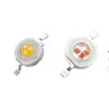 LEDs for flashlights: characteristics, photos, diagrams
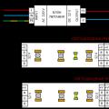 Device and connection diagram of LED RGB strip LED strip rgb 20 meters
 How to make a garage oven from a gas cylinder?