Super powerful DIY TV antenna. DIY TV antenna, simple and quick. Butterfly or antenna made of copper wire
It is not difficult to buy an antenna for a television receiver. An extensive range is offered both in terms of design diversity and signal reception parameters. But in some cases it doesn’t hurt to know how to make the device yourself.
For example, you want to watch TV at your dacha, but there is no corresponding store nearby. Or the existing device receives few channels and the image quality is poor. Self-assembly of the antenna is also useful for educational purposes, when the principle of its operation becomes clear.
A simple option: an antenna made from cans
The simplest antenna that you can make yourself is a design made from tin drinks cans. Such material is available, and production takes no more than 20 minutes if you have the skill. In addition, it gives good results in signal reception, working better than some stationary antennas.
In order to make an antenna from cans, you need to prepare the following components and tools:
- a cable having a length from the TV to the window and slightly longer;
- two tin cans;
- two self-tapping screws;
- plug for inserting the cable into the TV socket;
- insulating tape;
- screwdriver;
- wooden, plastic pin or stick - the basis for attaching cans and cables.
Manufacturing is carried out as follows:
- It is required to fasten the stick and cans at a distance of 7 cm from each other, using insulating tape and a small stick. The cable needs to be stripped from one end so that when the wires (central and side) are separated there is a distance of 7 cm. Then it can be attached to the rings of the cans, if any.
- If the cans do not have rings, screw in screws. At one end we attach the stripped cable wires to the screws. There is a third way - you can solder them. We attach the cord itself, as well as the edges of the cans separated by 7 cm from each other, to the same stick with insulating tape or tape for stability. The free end of the cable must be equipped with a plug.
- The antenna can work in the room. If you need to take it outside the window, we protect it from atmospheric conditions: cover the tin cans with plastic bottles (2-liter containers), cutting off the bottom and neck of them. In the center of the plastic structure we make a hole through which we thread the cable. After connecting, you will need to treat the holes with boiling water to make them sealed.
- The antenna operating in the UHF range is almost ready. You just need to connect it and configure it (turn on auto channel search).

Wire antenna
For the simplest wire antenna, copper or brass wire is used, which does not oxidize too quickly. It is stripped of insulation from both ends. One end will be intended for the TV socket, and the second is attached to the pipe, battery.
You can really pick up a signal with such an antenna, because the pipes go to the roof and amplify the signal. But the number of channels will be no more than 5.
Another case is to stretch the wire to the balcony, for which it must be of sufficient length. Here it can be secured on a clothesline. The image will have better quality than in the previous case, and the number of channels may increase. These are options for manufacturing the most economical antennas.

We use tubes
Antenna parts can consist of a variety of metal profiles, for example, tubes. It is better to use thin-walled materials for the correct flow of high-frequency currents. It also reduces the weight of the structure.
You can make a simple antenna yourself from two identical tubes. It will be able to receive a signal in rural areas at a distance of 30 km from the repeater. The tubes are connected by a cable, the free end of which is connected to the TV.
First you need to find out the broadcast frequency of the TV tower located closest to your home. Based on this, the length of the tubes is selected. The television wave range is 50 - 230 MHz. The entire strip is divided into 12 channels, for each of which the vibrator tube must have its own length.
So for 50 MHz it is 276 cm, and for 223 MHz it is 66 cm. The length of the loop connecting the cable tubes is also proportionally calculated: the lower the frequency, the greater its length.
The following materials and tools are required:
- Two identical pipes with a diameter from 8 to 24 mm: brass, steel - any metal.
- A cable with a resistance of 75 Ohms of the required length (from the TV to the antenna + 2 meters).
- Textolite or getinaks with a thickness of more than 4 mm. Clamps for attaching pipes.
- The rod is the basis for placing the structure.
- Soldering iron, flux, solder, epoxy resin or electrical tape.
Assembly steps
- You need to cut a pipe with a length selected according to the frequency of the television center, and then divide it in half and flatten each part on one side for attachment to the PCB. The distance between the tubes is approximately 7 cm - optimal for good reception. The structure is then securely attached to the holder with clamps.
- The vibrator is installed on the mast and both pipes are connected with a matching device - a cable loop with a resistance parameter of 75 Ohms. The cores are soldered to the tubes, and the braid is connected with a conductor. To do this, you can take a piece of cable and peel off the insulation.
- The central wires from the matching loop and the cable to the TV are also connected, and then their braids using copper wire.
- The TV loop and cable are attached to a rod, which is positioned at the desired height where the adjustment is made. Having caught a good signal, the antenna is fixed. To find out the approximate direction, you can look at the antennas of neighboring houses.
The design of curved tubes is even more effective. But manufacturing such parts is fraught with difficulties.

Improved options
Sometimes an antenna in a country house receives no more than 2 channels. In a short time you can improve the quality of its work. The reason for poor reception is the significant distance of television signal stations. You can use an existing device as a basis.
And also make something new from existing household items:
- You need to take a wire with a diameter of one and a half millimeters, up to 2 meters long, if the antenna is up to 6 meters.
- 1.5 meters of wire twisted in a ring with a diameter of up to 45 cm.
- The second one is also made from wire ring up to 18 cm in diameter.
- The rings are secured by securely fixing them to a piece of plywood, wood or plastic. The antenna is then installed on the roof.
- When setting the location of the rings should be directed towards the signal. To find it, you need to rotate the antenna using an assistant checking the image quality. After setting up the reception, you can use the television system and watch programs.
You can try making a satellite dish from a bucket lid attached to a stick (mast). To do this, you also need a head from an old broken satellite dish, which is attached with wire to a stick.
The cover serves as a reflector, which is attached to the same pin to the wire from the head from below. The head is located towards the reflector, and the second cable extending from it goes to the signal receiver - the TV.
Rules for installing homemade devices
Before you make an antenna yourself, you need to decide on its type. A parabolic design is suitable for satellite reception; making it yourself is not so easy.
Therefore, there are different types of antennas:
- zigzag;
- frame;
- from wave channels;
- vibrators;
- traveling wave catchers;
- as a combination of structures.
The signal receiving circuit or other structure is connected to the television receiver with a cable with a plug at its end. The winding needs to be bent, after which a wire will appear. Both are attached to the plug using screws, if it is equipped with such fasteners.
Or simply insert the central wire into the plug hole, and the winding is also placed inside. The second end of the cable, stripped and twisted into a ring, should be attached to the circuit. For reliability, you need to wrap the attachment point with insulating tape.
When using external structures located on the roof of a house or balcony, it is necessary to adjust the received signal. To do this, the antenna is rotated in different directions until the image is of the best quality. You can look at the neighboring houses for approximate directions.

Signal amplifier
To improve a weak signal, an amplifier is used, which can be purchased. The use of this device is appropriate if the antenna does not quite match the type or the television center is located far away. Then there is quite a lot of noise on the screen, and the image is almost the same.
An amplifier is used only when it is impossible to improve the antenna itself in terms of efficiency. The choice of this part depends on the required parameters, taking into account the distance to the broadcast center.
Antenna amplifier boards are characterized by a gain that allows receiving transmissions at a distance of up to 150 km. When purchasing, you need to indicate the type of antenna, for example, mesh or loop. The device is installed on the antenna using nuts.
It is often necessary to provide the board with a sealed shell that protects it from natural factors: foil or polyethylene. It is best to place an antenna with an isolated amplifier on the roof of the cottage, facing the nearest television tower.
- Before you decide to build an antenna on your own, you need to clarify the operating principle of the specific television receiver for which it is intended. Today, analogue TVs are being replaced by digital ones. An outdoor antenna for a digital receiver does not need to provide a wide band, since only resonance is required at the required parameters.
- Modern broadcasting is mastering UHF frequencies (300-900 MHz) with horizontal polarization. To implement such tasks, a paraboloid antenna with a tuned feed would be suitable. But then you will need direct access to the telecentre tower or tuning to a weather-dependent reflected signal. Consequently, the paraboloid is not always suitable for picking up terrestrial broadcasts, but is appropriate for receiving a satellite signal in the presence of line of sight.
The modern market offers a huge range of antennas for receiving terrestrial television. There are two main types of these products that allow you to receive meter and decimeter radio waves. They can also be divided according to the place of use into outdoor and indoor. Fundamentally, they are not much different. Here, first of all, the emphasis is on size and maintaining the necessary parameters under the influence of weather conditions. In this article we will discuss existing types of these products, consider what parameters they have, and how to conduct testing. And for those who like to tinker, we’ll tell you how to make a decimeter antenna with your own hands.
What's the difference?
Let's try to explain in a nutshell how to determine what type of product is in front of you. The UHF antenna looks like a ladder. Install them parallel to the ground. Meter ones are crossed aluminum tubes. The appearance of both types is shown in the photo below. There are also combined antennas, when both the “ladder” and cross tubes are combined.
Problem of choice
It would seem that everything is simple. However, the buyer is faced with the question of how to choose the right device and what parameters to pay attention to. In general, it is best to test TV antennas directly in the conditions in which they will operate. The passage of a radio signal is often individual for a particular area. Thus, a product shows the same results in laboratory conditions, but completely different results in the field. There are certain tactics that allow you to test both meter and decimeter TV antennas. However, when choosing such a product in a store, we do not have the opportunity to conduct full testing. No seller will agree to give us several different antennas to test. In this case, you have to trust the characteristics of these products. And hope that the selected antenna will perform its functions according to the passport data, and not real conditions.

Main settings
A decimeter antenna is characterized primarily by its radiation pattern. The main parameters of this characteristic are the level of the side (auxiliary) lobes and the width of the main lobe. The width of the diagram is determined in the horizontal and vertical planes at a level of 0.707 from the largest value. So, according to this parameter (the width of the main lobe), diagrams are usually divided into non-directional and directional. What does this mean? If the main lobe has a narrow shape, then the antenna (decimeter) is directional. The next important parameter is noise immunity. This characteristic primarily depends on the level of the back and side lobes of the diagram. It is determined by the ratio of the power released by the antenna, subject to a consistent load at the time of receiving a signal from the main direction, to the power (with the same load) when receiving from the side and rear directions. First of all, the shape of the diagram depends on the number of directors and the design of the antenna.
What does the term “wave channel” mean?
TV antennas of this type are very effective directional receivers of radio signals. They are widely used in areas of clearly weak television airwaves. The antenna (decimeter) of the “wave channel” type has high gain and good directivity. In addition, these products have relatively small dimensions, which (along with the high level of amplification) makes it very popular among residents of holiday villages and other settlements remote from the center. This antenna also has a second name - Uda-Yagi (named after the Japanese inventors who patented this device).

Principle of operation
A decimeter antenna of the “wave channel” type is a set of elements: passive (reflector) and active (vibrator), as well as several directors, which are installed on a common boom. The principle of its operation is as follows. The vibrator has a certain length, it is located in the electromagnetic field of the radio signal and resonates at the frequency of the received signal. In it, an electromagnetic field is induced on each passive element, which also leads to the occurrence of EMF. As a result, they re-emit secondary electromagnetic fields. In turn, these fields induce additional EMF on the vibrator. Therefore, the dimensions of the passive elements, as well as their distances to the active vibrator, are chosen such that the EMF induced by them due to secondary fields is in phase with the main EMF, which is induced in it by the primary electromagnetic field. In this case, all EMFs are summed up, which increases the efficiency of the design compared to a single vibrator. Thus, even an ordinary room can provide stable signal reception.
The reflector (passive element) is installed behind the vibrator 0.15-0.2 λ 0. Its length should exceed the length of the active element by 5-15 percent. Such an antenna produces a one-way directional pattern in the vertical and horizontal planes. As a result, the reception of reflected signals and fields that come from the back of the antenna is significantly reduced. If it is necessary to receive a television signal over long distances, as well as in difficult conditions, in the presence of a lot of interference, it is recommended to use a three or more element antenna, which consists of an active vibrator, one or more directors and a reflector.

Direct and reflected signals
In an article devoted to a wave receiving device (“Tele-Sputnik” No. 11 for 1998), it was noted that in the case when the signal source is not a standard (that is, not a laboratory) generator and emitting antenna, and the signal is broadcast by a television tower, a significant Weather conditions play a role, as does the location where the receiver is installed. This especially affects the operation of UHF products. This is explained by the fact that in the decimeter range there is less, and accordingly, obstacle avoidance is much worse, and any signal reflections play an important role in the quality of the received picture. In particular, even the wall of a house can be a wave reflector. So, in conditions where there is no direct visibility, this property can be used - to receive the reflected signal. However, its quality will be lower than that of the direct one. If the level of the transmitted signal is high, but there is no line of sight, then you can use the reflected wave. In fact, an indoor decimeter antenna works precisely on this principle. After all, it is difficult to catch a direct wave in a room if the windows face the opposite direction. Therefore, if you try, you can always find a point where the received signal will be higher. But in the case of direct visibility, any reflected interference will spoil the received picture.
A technique that allows you to compare antenna parameters
In order to test receiving devices, they need to create the same conditions:
1. Select the installation location where your antenna will operate. You can use a balcony, roof or mast. The main thing is that both the height and the location are the same for all products.
2. The direction to the source of the broadcast signal should be maintained with an accuracy of three degrees. To do this, you can make a special mark on the mounting pipe.
3. Measurements should be carried out under the same weather conditions.
4. The cable connecting the antenna and the TV must have the same resistance and length. It is best to use one wire, changing only the receivers.
Testing should only be carried out on products of one type. For example, an indoor UHF antenna should not be compared with an outdoor one or with meter receivers. It should be understood that field tests may produce results that differ significantly from laboratory tests.

UHF antenna for digital television
Recently, the media have been increasingly talking about the need to switch to digital television. Many have already done this, and some are still thinking about it. So far, the signal is broadcast in both modes. However, the quality leaves much to be desired. In this regard, people are interested in what decimeter antennas can be used for T2. Let's look at this issue. Essentially, digital television broadcasts on a UHF channel. So a standard UHF antenna may be suitable for receiving it. You can often see receivers in stores that indicate that they are intended for digital television. However, this is a marketing ploy that allows you to sell a standard decimeter antenna for more than it costs. When purchasing such a product, you will not have a guarantee that it will provide better reception than what you already have in your home and has been working for more than one year. As we said earlier, the quality depends mainly on the level of the broadcast signal and line of sight conditions. However, it should be borne in mind that in most cities, significantly more powerful generators are used for transmitting digital television than for analogue. This is done in order to speed up the transition to the new standard. After all, viewers want to see a clear image, and not “snow” on the screens. Therefore, if there is a receiver in the window that says “UHF antenna for DVB T2”, know: this does not mean that this is some kind of special product. It’s just that a not entirely honest seller wants to profit from an uninformed buyer. You should also know that the transition program to the new standard provides for the creation of advisory centers. In them you can get comprehensive information on any issue related to digital television. All consultations are provided free of charge. In some cities, this equipment is in test mode, so the signal may be unstable or weakened. Don’t worry, the center staff will always tell you how to solve the problem with signal reception quality.

DIY decimeter antenna
The length of UHF waves falls within the range from 10 cm to 1 m. Their name comes from this feature. At this frequency they propagate predominantly in a straight line. They practically do not bend around obstacles and are only partially reflected by the troposphere. In this regard, long-distance communication in the UHF range is very difficult. Its radius does not exceed one hundred kilometers. Let's look at a couple of examples of how to make a decimeter antenna at home.
The first version of a homemade television broadcast receiver will, so to speak, be assembled on the knee from scrap materials. UHF channels are located in the range from 300 MHz to 3 GHz. Our task is to produce an antenna that will operate precisely at these frequencies. For this we need two 0.5 liter beer cans. If you use a larger capacity, the received frequency will decrease. For installation you will need some kind of frame; you can use a board 10 cm wide. You can also use a regular wooden hanger, in which case the resulting antenna can be hung on a nail in any convenient place in the room. In addition to the frame and cans, you need to prepare a pair of self-tapping screws, tools, a coaxial cable, a connector, terminals, and insulating tape. We put a television connector on one end of the cable and solder it. We insert the second end into the terminal block. Next, we attach the terminals to the necks of the cans with screws. The wires should fit snugly to the metal. Now let's start assembling the antenna itself. To do this, we secure the jars on a horizontal crossbar with their necks facing towards each other. The distance between them should be 75 mm. You can use insulating tape to secure the cans. That's it, the antenna is ready! Now we need to find a place for stable reception of a television signal and hang our “hanger” in this place.

Receiver for digital television
This section is intended for people who do not want to use a regular (analog) product, but want a special UHF antenna to be used for the new format. It is also easy to assemble such a receiving device with your own hands. To do this, we will need a square wooden (or plexiglass) frame with a diagonal of 200 mm and a regular RK-75 cable. The option presented to your attention is a zigzag antenna. It has proven itself to be excellent when working in the digital television reception range. Moreover, it can be used in places where there is no direct visibility to the signal source. If your broadcast is weak, you can connect an amplifier to it. So let's get to work. We strip the end of the cable by 20 mm. Next, we bend the wire into a square shape with a diagonal of 175 mm. We bend the end outward at an angle of 45 degrees, and bend the second stripped end to it. We connect the screens tightly. The stripped central core hangs freely in the air. On the opposite corner of the square, carefully remove the insulation and screen over a 200 mm area. This will be the top of our antenna. Now we connect the resulting square with a wooden frame. At the bottom, where the two ends are connected, copper staples made from thick wire should be used. This will ensure better electrical contact. That's all, the decimeter antenna for digital television is ready. If it will be installed outside, you can make a plastic case for it, which will protect the device from precipitation.
Digital television is broadcast in the UHF range. Therefore, you can use almost any UHF antenna. But I needed simple, easily repeatable and strong UHF antenna range.
Such that you could carry it with you, and on occasion you wouldn’t mind giving it to people for a small amount.
The basis was taken from the famous “ eight“, with the difference that I used it without a reflector.
The material for the antenna sheet can be any conductive material of suitable cross-section. It can be copper or aluminum wire with a thickness of 1 to 5 mm, a tube, strip, busbar, corner, profile... I took copper wire with a diameter of 3 mm. Easy to solder, easy to bend during assembly, easy to straighten if bent.
The outer side of the square is 14 cm, the inner side is slightly smaller - 13 cm due to the fact that the middle of the two squares does not converge, about 2 cm from corner to corner.
So, if you are not making an antenna from wire, then measure it this way - the top sides are 14 cm, the sides are 13.
All sizes are approximate. Don't be afraid to get shortchanged or make mistakes. Our plans do not include making an antenna that meets all standards. We need a simple but workhorse. A surrogate, but reliable. Surrogate because:
1
. Personally, I definitely couldn’t keep the sizes.
2
. There is no reflector.
3
. I took a 50 ohm cable instead of 75 ohm, but with a thick braid. Friends usually used this cable for car antennas for 27 MHz radio stations.
Nevertheless, the antenna works quite well.
A digital signal has a peculiarity; it either exists or it doesn’t. When receiving analog television, different channels were shown with different levels of interference, and when removed, the level of snow on the screen simply increased until the signal disappeared completely. In digital, the signal is almost the same on all channels, and if there is reception, then there is all channels.
I have tested this antenna on more than a dozen TVs in our region.
So. We measure a piece with a total length of 112 cm and bend the wire. The first section is 13 cm + 1 cm for the loop (for strength). The second and third are 14 cm each, the fourth and heels are 13 cm each, the sixth and seventh are 14 cm each, and the last eighth is 13 cm + 1 cm stiffening loop.
We strip 1.5 - 2 cm at both ends, twist the two loops behind each other, and then solder the joint. This will be one cable connection pin. After 2 cm another. It doesn’t matter where to solder the central core or the braid.

Solder spacing 2 cm
I took about three meters of cable. In most cases, it’s enough if you don’t do it for yourself personally. For yourself, measure out as much as you need.
I stripped the cable from the antenna side by two centimeters, to the plug - 1 cm. If the plug is like in the photo. You can take any, stronger.

Stripping the cable
The plug was cleaned with a file and a scalpel.

After sealing, both soldering points are filled with glue from a gun. On the plug, first hot glue is poured into the soldering area and into the plastic cap, with a reserve; the excess can then be removed. Then, before the glue cools down, everything quickly comes together. You can’t gnaw such a joint with your teeth. Reliable, at the same time elastic.
The soldering on the antenna itself is also filled with glue, but for the rigidity of the structure, a frame is taken - any lid, box, .... I took the cap from a 20-liter water bottle, of which I had accumulated a sufficient amount. If you are making an antenna like me for mass production, then it is better to immediately use common materials that are literally lying under your feet for better repeatability of the antenna. If the antenna is made in a single copy for quick riveting, then you don’t have to fill anything at all.

The result is such a design that can be stuck anywhere - on a cornice, on a curtain, on a window frame. To do this, you can carry with you a piece of wire, a couple of screws, a couple of pins...

Antenna assembly
If the antenna is dented during transfer, it can be easily and without damage aligned. This is perhaps its main advantage.
I don’t always carry this design with me, but only when I receive a specific order to connect a DVB-T2 digital television tuner. It fits easily with the tool in my backpack.
It is more convenient to make several antennas at once. Takes less time.
This is how my friend fixed the antenna, using it as an outdoor one. The tower is about 9 km away. Reception is reliable despite the simplicity of the antenna.

Despite the constant development of television broadcasting (transition to digital format, the possibility of installing satellite or cable television, Internet TV), the use of antennas still remains relevant. This is especially true in suburbs and rural areas. Sometimes the TV antenna breaks down, and there is no place nearby where you can buy it. Therefore, information on exactly how you can make an antenna for a TV with your own hands may be useful.
An antenna is a device that can receive or transmit radio waves. Types of over-the-air television antennas (that is, those that receive signals from towers or repeaters) can be divided by location into:
- External;
- Indoor.
It makes sense to use indoor antennas for a TV only if there is a good signal, but in the country or away from TV repeaters they use external ones. In addition to location, TV signal receivers are divided into:
- Passive - they receive a signal only due to their shape;
- Active - the signal passes through the converters.
The quality of the signal from a passive TV antenna will directly depend on its size - the larger it is, the better.

The advantages include:
- Ease of manufacture;
- Low cost: can be made from scrap materials;
- No separate power required.
However, the disadvantages are quite significant:
- Interference Immunity: It is very important to choose a location for a good signal;
- Requires a greater height for installation, additional reinforcements must be used;
- Bulky, not suitable for home installation due to their size, mainly used for outdoor installation.
Active antennas additionally use various decoders and amplifiers, which make the signal more powerful. Therefore, their advantages are as follows:
- Can be used anywhere, even with low signal levels;
- Can be of different sizes and shapes;
- You can adjust the level of gain and noise reduction;
- Low influence on signal quality from terrain, weather, and various buildings.
The disadvantages include:
- Complex device;
- Need a power source;
- Higher cost;
- Less reliable due to the presence of electronics.


Radio waves that are transmitted over the air (wave transmission medium) have a certain size and frequency. The television channel is in the range of meter and decimeter frequencies:
- Meter waves (MV) have a length from 1 to 10 m and a frequency from 30 to 300 MHz;
- Decimeter waves (UHF) have a length from 0.1 to 1 m and a frequency from 300 to 3000 MHz.
Based on the frequencies of received signals, television antennas can be divided into the following types:
- All-wave. They are capable of receiving both analog and digital signals, but the reception distance is short.
- Log-periodic. Can receive waves in the meter and decimeter range.
- Decimeter. Designed for short waves only.
All-wave, otherwise called frequency-independent, receiving devices are extremely simple in design, so you can make them yourself. The most famous of them: “butterfly”, made from beer cans, from two petals. Most often they are used at a short distance from the repeater and with a low level of interference.
Log-periodic receiving devices consist of a main rod and transverse bars of increasing length. It is much more difficult to manufacture than the previous ones. Correct design requires knowledge of all frequencies used, as well as orientation to the repeater. But if the design calculations are done correctly, the antenna will transmit the signal very well.

Decimeter ones can have both very simple and very complex designs. The most famous: “eight”, ring, frame.
Most channels, including digital ones, are broadcast in the UHF range. The design of such repeaters is simpler. But rounding obstacles with waves of this length is worse, and reflections and distortions play a strong role in the quality of the signal.
Based on these features, you need to figure out how TV antennas can be made on your own.

In addition to typing by wave reception, location, as well as the presence of electronic elements, television antennas also differ in all possible design implementations: wave channel, traveling wave, zigzag, frame, etc.
Assembly principle
In order for a made TV antenna to work properly, you need to adhere to some principles.
First you need to decide where the structure will be used: in a garage, in a country house, in a house, in an apartment, etc. Based on this, choose the type of receiving device and what the antenna can be assembled from.
The main elements that may be needed are a television cable, metal strips, wires, insulating materials, adhesive tape, a soldering iron, and self-tapping screws.

It is better to connect the elements of the receiving device, especially through which the useful signal will pass, by soldering> yo
The best signal reception will be if the distance from the TV tower to the receiver is not blocked by buildings, trees and other obstacles. In this case, in order to catch the signal, a simple wire will be enough. And an indoor TV antenna in such a situation will be very easy to manufacture and will not require an amplifier.
Outdoor antennas can be similar in design to indoor antennas, but must be made of more durable materials that can withstand weather conditions. Should be placed directly near windows or on the roof.

If the signal is too weak, an amplifier may be required.
So, how to make a television antenna with your own hands:
- The device should be made carefully and with the least possible connections to reduce signal loss;
- The television antenna must be positioned along the axis of the electromagnetic wave for the best capture of its constituent elements;
- Must be protected from interference;
- It is important to know the television broadcast frequency, which will determine the size of the receiving device.
DIY antenna options
A simple TV antenna can be made from materials that are usually found in any home.
For example, you can even make a satellite dish yourself from foil, a metal can, an umbrella and a wire.
Using foil you can make the following receiver:
- The foil is leveled and glued at the bottom of the box.
- From 2 pieces of television cable you need to remove 2.5 cm of insulation.
- Twist the cable braid into a separate contact.
- Make a figure eight from the pieces of cable, while the contacts should not be fastened in the middle and should be spaced 1 cm apart.
- Place the cable on the outside of the box (without foil).
- Another cable is taken that will connect the antenna to the receiver.
- Its end is stripped, the braid is also twisted separately.
- 3 central cores and 3 cable braids are connected in one place.
- We place the TV antenna in the place of best reception.

Let's consider simple and popular options for TV antennas: from beer cans, coaxial cable and zigzag.
From coaxial cable
This is the most basic version of a cable TV antenna for receiving a digital or analog signal. You can complete this design yourself within half an hour.
Coaxial cable is an electrical wire for transmitting radio frequency signals. Comprises:
- Outer shell;
- An external conductor, otherwise called a screen or braid;
- Insulation that separates the central core from the braid;
- Internal conductor (central core).
Such a cable can have a resistance of 50 or 75 Ohms. To make homemade antennas, it is recommended to use 75 ohms.

You will need a piece of cable at least 0.5 meters long. On one side, remove the top insulation and the insulation of the central core by 5 cm. The core with braid should be twisted. Now you need to step back 20-22 cm from this end and remove everything until the insulation of the central core. The length of this section will be about 2 cm. Next, the same distance is measured as it was before this section, that is, 20-22 cm. From a section of 1 cm, only the top insulation is removed. Now a loop is made: the bare end is screwed to the gap without external insulation.

It is better to wrap bare areas with electrical tape, especially if the antenna will be used outdoors>e
The device must be directed towards the tower.
You can make an antenna from copper wire.
To do this, the ends are stripped of insulation. One end is attached to the TV, and the other to the heating pipe, which will act as an amplifier. Such a wire antenna will be able to receive about 5 channels.
It is possible to make a receiving loop device from wire to receive a digital signal. To do this you will need to calculate the length of the loop. You need to know the average frequency of the signal. And 300 divided by this frequency. The resulting value will be the length of the loop. A piece of wire is closed into a ring, and a cable is soldered to the ends. Coax can be used instead of wire. Then the ring antenna will be similar to the option described above.

Despite the simplicity of the design, this method, with correct calculations, reduces interference and reliably receives the signal.
To improve the signal, you can try boosting the antenna.
Let's consider options for how to strengthen a TV antenna with your own hands:
- Place the receiving device as close to the window as possible, eliminating obstacles;
- Adjust position;
- You can extend the antenna with a piece of wire;
- Add a signal amplifier to the design;
- Place external ones as high as possible.
From beer cans
The easiest way to replace a broken TV antenna is to create one out of beer cans.
Let's look at the method of making a simple antenna for digital TV, made from improvised means, namely from metal cans.
You will need the following materials:
- Beer cans with a smooth surface (pre-wash and dry), in the simplest version – 2 pieces;
- Self-tapping screws;
- A piece of television cable;
- Plug;
- Electrical tape or tape;
- A stick made of a material that does not conduct electricity (you can use a trempel).
The stages of work are as follows:
- The cable must be of such a size that it is sufficient for the height at which you plan to hang the antenna. If there is no plug on a piece of cable, it is stripped from one side of the winding and a plug is placed on it.
- The second end is also cleared of the winding. Inside there is a central core and a braid (screen).
- Holes are made in the jars on equal sides. It doesn't matter if it's the top or bottom of the jar.
- The central core is attached to one can using a self-tapping screw, and the braid to the other. In this case, you need to make a loop that will wrap around the self-tapping screw. And when screwing in, he should clamp it well with his cap.
- Instead of screws, you can solder contacts.
- You need to attach the cans to the stick so that they are on the same axis. The distance between the banks is usually taken from 7 to 10 cm.
- When the optimal distance is selected, the cans are securely fixed with adhesive tape.

It is better to first secure the cans with an elastic band so that it is convenient to adjust the distance
When you have made such an antenna with your own hands, when using it outdoors, it is advisable to build a protective cap, for example, from a plastic bottle. If moisture gets in, the contacts will oxidize and the signal will deteriorate. The street version can be improved by adding several sections with banks.
Zigzag
This TV antenna is also called the “eight” or Kharchenko antenna. Shows one of the best signal reception among devices that you can make yourself. Its diagram looks like:

Dvb t2 is the newest digital television broadcast format. The digital format has many advantages over analogue: greater resistance to interference, the signal will be more widely available, and its quality will be better. The digital format requires smaller antennas and lower transmitting power.
Making an antenna for dvb t2 reception is quite simple. It should be noted that digital TV is transmitted to the UHF.
Now let's look at how you can make an antenna for digital TV with your own hands:
You need any material that conducts electric current. This could be a tube, wire, corner, etc. The easiest way is to use wire made of aluminum, brass or copper (these 2 options are better), with a thickness of 2 to 5 mm. You will need to make 2 diamonds from the material, as in the figure. You can also use welding electrodes, each of which will be a side of a rhombus.
Dimensions available for this pattern:
– B1=14 cm;
– B2=13 cm;
– angles are preferably about 90 0.
The outer sides should be slightly longer. This is done so that the diamonds in the middle do not connect.
But these parameters are more suitable for home use. More often you can find a recommendation to take the side of the rhombus 45 cm.

You can independently calculate the dimensions of the antenna for digital TV. To do this, you need to know the wavelength of the signal broadcast and divide by 4. These will be the sides of the rhombuses
There are also calculators for calculating the parameters of “bi-square” antennas, which can be found in Internet resources.
When measuring the length of the wire, you need to take a margin of 1-2 cm for the loop that will close the loop. You can simply twist or solder the remaining end.
After this, a coaxial cable is taken and stripped. The contacts will need to be soldered to the central corners of the diamond, which do not meet. The central core is soldered to one corner, and the braid to the other. The central part can be placed in a plastic case and filled with glue for reliability.
To reduce third-party interference, you can install a screen behind the receiver. It can be simply foil stretched over plywood or a lattice made of metal tubes or wire. The screen should be located on the opposite side of the tower and not in contact with the antenna.
If the antenna will be used outside, you can assemble it with an amplifier. The amplifier can be a simple board that is attached to the antenna antenna or a larger device that requires power from the network.

In the case of an amplifier, the “figure eight” is attached to the plate, and the wire can be flattened at the attachment point, and the amplifier can be immediately attached to the central part.
You can improve the figure eight design by adding more rhombuses symmetrically.
Let's look at a few more complex TV antenna devices.
Double and triple square
This option is a narrowband TV antenna, that is, you can receive only a few channels, but with high-quality transmission. It can be used to receive a weak signal or if the signal is being overwhelmed by other, more powerful signals. But precise orientation to the source of television waves is important.

For manufacturing you will need tubes or wire. To obtain up to 5 channels in the meter range, the thickness should be 10-20 mm. For larger quantities – 8-15 mm. For UHF it is only 3-6 mm.
In a double square, 2 squares are made from the material, with one slightly larger than the other. The smaller one is called a vibrator, and the larger one is called a reflector. A vibrator is present in every antenna and is a system for producing vibrations.
The frames are attached parallel to each other. They are secured at the top and bottom centers with the help of arrows, which, in turn, are attached to a vertical support. The lower boom must be made of non-conductive material. The centers of both frames should be on the same line and directed towards the TV transmitter. In a three-frame design, an even smaller square is added.
Another design for the UHF - frame.

1. Do-it-yourself UHF television antenna
1.
Ring-coaxial cable RK75, 530 mm long.
2.
Loop-coaxial cable RK75, 175 mm long.
3.
To the antenna.
Assembly:
To assemble this antenna, you don’t even have to go shopping.
To do this, you need to take an RK75 antenna cable 530 mm long (for the ring) and 175 mm long. (for loop).
Connect as shown in the figure.
Secure it to a sheet of plywood (plexiglass) using wire clamps.
Direct to telecentre.
Here is a UHF antenna that will work no worse than a purchased one.
2. Do-it-yourself UHF television antenna “Narodnaya”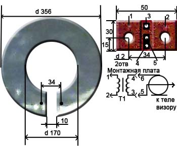
The antenna is an aluminum disk with an outer diameter of 356mm and an inner diameter of 170mm. and 1mm thick, in which a 10mm wide cut was made.
A printed circuit board made of glass lite 1mm thick is installed in place of the cut. This board has two holes for mounting with M3 screws.
The leads of the matching transformer T1 are soldered to the printed circuit board attached to the antenna.
For a transformer, it is best to use a ring core with an outer diameter of 6...10mm and an inner diameter of 3...7mm. and thickness 2...3mm.
The transformer windings are covered with a single-layer insulated wire with a diameter of 0.2...0.25 mm. and have the same number of turns, from 2 to 3 turns. The length of the coil bends is 20mm.
With such a transformer, reception in the meter and decimeter range is possible at a distance of 25...30 km. At a distance of up to 50 km. The antenna works satisfactorily only on decimeter channels.
Without a transformer, the distance of reliable reception is halved.
However, there is a circuit that allows you to get similar results without a transformer; for this you need to assemble the following circuit: 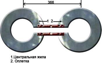
3. Do-it-yourself log-periodic television antenna (UHF).
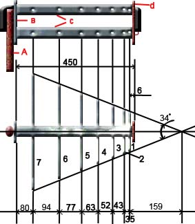

A. Mast
IN. Metal plate (dimensions 87x30x5)
WITH. metal tubes d 16…19mm
D. textolite plate (dimensions 87x30x5)
E. braid
F. coaxial cable
G. central core
7,6,5,4,3,2,1. vibrators
Assembly
1. Take two metal tubes 450 mm long and 16...19 mm in diameter.
2. Make two plates measuring 87x30x5mm. (one is made of metal, the other is made of textolite), drill holes in them, as shown in the pictures.
3. Secure the tubes in the plates (to the metal plate by soldering, and to the textolite plate using screws screwed from the ends of the plate with a diameter of 2.5 mm.
4. In metal tubes, along their length, at the distances indicated in the figure, drill holes with a diameter of 3.3 mm. and cut the M4 thread.
5. Screw 14 directors made from a rod with a diameter of 5 mm into the holes. At one end of each rod, cut an M4 thread to a length of 10mm.
The lengths of the directors, taking into account the part of the length of the threaded end, according to the vibrator number (see figure), are given in the table:
Vibrator No.…..length in mm…..number of pieces
1…………………………..107………………..2
2…………………………..129………………..2
3…………………………..155………………..2
4…………………………..186………………..2
5…………………………..225………………..2
6…………………………..272………………..2
7…………………………..330………………..2
6. Place the coaxial cable in one of the tubes and solder it according to the figure. Paint the solder ends with paint.
7. Attach the antenna to the mast.
Antenna from user Evgen:
1. Take two EMPTY jars - for channels 21 to 41, 0.5 l is better, for channels 42 - 69 - 0.33 l.
2. Fasten them in any convenient way (electrical tape, adhesive tape, rope, glue, etc.) on a solid piece of dielectric (rail, stick, piece of plywood - it is better to paint or varnish the wood, textolite, getinax, etc.) onto at a distance of 10 - 15 mm from each other.
3. We make 2.5 - 4 mm holes in each jar along the edges (as many screws, washers, nuts can be found) and with the help of these we attach the central core of the cable to one jar, and the braid to the other. You can attach any balancing device, but you can do without it.
The receiving distance depends on the installation location of this design (outside is better) and the power of the transmitter.
The holes are on those edges where the jars are closer to each other. And it’s more convenient to first fasten the cable (and the balancing device - if you’re lazy), and then the jars to the supporting structure.
 DIY brick foundation: strip and columnar
 How to lay parquet: methods, necessary tools and step-by-step process for proper installation
 How to lay parquet: methods, necessary tools and step-by-step process for proper installation