Homemade coil for a pulse metal detector. Twisted pair coil for metal detector DIY ring coil for metal detector
There is no need to explain to anyone what a metal detector is. This device is expensive, and some models are quite decent.
However, you can make a metal detector with your own hands at home. Moreover, you can not only save thousands of rubles on its purchase, but also enrich yourself by finding a treasure. Let's talk about the device itself and try to figure out what is in it and how.
Step-by-step instructions for assembling a simple metal detector
In this detailed instruction, we will show you how you can assemble the simplest metal detector with your own hands using available tools. We will need: an ordinary plastic box for a CD, a portable AM or AM / FM radio, a calculator, a VELCRO contact tape (Velcro). So let's get started!
Step 1. Disassemble the case of the CD box... Carefully disassemble the plastic case of the CD, removing the insert that holds the CD in place.
STEP 1. Removing the plastic insert from the sitboxStep 2. Cut 2 strips of Velcro... Measure out the area in the center of the back of your radio. Then cut 2 pieces of Velcro to the same size.
 STEP 2.1. We measure approximately in the middle of the area on the back of the radio (highlighted in red)
  STEP 2.2. Cut out 2 Velcro straps of the appropriate size as measured in step 2.1
 Step 3. Secure the radio. With the sticky side, attach one Velcro to the back of the radio and the other to one of the inner sides of the CD case. Then attach the radio to the plastic case of the CD with Velcro and Velcro.


Step 4. Secure the calculator... Repeat steps 2 and 3 with the calculator, but apply the Velcro on the other side of the CD case. Then secure the calculator to this side of the box using the standard Velcro-to-Velcro method.

Step 5. Tuning the radio range... Turn on the radio and make sure it is tuned to the AM band. Now tune it to the end of the AM band, but not the radio station itself. Turn up the volume. You should only hear one noise.

Prompt:
If you have a radio station that is at the very end of the AM range, try to get as close to it as possible. In this case, you should only hear one noise!
Step 6. Roll up the CD box. Turn on the calculator. Begin to roll the side of the calculator box towards the radio until you hear a loud beep. This beep signals to us that the radio has picked up an electromagnetic wave from the calculator's circuitry.
 STEP 6. Turn the sides of the CD box towards each other until a characteristic loud signal is heard
 Step 7. Bring the assembled device close to a metal object. Open the flaps of the plastic box again so that the sound we heard in step 6 is barely audible. Then start moving the box with your radio and calculator close to the metal object and you will hear a loud sound again. This indicates the correct operation of our simplest metal detector.

Instructions for assembling a sensitive metal detector based on a dual-circuit oscillator circuit
Operating principle:
In this project, we will build a metal detector based on a double oscillator circuit. One oscillator is fixed, while the other varies depending on the proximity of metal objects. The beat frequency between these two oscillator frequencies is in the audio range. At the moment the detector passes over a metal object, you will hear a change in this beat frequency. Different types of metals will cause a positive or negative shift by raising or lowering the audio frequency.
We need materials and electrical components:
| Copper multilayer PCB, single sided 114.3 mm x 155.6 mm | 1 PC. |
| Resistor 0.125W | 1 PC. |
| Capacitor, 0.1μF | 5 pieces. |
| Capacitor, 0.01μF | 5 pieces. |
| Capacitor electrolytic 220μF | 2 pcs. |
| PEL type winding wire (26 AWG or 0.4 mm in diameter) | 1 unit |
| Audio jack, 1/8 ', mono, panel mount, optional | 1 PC. |
| Headphones, 1/8 'plug, mono or stereo | 1 PC. |
| Battery, 9 V | 1 PC. |
| Connector for binding 9V battery | 1 PC. |
| Potentiometer, 5 kOhm, audio taper, optional | 1 PC. |
| Switch, single-pole changeover | 1 PC. |
| Transistor, NPN, 2N3904 | 6 pcs. |
| Sensor wire (22 AWG or 0.3250 mm 2) | 1 unit |
| Wired speaker 4 ' | 1 PC. |
| Speaker, small 8 ohm | 1 PC. |
| Locknut, brass, 1/2 ′ | 1 PC. |
| Threaded PVC pipe connector (1/2 'hole) | 1 PC. |
| 1/4 ′ wooden dowel | 1 PC. |
| 3/4 'wooden dowel | 1 PC. |
| 1/2 'wooden dowel | 1 PC. |
| Epoxy resin | 1 PC. |
| 1/4 ′ plywood | 1 PC. |
| Wood glue | 1 PC. |
We need tools:
So let's get started!
Step 1: Make a pcb... To do this, download the board design. Then print it and etch it on the copper board using the toner-to-board method. With the toner transfer method, you print a mirror image of the board design using a conventional laser printer, and then transfer the design onto the copper cladding with an iron. During the etching phase, the toner acts as a mask keeping the copper tracks while like the rest copper dissolves in chemical bath.

Step 2: Fill the board with transistors and electrolytic capacitors ... Start by soldering 6 NPN transistors. Pay attention to the orientation of the collector pins, emitter pins, and transistor base. The base leg (B) is almost always in the middle. Next we add two 220μF electrolytic capacitors.


 Step 2.2. Add 2 electrolytic capacitors
 Step 3: Fill the board with polyester capacitors and resistors. Now we need to add 5 0.1μF polyester capacitors in the locations shown below. Then add 5 0.01μF capacitors. These capacitors are non-polarized and can be soldered to the board with feet in any direction. Next, add 6 10k resistors (brown, black, orange, gold).

 Step 3.2. Add 5 0.01μF capacitors
  Step 3.3. Add 6 resistors 10 kOhm
 Step 4: We continue to fill the electrical board with elements. Now you need to add one 2.2 mΩ resistor (red, red, green, gold) and two 39 kΩ (orange, white, orange, gold). And then solder the last 1K resistor (brown, black, red, gold). Next, add pairs of wires for power (red / black), audio output (green / green), reference coil (black / black), and detector-coil (yellow / yellow).
 Step 4.1. Add 3 resistors (one for 2 mΩ and two for 39 kΩ)
  Step 4.2. Add 1 resistor of 1 kOhm (far right)
  Step 4.3. Add wires
 Step 5: We wind the turns on the coil. The next step is winding the turns on 2 coils, which are part of the LC generator circuit. The first is the reference coil. I used a 0.4mm diameter wire for this. Cut off a piece of the dowel (about 13 mm in diameter and 50 mm in length).
Drill three holes in the dowel to pass through them with wires: one longitudinally through the middle of the dowel, and two perpendicularly at each end.
Slowly and carefully wrap as many turns of wire as you can around the dowel in one layer. Leave 3-4 mm of bare wood at each end. Resist the temptation to "twist" the wire — this is the most intuitive way to wind it, but it’s not the right way. You must rotate the dowel and pull the wire with you. Thus, he will wind the wire around himself.
Pull each end of the wire through the perpendicular holes in the wall plug and then one through the slotted hole. Secure the wire with tape once you're done. Finally, use sandpaper to remove the coating on the two open ends of the spool.


Step 6: We make a receiving (search) coil. It is necessary to cut the spool holder from 6-7 mm plywood. Using the same 0.4mm diameter wire, wind 10 turns around the groove. My coil is 152mm in diameter. Using a 6-7mm wooden peg, attach the handle to the holder. Do not use a metal bolt (or something similar) for this - otherwise the metal detector will constantly find you treasure. Again, using sandpaper, remove the coating from the ends of the wire.
 Step 6.1. Cut out the spool holder
  Step 6.2 We wind 10 turns around the groove with a wire of 0.4 mm in diameter
Step 7: Setting up the reference coil. Now we need to tune the frequency of the reference coil in our circuit to 100 kHz. For this I used an oscilloscope. You can also use a multimeter with a frequency counter for these purposes. Start by connecting the coil to the circuit. Then turn on the power. Connect a probe from an oscilloscope or multimeter to both ends of the coil and measure its frequency. It should be less than 100 kHz. You can, if necessary, shorten the coil - this will reduce its inductance and increase the frequency. Then new and new dimensions. Once I got below 100 kHz, my coil was 31mm long.


Metal detector on a transformer with W-shaped plates

The simplest metal detector circuit. We need: a transformer with W-shaped plates, a 4.5 V battery, a resistor, a transistor, a capacitor, and headphones. Leave only the W-shaped plates in the transformer. Wind 1000 turns of the first winding, and after the first 500 turns, tap off with a PEL-0.1 wire. Wrap the second winding 200 turns with PEL-0.2 wire.
Attach the transformer to the end of the boom. Seal it against water ingress. Turn it on and bring it closer to the ground. Since the magnetic circuit is not closed, when approaching the metal, the parameters of our circuit will change, and the tone of the signal in the headphones will change.

An uncomplicated scheme using common elements. You need transistors of the K315B or K3102 series, resistors, capacitors, headphones, a battery. The denominations are shown in the diagram.
Video: How to make a metal detector (metal detector) with your own hands
A master oscillator with a frequency of 100 Hz is assembled on the first transistor, and a search oscillator with the same frequency is assembled on the second. As a search coil, I took an old plastic bucket with a diameter of 250 mm, cut it off and wound a copper wire with a cross section of 0.4 mm2 in the amount of 50 turns. I put the assembled circuit in a small box, sealed it and fixed everything on the bar with adhesive tape.
A circuit with two generators of the same frequency. There is no signal in standby mode. If a metal object appears in the field of the coil, then the frequency of one of the generators changes and a sound appears in the headphones. The device is quite versatile and has good sensitivity.

An uncomplicated scheme based on simple elements. You need a microcircuit, capacitors, resistors, headphones, a power supply. It is advisable to first assemble the L2 coil, as shown in the photo:

A master oscillator with a coil L1 is assembled on one element of the microcircuit, and the coil L2 is used in the search oscillator circuit. When metal objects enter the sensitivity zone, the frequency of the search loop changes and the sound in the headphones changes. With the handle of the capacitor C6, you can adjust the excess noise. A 9V battery is used as a battery.
In conclusion, I can say that everyone who is familiar with the basics of electrical engineering and who has enough patience can assemble the device to bring the job started to the end.
Principle of operation
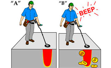
So, a metal detector is an electronic device with a primary sensor and a secondary device. The role of the primary sensor is performed, as a rule, by a coil with a wound wire. The operation of a metal detector is based on the principle of changing the electromagnetic field of the sensor with any metal object.
The electromagnetic field created by the metal detector's sensor induces eddy currents in such objects. These currents cause their own electromagnetic field, which changes the field created by our device. The secondary device of the metal detector registers these signals and signals to us that a metal object has been found.
The simplest metal detectors change the sound of the signaling device when the desired object is found. More modern and expensive samples are equipped with a microprocessor and an LCD display. The most advanced firms equip their models with two sensors, which allows them to search more efficiently.
Metal detectors can be roughly divided into several categories:
- public devices;
- middle class devices;
- devices for professionals.
The first category includes the cheapest models with a minimum set of functions, but their price is very attractive. The most popular brands in Russia: IMPERIAL - 500A, FISHER 1212-X, CLASSIC I SL. Devices in this segment use an ultra-low frequency "receiver-transmitter" scheme and require constant movement of the search probe.
The second category, these are more expensive units, have several replaceable sensors and several control knobs. They can work in different modes. The most common models: FISHER 1225-X, FISHER 1235-X, GOLDEN SABER II, CLASSIC III SL.
 Photo: general view of a typical metal detector
 All other devices should be classified as professional. They are equipped with a microprocessor and can operate in dynamic and static modes. They allow you to determine the composition of the metal (object) and the depth of its occurrence. The settings can be automatic, or you can adjust them manually.
To assemble a homemade metal detector, you need to prepare several items in advance: a sensor (a coil with a wound wire), a holder rod, an electronic control unit. The sensitivity of our device depends on its quality and size. The rod-holder is selected according to the person's height so that it is convenient to work. All structural elements are fixed on it.
The dream of finding a treasure is increasingly being replaced in our time by a more realistic program for searching for precious metals in a natural or artificial environment.
In modern conditions, it is very important to find and extract valuable materials found among the waste, or in another uncontrolled environment.
Hardware is an important component of this search technology.
Search and recovery of gold and valuable metals from waste, garbage, in the natural environment is part of the recycling strategy, technology for the effective processing of used materials, including.
Searching for them in the ground or in the mass of industrial and other wastes not only requires the use of equipment, but also stimulates its improvement. Are being created devices of different levels and specializations... There is an interest in such equipment among amateurs and enthusiasts of searching for valuable metals.
 The metal detector is the most important tool for manual metal search in a chaotic natural or artificial environment.
With the help of such a device, you can search not only, but also, silver and other precious metals.
The principle of the device any metal detector based on electromagnetic effects.
This is how a typical metal search technology works:
- Appliance creates an electromagnetic field.
- Metal an object, hidden in a foreign environment, affects such a field when falls within his sphere of influence.
- Appliance catches the effect of the object on the electromagnetic field and signals it.
Most of the metal detector models work on this principle.
The technical differences of such equipment make it possible to obtain more complete information about the fact of detecting a metal object, for example:
- estimate the mass of the find;
- get data about the shape, size and configuration of the object;
- specify the location, including depth.
There is a lot of information on the Internet about metal detectors of varying complexity and design. There you can also brush up on the theory of the electromagnetic field taught in school.
The most simple, primitive metal detectors (usually self-made constructions for searching for gold, silver and other metals of amateur enthusiasts) assembled from finished devices and products using electromagnetic effects.
Many are familiar with a primitive, but quite workable metal detector circuit, in which an electromagnetic field is created by a pulse element of an ordinary calculator.
 The reaction of the generated field on the detected metal objects picks up the simplest household radio... The signal about such a find is sound, quite distinct and understandable.
More complex amateur and professional metal finders keep the logical basis of the technology in the form of three components:
- an electromagnetic field generator;
- a sensor for changes in this field;
- equipment for evaluating the detected anomalies, signaling this.
Devices of different levels of complexity and functional potential can be conditionally divided into groups. Classification based on professionalism and specialization of users - one of the generally recognized:
- amateur equipment, assembled with his own hand and used as a hobby tool or beginners in the search for metals;
- semi-professional equipment necessary for enthusiastic amateurs and fanatics;
- professional metal detectors for those constantly working in this field;
- special devices for metal prospectors in difficult conditions - at depth, under water, with the release of precious metals.
The proliferation of search equipment is such that many devices of this type can be purchased at garden and dacha supply stores.
The apparatus for searching and detecting metal is needed not only in the recycling business, in the search for artifacts and treasures. Numerous security systems, everyone known framework - one of the versions of the technology search for metal. The settings of these frames are focused on finding weapons and similar dangerous items.
Coil
Very important node metal search equipment - coil or frame... This is most often a winding of a special configuration, the task of which is to form an electromagnetic field and catch its reaction to the detection of a metal body foreign to the search environment.
In most designs the coil is placed on a long shaft- a handle for moving it near the search area.
For the amateur making of coils, frames of the most demanded types are sold. The easiest way to make such a purchase is in an online store.
 Many amateurs make the bobbins of the coils on their own... This is done for reasons of cost savings or in the hope of getting a better quality custom design tool.
For this, the means at hand are used.- plastic products, plywood and even filling the assembled winding with construction foam.
The search operator or treasure hunter seeks to find the most effective technique for working with a metal detector, choosing the necessary operating modes for the electronics and the correct techniques for manipulating the coil.
Electronic circuit
The logical element of a metal detector is an electronic circuit. She performs many functions:
- The first task of this component is in creating an electromagnetic signal of the required format, which is converted into a field using a coil.
- The second task of the electronic circuit is analysis of field changes captured by the frame, their processing.
- The third task is giving an informing signal to the operator- sound, light, indications of indicators and devices.
It is best if the person who wants to assemble an electronic circuit independently owns knowledge in radio amateurish business or in electronic technology. Such a master can not only assemble the desired circuit, but also change and improve the design.
Many electronic devices are simple enough even a beginner can build them... The resulting device will be functional without configuration if the assembler has followed the recommendations of the developer of such a scheme.
How to make "Pirate" yourself?
 One of the most popular models of metal detectors designed for hand-made amateurs is the Pirate.
The title, which contains abbreviated details of his device and developer site, wittily reflects the romance of the search for precious metals.
Here the main advantages of this model:
- simplicity of device and assembly;
- low cost of parts and materials;
- sufficient operating parameters;
- recognized convenience for beginners.
The electronic circuitry of this model does not require programming. In the "Pirate" used parts available to everyone, a properly assembled circuit is fully functional.
Design and principle of operation
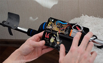
The design and layout of the Pirate metal detector is traditional for equipment of this kind. It is a barbell, at the lower end of which is installed coil, and at the top - electronic unit with a battery.
The location of the electronic unit should leave room for a comfortable hand hold of the rod.
Some craftsmen prefer that the sound signal of the device is given not by the speaker, but by the headphones. In this case, the headphone cable comes off the electronic unit.
The technology of the device is impulse... This makes it possible to provide very good sensitivity indicators for this class of equipment. Below is a diagram of the electronic unit on microcircuits. 
A similar circuit can be assembled using transistors instead of microcircuits. This version may require additional settings available only to experienced radio technicians. This is why the transistor circuit is less commonly used.
Materials, parts and blanks
In addition to the details and precisely indicated on the circuit diagram of the electronic unit of parts, to build metal detector for gold and other metals you need to prepare some materials and blanks:
- a ready-made board for assembling an electronic circuit or foil material for its self-production;
- power supply in the form of any combination of accumulators or batteries with a total voltage of 12V;
- enamel wire with a cross section of 0.5 - 0.6 mm for the manufacture of a coil;
- stranded copper wire for connections with a cross section of at least 0.75 sq. mm;
- housing for the electronic unit - a plastic container of a suitable size;
- strong enough plastic tube for the rod;
- frame for winding the coil;
- consumables - solder, heat-shrinkable cambric, electrical tape, screws and self-tapping screws, adhesives and sealants.
It is best to make a printed circuit board for assembling an electronic circuit according to the model of the developments presented on the Internet.
Below is the one such sample, suitable for assembling electronics on microcircuits.

Lovers of homemade electronics are engaged in the manufacture of the board, and even then not all. Most of those who want to create a metal detector on their own prefer to buy such a part.
For coil assembly requires a frame or frame that does not contain metallic elements. An amateur craftsman can make such a frame from plywood, plastic, or pick up a similar one in parameters from finished plastic products, for example, dishes. The frame can be purchased ready-made or made by yourself
Recommended coil parameters- 25 turns of enamel wire with a diameter of 0.5 mm on a mandrel with a diameter of 190-200 mm. An increase in diameter by 30% will lead to an increase in the sensitivity of the apparatus, provided that the number of turns is reduced to 20-21.
A plastic coil frame is one of the most common metal detector parts on the market.
The coil manipulation technology is such that this very fragile unit can suffer from impacts on uneven ground, stones, sharp objects. To avoid this the coil on the frame is covered from below with a plastic plate... Such a cymbal not only protects the reel, but also provides a sliding mode on tall grass. The search becomes more intense.
Assembly order and design
 For a successful assembly of a metal detector it is best to follow this procedure:
- PCB manufacturing and electronic circuit assembly;
- selection of a plastic container of a suitable size for it and completion of the assembly of the electronic unit;
- coil manufacturing;
- making a rod of a convenient shape and attaching an electronic unit and a coil to it, making connections to an electronic circuit.
Although the assembly order has no fundamental character. For those who make an apparatus for continuous long-term work in the field of searching for non-ferrous metals and subsequent recycling (recycling for reuse), usability is an important factor.
In this case, the study of the shape of the boom and the layout of the main elements of the apparatus becomes a key factor. Thus, a serious design phase appears in the creation of the device.
It is best to accomplish this step of the job with life-size simulation... This simulation can be done using wooden parts of a suitable shape, for example:
- shovel handle;
- plywood pieces of the desired shape;
- scraps from;
- temporary fasteners made of pieces of wire, nails and ropes.
After making sure that the assembled model of the device will be functional and convenient enough, you can proceed to the decisive assembly. Finished apparatus, usually, does not require configuration, it is completely ready to go. You can start searching for metal by choosing the desired level of sensitivity and the correct tactics for manipulating the coil.
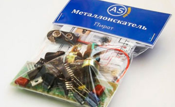 Assemblers who need to assemble their apparatus as quickly as possible, can use ready-made sets of parts.
The purchase of such a kit allows you to significantly simplify the production of the "Pirate". There is one of the proposals.
Users of the Pirate metal detector, who have skills in radio amateur business, modify the design of this device. That's just several directions such improvements:
- Manufacturing coils with unusual parameters- by size, made of special materials, for example - "twisted pair" cable.
- Arrangement of additional functional systems, for example - indication of the degree of discharge of the battery.
- Manufacturing models for underwater work.
- Supplements electronic circuit, distinguishing between metals(creating a discrimination function).
Simple, inexpensive and reliable metal detector "Pirate" works well in a variety of conditions.
Homemade metal detector - pros and cons
Cheapness, basic advantage self-production of any products, relevant for a metal detector. Here are some more dignity from a homemade device:
- the most appropriate search technology for newbies;
- the possibility of creating a device with a completely individual shape, design and configuration;
- the pleasure of making an efficient, workable appliance on your own.
Like any hobbyist device, a metal detector not devoid of some shortcomings.
 Here are the features of the "Pirate" model noted by users:
- energetic charge consumption power accumulators;
- no discrimination, that is, accurate sensitivity to ferrous, non-ferrous and precious metals;
- limited in comparison with expensive models sensitivity.
Despite the shortcomings, the Pirate model is very popular. This is due to the simplicity of homemade manufacturing and the high performance of an inexpensive device.
Recycling professionals believe that the discrimination potential of a metal detector does not matter much. All the metals found are so valuable that recycling is always justified. Focusing on gold prospecting requires not only equipment, but also considerable experience accompanying knowledge and of course good luck.
Related Videos
The video provides a detailed guide for the manufacture and assembly of the Pirate metal detector with your own hands:
Conclusion
When the metal detector is ready, you can start working. We must be aware that no one of the most perfect apparatus will allow finding only golden hidden objects.
The metal detector will help you find valuable metal, and it is very likely that it will be gold. It is best if the prospective metal and gold prospector has a real understanding of the search technique.
Many features of the operation of finished equipment are very important for those who develop and assemble their own models. You need to have an idea of the technology of work in advance with such equipment - this is the basis of its high-quality design.
The effectiveness of gold prospecting increases with experience. Here the most important elements such experience:
- the correct choice of the design of the metal detector and its high-quality do-it-yourself manufacturing;
- the ability to choose the right search site;
- the ability to use the full potential of the metal detector;
- choosing the right search technology in different conditions;
- modernization of the metal detector.
Correctly assembled and debugged equipment will always help in the search for gold, and this valuable metal will certainly be found.
In contact with
1080 878 Search with metal detector Garrett ACE 250 http: //site/wp-content/uploads/2013/11/cda775a0bad3-1259x1024.jpg 01.11.2013 23.03.2018
I decided to wind the coil "on gold". My guess is that it should be a small double-frequency DD coil. If the native coil on the ACE 250 gives about 6.5 kHz, then I will try to develop 11-12 kHz on a "homemade" one.
Let's try to see at what frequency ACE 250 is operating now:
I did so. I wound the probe coil. This is said loudly, because the winding took ... 10 seconds. Here it is: 
There are only 5 turns in the test coil (I took one strand from the so-called "twisted pair"). The picture also shows a connecting cable ("twisted pair" 2 m long) and a connector ("jack" in green electrical tape) - it is needed to connect the test coil to the sound card of the computer. The connector / jack / plug contains two limiting diodes KD103, connected in anti-parallel, they are designed to protect the microphone input of the sound card from interference and overvoltage (according to the results of the first application, it turned out that diodes can be omitted, see below).
Then I needed to turn my computer into a virtual laboratory for a while. I went to this site and took the oscilloscope and frequency counter there - they are the first on the site, as they look, now I will give them below. 
I switched on the ACE 250 with a native 6.5x9 ″ coil and put the coil on a test probe coil, which, in turn, connected it to the computer's sound card to the microphone input (i.e. pulled out the sound cable coming from the webcam and stuck my own). On the screen of the virtual oscilloscope, I saw that the probe, despite its simplicity, catches the signal emitted by the ACEi. It is possible to recalculate in milliseconds what frequency is generated by the ASI coil, but it is better install Wirth. frequency counter and look at it. 
The virtual frequency counter showed a frequency of 6700 Hz.
conclusions: the test coil-probe is working, the virtual devices also coped with their task. Judging by the shape of the signal on the oscilloscope, the probe has sufficient sensitivity, in addition, it can be concluded that the protective diodes (KD103) are not needed: the signal overload is not observed on the oscillogram, although the probe was close to the emitting coil. The shown probe works even from the microphone input of the sound card, even from the linear one (I have it integrated into the motherboard).
We have the devices. (I recently noticed that the shown virtual frequency counter could not work with WINDOWS7 (x64), so I advise you to use the virtual spectrum analyzer Simple Audio Spectrum Analyzer to measure the frequency specan22 from this site, the program also works under WINDOWS-10). Now you can move on to the practical part, namely: wind a small coil (one half of the future DD coil) and connect it to the generator part of the ASI circuit, reach a resonance of 12 kHz.
I wound this coil of twisted pair wires. 
There are 9 turns of this cable without an outer sheath, i.e. 9 x 8 = 72 turns, respectively, soldered "end-start". I connect the output of the coil through a 1.1 Ohm safety resistor to the contacts of 1.4 of the connector (I bought it for 5 UAH). In order not to excite the ASI input, I temporarily solder a 10 Ohm resistor to contacts 2,3 (to which the Rx coil will be connected). Here's a schematic: 
I plug in the connector and turn on the ACE 250 - it beeped twice and turned on as usual, without noticing the substitution. The oscilloscope showed the presence of the generation of the "newly appeared" Tx coil (the signal was taken with a test coil-probe): 
And the frequency counter showed the expected frequency: 
The sound card was a little capricious - it did not want to recognize the test probe coil as a microphone, I had to deceive it by soldering a 10 kOhm resistor and a 0.47 uF capacitor to the coil, see the pictures: 

I made the receiving coil 11 x 8 = 88 turns (I found a "twisted pair" of a slightly thinner diameter, so the coils seem to be the same, although there are 22% more turns on Rx).
Now we have both halves of the DD coil, let's check the possibility of "converging" the coils.
I connected the Tx coil to the ACE 250 (see in the previous message the circuit for starting the Tx coil from the ACE 250 generator), and connected a multimeter to the output of the Rx coil in the AC voltage measurement mode. Moving one coil relative to the other, you can easily get three zeros after the decimal point in the alternating voltage on the receiving coil, i.e. "Mixing" the coils is done without problems. Outlined the relative position on the underlying sheet of paper in order to roughly transfer the configuration to the future "bed". 

The coils turned out to be "plump" - when they are round, they have a diameter of exactly 10 cm from edge to edge, they can be easily turned into oval ones:
For the sake of beauty, I introduced a multimeter into the frame, but mixing with it does not work. However, if you remove the measuring device by 30 centimeters, then by mutual displacement of the coils, you can easily achieve "zeros" on the display (ie, the imbalance is less than 0.001 V).
Finally, I will make the DD coil on oval coils: the sensitivity will be lower than on round coils, but judging even by these images, the "through-hole" zone of the ground with oval coils is 50 percent larger.
The main estimates have been made, editing is coming soon.
Do not think that I am using junk cheap materials, in fact, the opposite is true - these are the best materials. The coils are made with wire in thick polyethylene insulation with a twist, which helps to reduce the turn-to-turn capacitance and, as a result, gives a high Q-factor, which means a well-pronounced inductive effect and a large circulating current in the Tx transmitter coil, a high Q-factor is also useful for the Rx receiving coil ... The coils are "loose", i.e. there is no mechanical stress in the wire - this gives increased thermal stability. (When heated, polyethylene will "move", where to the outside, where to the inside and the total area of the coil will remain unchanged, which means that L = const, R will change when heated, you cannot leave the formulas, but it will change less than in simple coils, since there is initially no mechanical tension). There are other positive effects (for example, no aging of the wire insulation due to magnetostriction - it is because of this that the varnish on ordinary winding wires wears out). The coils were wound without any tricks, in one minute, on an ordinary coffee can. It is also important that in the assembled structure, in addition to the wire, there will be no radio components (and remember whole boards with radio components and trimming resistors (!) In coils from "brands"). Even higher parameters can be obtained using a twisted-pair cable for computer networks, in which each core is made of a stranded wire - but I did not find one on sale, but this one was just at hand.
Very modest expenses had to be incurred for the manufacture of a connecting cable (connector - 5 UAH shielding the coil with the "ground" of the ASI unit - also in fluoroplastic insulation, stranded MGTF - 2 mx 1 UAH = 2 UAH. Heat-shrinkable tubes were only meter-long - 4 more UAH). As a result, the cable together with the connector cost UAH 19. 
The cable is the best of all possible (without exaggeration): each coil will be connected to the ACE 250 unit with two shielded cables, the signal will not run through the screens, the ground connecting the ACE 250 unit ground to the static screen of the DD coil goes separately wire from the pin 5 of the connector (see diagram). All wires of the connecting cable are MGTF. (The radio amateur will immediately notice that the "ground" is divorced by the "spider" - thus, all the interference that came from the environment in different phases and amplitudes will be mutually subtracted at point 5 of the connector).
(For reference: all spacecraft cabling is done only wire MGTF).
So the dug graphite came in handy))). It weighs 20 kilograms, apparently from an electrolysis bath, there are 3 holes on top for connecting a cable.

Both the coils and the bed are shown here. The bed / slipway / substrate is fiberglass, 3 mm thick, the installation of the coils on it means that there will be no work from the bottom of the future DD coil - in fact: put the coils Rx, Tx on the bed, bring together, fix it with epoxy with fiberglass and EVERYTHING ...
In the morning I went to the garden, sawed off a piece of graphite from my "super-deposit" and took further steps along the reel. 


I took a 10 mm drill bit, drilled a hole and a little dispersed it is in a cube of graphite, and the resulting powder is collected. I wrapped cotton thread around the Rx coil to improve adhesion with PVA glue. I mixed the glue with graphite powder in a ratio of 50 to 50 and covered the Rx coil with this mixture. I put the smeared coil on the designated place on the "bed" and put it to dry. I will not smear the Tx coil with an antistatic agent at all.
The Rx coil, which was coated yesterday with "antistatic", has dried out. I checked the resistance of the graphite screen: 

I cut the screen (there is a red strip from the insulating tape there) and took up the connecting cable.
After I made the connecting cable (I pulled 4 shielded wires and one simple one into a heat shrink tube) and unsoldered everything (both coils and a screen wire, see the diagram above), then connecting the connector to the ACE 250 and making sure that everything works (the frequency dropped to 11 kHz), reduced the coils to an imbalance of 1 mV and tested a DD coil with a gold earring on the table in comparison with the native coil from ACE 250.
Bottom line. For a buttoned gold earring it became 17 cm, and it was 13, for an unbuttoned one: it became 7 cm, and it was 5. The longitudinal size of the 6.5x9 "asyn" coil is 22.5 cm, and mine, 5x5.8 ", is only 12 cm.
It is interesting that the discrimination scale has shifted strongly in the field of ferrous metals (expanded), and since the USSR penny, it has remained the same and in its place, 5 kopecks. USSR and 50 kopecks ukr. - respond with "bellton", but the Ukrainian nickle. from stainless steel moved one cell to the right (2 cell of the scale). Pinpoint is working. I also noticed that the chuyka fell by 25 kopecks, 50 kopecks and 50 kopecks and a nickle of the USSR, in comparison with the native reel, and increased by gold, i.e. the gold "protruded" against the background of the walker, as it was intended.


If you click on the left frame - this is the first step in filling the coil with epoxy with glass cloth - you can see the “ground” retraction from the screen. It is a bare copper wire, 10 cm long, fused in places with a soldering iron into a graphite screen.
In the meantime, I repaired my own "asina" coil, there were nicks, and with the remaining black putty (epoxy with powder from a SAMSUNG laser printer) I glued a couple of glass cloth patches to the sensor. My baby is moving to the finish line, I will soon take him out for a walk, and breathe in the sea air, though I didn't guess something with epoxy - it dries slowly. Please note that the Rx and Tx coils remained virtually not impregnated with epoxy to the wires - this is how it was intended - this is also weight saving, but the main thing is to maintain the highest electrical quality factor Q. We get an armored body made of epoxy resin with fiberglass, but the coils themselves are dry, epoxy did not reach them.
Below I give a comparison of the main parameters of the new home-made "coil for gold" and a small native coil from ASI (I show two screen the specan22 program).

The coil more or less turned out, after checking the new coil made on the nearest beach (it showed 10 cm on the capsule in the sand, which made me very happy), I immediately wanted to ride on the beach and really run with it. 
The first vacationers appeared on the city beach of Kerch, so I chose a quiet corner outside of it. This place had been surveyed a couple of days earlier with two coils (6.5x9 ″ and NEL Tornado), however, my homemade baby suddenly began to pull out pennies of the USSR and Ukrainian dimes. It was clear with Ukrainian stainless steel dimes - earlier, if you turn off the first square of the discrimination scale, the device saw them, but did not sound them, because it considered them black metal, and a new coil operating at a frequency of 11 kHz "stretched" the left side of the metal scale (as at Ace 350 Euro) and began to squeak "in color" on a stainless steel. But the pennies of the USSR really became an indicator of the quality of my coil, because some jumped out from a depth of 15 cm and were clearly missed by me earlier, when I walked with my own and "tornado" coils. Despite its small size, the coil showed a fairly large coverage, similar to the usual one from the native Asev coil 6.5x9 "(along the central line, the coverage was 18 cm for a 10 kopeck coin lying on the surface of the sand), so I did not have to compact steps when searching. 
Then came across an openwork silver chain. I'm not sure if I could find it with my own Asev coil (I will have to check). 
I found a silver chain somewhere here.
I liked the sharp sound and sharp reaction to the target, probably typical for this type of coil.
The clouds began to thicken, a cold breeze blew out, and in order not to get caught in the downpour, I drove home. 
Modest findings from testing. The gold medallion was raised two days earlier with the help of my native ACEv coil, I am showing it because I also tested my “coil for gold” on it.
The frequency response of the coil is shown in comparison with other coils (practical screenshots programs specan22 of some coils for ASI in comparison with this new-made "coil for gold").
I started the article in December 2013, but I did the final test of the coil's reaction to small gold only at the beginning of June 2014, together with a friend.
And you can see this coil in comparison with the factory coils for the ACE 250.
And the operation of the coil on the beach in 2017 is shown.
— — — — — — — — — — — —
In March 2015, I received questions. In no way do I think that there are stupid questions, but I think that there are stupid answers.
Let's start with the first question.
1. Connecting the headphone jack to which pins, or no difference?

Answer: does not matter. Solder the "jack", plug it into the input to the sound card of the computer and the probe will begin to receive the frequencies emitted by the coils of the metal detectors, and the computer, turned into an analyzer, will "figure it out" and show the frequency. there is a slightly different diagram of the probe and details with the work in the program specan22.
2. How are the wires on the coils soldered? 8 in one or in colors with each other? How did you get 2 outputs?
Answer:

This is the future Tx radiating coil (the second Rx coil will be made on the same principle).
In the main text (see above) I write: “There are 9 turns of this cable without an outer sheath, that is. 9 x 8 = 72 turns, respectively, soldered "end-start".
Let's describe in more detail.
First, I wound 9 turns of cable on a coffee can (diameter, about a liter glass jar), then I removed the coil, grabbed it in four places with white electrical tape and began to unsolder. Those. before starting work on turning into a single coil of 72 turns, I had 8 separate coils with 9 turns in each (or 8 "beginnings" and 8 "ends" lying opposite each other - I divided them with a conditional red line), which I had to combine into one coil.
Let's deal now with this particular shot of the coil, although it is not very successful for demonstration.
We take the first vein of "beginnings" that comes across - I have a green vein (it dives into the coil in the upper half of all "beginnings" and is indicated by a red arrow), now we find this green vein among the "ends" at the bottom of the coil (i.e. our green vein made 9 turns and finally, emerged among the "ends" - I also marked it with a red arrow) and this "end" of it and soldered to the "beginning" of any other vein (if you click on the frame and look closely, you can see that the end of the green vein is soldered with the beginning of some next vein and an insulating tube with an asterisk is put on the jumper). Then we find the end of the second vein and connect it to the beginning of some third vein. We will have to do such operations 7 times under the record, i.e. make 7 splices of the cable veins until there is only one "end" that has nowhere to solder - in the picture it is a white vein with a green vein.
As a result, we get a single coil of 72 turns, in which the "beginning" is a green vein and the "end" is a white vein with a green vein.

Recently I saw this picture and took it to my website - this is how you need to bend the ends to get a single coil, it is clear that there are different colors of the beginning and end of the coil.
3. From the coil 2 outputs. What is where to solder on the connector? Or does it matter?
Answer: On each coil there are 2 outputs, in order to test the future Tx coil for frequency generation and measure it, the coil must be thrown to the pins 1, 4 of the connector, the connector should be plugged into the ACU. The finished coil will have 4 outputs, the pinout to the connector is shown in the text. For a long time it will not matter how the ends are soldered - you will already complete the coil, you will go to the beach to test it (and do the finishing operation of mixing, as I recommend to the most inquisitive designers) and only then you will need to cross the ends on the connector and test the pinpointer in work with Colored targets. In the literature, this finishing operation is called "phasing" the coils. I don’t need any instruments, opponents cannot do without a separate generator, oscilloscope and other instruments. A correctly phased sensor does not move the pin away from the object, but clearly shows that the target lies in the intersection of the windings.
4. Does the resistor remain on the TX coil after checking on the computer and the assembly on the substrate?
Answer: No, I put this 1.1 Ohm resistor solely to estimate the frequency and not to accidentally burn the ACE 250. There are no resistors, capacitors and nothing at all on the working coil, only the coils themselves.
5. How to check the resistance on the graphite screen correctly? And why cut the graphite screen?
Answer:
The picture shows that I just pressed the probes to the graphite screen at opposite points of the coil, the device showed a resistance between the probes a little more than 1 kOhm - this is quite normal resistance. The screen will work fine with a resistance of 10 kOhm. It is designed so that colossal static charges of tens of thousands of volts flow down through it to the "ground" of the MD, therefore the resistance of the shielding coating of the Rx coil is not of fundamental importance.
The annular cut is needed so that a closed loop (coil) does not form in the form of a graphite screen. Despite the rather high resistance of the screen, it seems to me that such a cut should be made. Different authors think differently. I tried to get the most out of this coil at every step, so I made a cut in the screen so that the screen would not in any way be a closed VITC on this coil.
6. Is it worth covering the coil with a graphite screen?
Answer: I left the TX coil without the screen. I believe that the screen will, at least slightly, reduce the signal that will be "pumped" into the ground. Further tests showed a neutral response to static electricity - i.e. it is really sufficient to screen only the Rx receive coil.
7. What are the dimensions of the coil mounting lugs? What were they made of and what were they glued to? What is the cross on the backing and how was it calculated?
Answer: It seemed to me that the ears should be attached directly to the bed / substrate and should not be mechanically connected to the coils. I prepared the seats on the ends of the bed and first glued these 2 ears on some kind of glue, and then reinforced them with epoxy with fiberglass in the process of forming the entire coil. The ears are cut from a sheet of PCB, 0.5 cm thick. The distance between them is not standard for ACE 250. The ears are clearly visible if you click on the corresponding frames above. The lower rod knee assembly is made from a T-shaped garden hose splitter and is cut to fit between the lugs with friction. The cross on the backing means almost nothing, it was just clearly visible through the paper sheet, on which I did the initial mixing of the coils and outlined their relative position.
8. Regarding the cable: did you heat shrink with a hairdryer? How and how was the cable attached to the coil? Well, the main question: HOW did you solder the cable? They just connected 4 outputs from the coils and soldered to the connector, and to what was the 5th cable attached to the finished coil?
Answers: I warmed the shrink tubing over a regular electric cooker.
The cable simply sank into layers of epoxy with fiberglass, and was fixed on the coil.
I have done better wiring of the cable than in any factory or home-made coil. Now I will gradually explain why, although I will not describe physics.
First, I will characterize the wire itself, which formed the basis of the connecting cable: I have used 4 identical lengths of MGTF shielded wire and one piece of unshielded MGTF wire, all of them have a length of 1.5 m.This is the best existing stranded wire (in my 24 very thin copper veins with a diameter of 0.08 mm, and its insulation can withstand the temperature of the soldering iron, since it is made of fluoroplastic; its shielding braid (sometimes I just write "shield") is silver-plated copper, in short, it is an excellent "military" wire).

And secondly, let's turn to the wiring of the connecting cable, which is shown in the blue frame. It can be seen that all shielded wires are prepared in the same way, as shown in the red box, namely: the left end has no shield terminal (only the wire itself), and the right end has a shield terminal, and all such shield terminals of the four wires are collected at one point, indicated by a circle. For complete clarity of perception, I will add that the cylinder in the red frame is the wire screen, and the signal wire itself passes inside the cylinder, as it is customary to designate on most circuits in the world and ess-but, the wire is isolated from the shielding braid (screen), the insulator is a fluoroplastic film ...
It remains only to deal with the fifth wire, which does not have a screen (but has insulation). Its left end is shown by such a "chicken paw" - in this place the wire has contact with the graphite coating of the Rx coil - the wire there is stripped and glued (more precisely, melted with a soldering iron tip) at several points to the graphite screen. As tempting as it is to run this contact through any of the four-wire shields (and many factory coils do this to save copper), I do it with a separate wire (and also of the highest quality).
What do we get as a result of unsoldering the connecting cable? - all ends of all coils are run along shielded wires, each along its own wire, all the shielding braids of the wires and the wire coming from the shielding of the Rx receiving coil are soldered at one point (and then connected through the 5th pin of the connector to the main "ground" on the MD board) ...
The resulting homemade cable is wrapped with electrical tape along its entire length and then pulled through a heat-shrinkable tube.
Theoretically, the parameters of the connecting cable can still be improved if you use not just shielded wires, but each of them is additionally insulated along the entire length (my wires had a bare braided shield).
9. Could you tell us more about mixing coils? Interested in how to connect a tester if the plug and coils are soldered to the cable?
Answer: You need to measure (and nullify) the AC voltage at the output of the Rx receive coil and preferably in the field. But first, everything needs to be tested on the table in order to make a drawing of the relative position of the coils, and according to the drawing, make a bed / substrate.
The pins of connector 1, 4 are now going to the ASI unit and from it the Tx coil is started to generate. The induction voltage is induced in the receiving coil Rx and when tuning / converging the coils should be minimized (to all zeros on the tester). In practice, do this: do not touch pins 1, 4, and completely unsolder the Rx coil pins from the pins 2, 3 of the connector and connect (solder the probes) the tester to these wiring in the AC voltage measurement mode. After obtaining a "zero" voltage at the output of the Rx coil, sketch out the relative position of the coils and, based on the figure, cut out the bed / substrate. Then glue the Rx coil to it (it should already be in the graphite screen, and the screen is connected with a wire to the pin 5 of the connector), now you can go to the beach to set "zero" as accurately as possible, taking into account the influence of the earth. (In ACE 250 there is no ground balance, it is set only once "on average" at the factory, therefore, by making a coil with a pre-compensated ground effect, you will significantly improve the parameters of the MD set by the factory. ).
In the field you need to find abs. a place that is clean from metal debris (your own coil will help you here), then put a new coil on the sand and “mix”, like at home, on the table, i.e. connect the coil according to the above-described method, carry out “convergence” to four zeros on the device, and after “converging the coils” fix their position on the substrate with glue. Keep the tester away from the coil. The glue for fixing the end position of the coils should be used not plastic (it can "float" when the coil is operated in the heat), but best of all of the "droplet" type, which is sold in small tubes. Upon arrival home, you can already apply the first layer of epoxy with fiberglass.
The lower leg of the boom was made from a suitable polyethylene tube. This knee is frictionally put on an aluminum bar and does not have any other fastening elements. The ends of the knee are reinforced with epoxy with fiberglass.
And the last thing. If I started making this reel now, I would give a much larger allowance for the "bed". What's wrong with the fact that it was she who would meet all sorts of obstacles in the path of the coil's movement? - then the coil (the protruding edge of the bed / substrate) could literally dig the sand.
All pictures are "clickable".
Let's start by making the device with which we will wind the coil. We need a piece of board measuring at least 18 by 18 centimeters, nails and cambric. The nails should be of such a diameter that the cambric fits loosely enough on them.
Draw a circle with a diameter of 16 centimeters on the board and drive in at least 16 nails in a circle, evenly distributing them. The nails should be at least two centimeters out of the board. We bite off the caps at the nails, put cambric on the nails. The length of the cambric should be equal to or slightly longer than the length of the protruding nail. The device is ready.
As you understand, the diameter of our coil is 16 cm. We will wind it with a copper wire with a diameter of about 0.3 mm. We wind 80 turns of wire on our device, then we pull the resulting coil in 12 places with thick threads and remove it from the device. If the coil is impregnated with epoxy resin, the frequency stability of the search generator will increase and the coil will be reliably protected from moisture ingress.
The length of the coil leads should be about 4 cm. When winding, the turns should not be too tight, but they should not dangle either. We wrap the coil tightly with one layer of electrical tape, but so that the turns are not stretched. To do this, we first wrap the coil in eight places with small pieces of electrical tape.

Now we need to make a screen for the coil, for this I use foil strips from electrolytic capacitors. The foil must be rinsed with water to remove the electrolyte and dried. We wrap the coil with foil, leaving a gap in the area of the coil terminals. The screen should not dangle on the coil. We fix the end of the screen with electrical tape.

We take a piece of copper wire, about 0.5 mm in diameter, 125 cm long. We remove the varnish with sandpaper and iron it along the entire length. Next, we tightly wrap the coil over the screen with this wire, with a step of about 1 cm, having previously left a lead 12 cm long. Between the beginning and the end of the winding, it is necessary to leave a gap in the area of the coil leads.
A device that allows you to find metal objects located in a neutral environment, for example, ground, due to their conductivity, is called a metal detector (metal detector). This device allows you to find metal objects in various environments, including the human body.
Largely due to the development of microelectronics, metal detectors, which are produced by many enterprises around the world, have high reliability and small overall and weight characteristics.
Not so long ago, such devices could most often be seen at sappers, but now they are used by rescuers, treasure hunters, utility workers when searching for pipes, cables, etc. Moreover, many "treasure hunters" use metal detectors that they collect with their own hands ...
Design and principle of operation of the device
The metal detectors on the market work on different principles. Many believe that they use the principle of pulsed echo or radar. Their difference from locators lies in the fact that the transmitted and received signals operate constantly and simultaneously, in addition to everything else, they work at coinciding frequencies.
Devices operating on the "receive-transmit" principle register the reflected (re-emitted) signal from a metal object. This signal appears due to the effect on a metal object of an alternating magnetic field, which is generated by the metal detector coils. That is, the design of devices of this type provides for the presence of two coils, the first is transmitting, the second is receiving.
Devices of this class have the following advantages:
- simplicity of design;
- great opportunities for the detection of metallic materials.
At the same time, metal detectors of this class have certain disadvantages:
- metal detectors can be sensitive to the composition of the ground in which they are searching for metal objects.
- technological difficulties in the manufacture of the product.
In other words, devices of this type must be configured by hand before work.
Other devices are sometimes referred to as a beat detector. This name came from the distant past, more precisely from the times when superheterodyne receivers were widely used. Beating is a phenomenon that becomes noticeable when two signals with similar frequencies and equal amplitudes are added together. The beating consists in the pulsation of the amplitude of the summed signal.
The signal ripple frequency is equal to the frequency difference of the summed signals. Passing such a signal through a rectifier, it is also called a detector, the so-called difference frequency is isolated.
This scheme has been used for a long time, but nowadays, it is not used. They were replaced by synchronous detectors, but the term remained in use.
A beating metal detector works using the following principle - it registers the frequency difference from two transmitter coils. One frequency is stable, the other contains an inductor.
The device is tuned with your own hands so that the generated frequencies match or at least be close. As soon as the metal enters the zone of action, the set parameters change and the frequency changes. The frequency difference can be recorded in a variety of ways, ranging from headphones to digital methods.
Devices of this class are distinguished by a simple sensor design, low sensitivity to the mineral composition of the soil.
But besides this, during their operation, it is necessary to take into account the fact that they have high energy consumption.
Typical design
The metal detector includes the following components:
- The coil is a box-type construction that houses the receiver and transmitter of the signal. Most often, the coil has an elliptical shape and polymers are used for its manufacture. A wire is connected to it, connecting it to the control unit. This wire carries the signal from the receiver to the control unit. The transmitter generates a signal when metal is detected, which is broadcast to the receiver. The coil is mounted on the lower shaft.
- The metal part, on which the coil is fixed and the angle of its inclination is adjusted, is called the lower shaft. Thanks to this solution, a more thorough examination of the surface occurs. There are models in which the lower part can adjust the height of the metal detector and provides a telescopic connection to the rod, which is called the middle one.
- The middle boom is the node located between the lower and upper boom. Devices are fixed on it, allowing you to adjust the dimensions of the device. on the market you can find models that consist of two rods.
- The top bar is usually curved. It resembles the letter S. This shape is considered optimal for fixing it on the hand. An armrest, a control unit and a handle are installed on it. The armrest and the handle are made of polymer materials.
- The metal detector control unit is required to process the data received from the coil. After the signal has been converted, it is sent to headphones or other display devices. In addition, the control unit is designed to adjust the operating mode of the device. The wire from the coil is connected using a quick-release device.
All devices included in the metal detector are waterproof.
It is such a relative simplicity of the design that allows you to make metal detectors with your own hands.
Varieties of metal detectors
There is a wide range of metal detectors on the market that are used in many areas. Below is a list showing some of the variations of these devices:
Most modern metal detectors can find metal objects at a depth of 2.5 m, special deep products can detect a product at a depth of 6 meters.
Work frequency
The second parameter is the frequency of operation. The thing is that low frequencies allow a metal detector to see at a rather large depth, but they are not able to see small details. High frequencies allow you to see small objects, but do not allow viewing the ground at great depths.
The simplest (budget) models operate at one frequency, models that belong to the average price level use 2 or more frequencies in their work. There are models that use 28 frequencies when searching.
Modern metal detectors are equipped with such a function as metal discrimination. It allows you to distinguish the type of material located at depth. In this case, when a ferrous metal is found in the search engine's headphones, one sound will sound, and when a colored metal is found, another.
Such devices are referred to as pulse-balanced. They use frequencies from 8 to 15 kHz in their work. Batteries of 9 - 12 V are used as a source.
Devices of this class are capable of detecting a gold object at a depth of several tens of centimeters, and items made of ferrous metals at a depth of about 1 meter or more.
But, of course, these parameters depend on the device model.
How to assemble a homemade metal detector with your own hands
There are many models of devices on the market for searching for metal in the ground, walls, etc. Despite its external complexity, making a metal detector with your own hands is not so difficult and almost anyone can do it. As noted above, any metal detector consists of the following key components - a coil, a decoder and a power supply signaling device.
To assemble such a metal detector with your own hands, you need the following set of elements:
- controller;
- resonator;
- capacitors of various types, including film;
- resistors;
- sound emitter;
- Voltage regulator.
Do-it-yourself simple metal detector
The metal detector circuit is not complicated, but you can find it either on the vastness of the world network, or in specialized literature. Above is a list of radioelements that are useful for assembling a metal detector with your own hands at home. A simple metal detector can be assembled by hand using a soldering iron or other available method. The main thing is that the details should not touch the body of the device. To ensure the operation of the assembled metal detector, power supplies of 9 - 12 volts are used.
For winding the coil, a wire with a cross-sectional diameter within 0.3 mm is used, of course, this will depend on the chosen scheme. By the way, the wound coil must be protected from the effects of extraneous radiation. To do this, they shield it with their own hands using ordinary food foil.
For the controller firmware, special programs are used, which can also be found on the Internet.
Metal detector without microcircuits
If a novice "treasure hunter" has no desire to get involved with microcircuits, there are circuits without them.
There are simpler circuits based on the use of traditional transistors. Such a device can find metal at a depth of several tens of centimeters.
Deep metal detectors are used to find metals at great depths. But it is worth noting that they are not cheap and therefore it is quite possible to assemble it with your own hands. But before you start making it, you need to understand how a typical scheme works.
The circuit of a deep metal detector is not the simplest one and there are several options for its design. Before assembling it, you need to prepare the following set of parts and elements:
- capacitors of various types - film, ceramic, etc.;
- resistors of different ratings;
- semiconductors - transistors and diodes.
Nominal parameters, quantity depend on the selected circuit diagram of the device. To assemble the above elements, you will need a soldering iron, a set of tools (screwdriver, pliers, wire cutters, etc.), material for making a board.
The assembly process for a deep metal detector looks like this. First, a control unit is assembled, the basis of which is a printed circuit board. It is made of PCB. Then the assembly diagram is transferred directly to the surface of the finished board. After the drawing is transferred, the board must be etched. For this, a solution is used, which includes hydrogen peroxide, salt, electrolyte.
After the board has been etched, holes must be made in it to install the circuit components. After the board has been tinned. The most important stage is coming. Do-it-yourself installation and soldering of parts to the prepared board.
To wind the coil with your own hands, use a PEV brand wire with a diameter of 0.5 mm. The number of turns and the diameter of the coil depend on the chosen scheme of the deep metal detector.
A little about smartphones
There is an opinion that it is quite possible to make a metal detector from a smartphone. This is not true! Yes, there are applications that are installed under the Android OS.
But in fact, after installing such an application, he will actually be able to find metal objects, but only pre-magnetized ones. He will not be able to search and even more to discriminate against metals.
 New rules for personal property tax
 Features of the sale of an apartment with illegal redevelopment
 Rules and procedure for the exam