How to lower the voltage: methods and devices. Power supply How to make 30 volts from 12 volts
You need to know how to lower the voltage in the circuit so as not to damage electrical appliances. Everyone knows that two wires are suitable for houses - zero and phase. This is called single-phase is extremely rarely used in the private sector and apartment buildings. There is simply no need for it, since all household appliances are powered by a single-phase alternating current network. But in the technique itself, it is required to make transformations - to lower the alternating voltage, convert it to a constant one, change the amplitude and other characteristics. These are the points that need to be considered.
Voltage reduction with transformers
The easiest way is to use a low voltage transformer that does the conversion. The primary winding contains more turns than the secondary. If there is a need to reduce the voltage by half or three times, the secondary winding can not be used. The primary winding of the transformer is used as an inductive divider (if there are taps from it). In household appliances, transformers are used, from the secondary windings of which voltage of 5, 12 or 24 Volts is removed.
These are the most commonly used values in modern household appliances. 20-30 years ago, most of the equipment was powered by a voltage of 9 volts. And tube TVs and amplifiers required a constant voltage of 150-250 V and an alternating voltage of 6.3 for the filaments (some lamps were powered by 12.6 V). Therefore, the secondary winding of the transformers contained the same number of turns as the primary. In modern technology, inverter power supplies are increasingly used (as on computer power supplies), their design includes a step-up type transformer, it has very small dimensions.
Voltage divider on inductors

An inductance is a coil wound with (usually) copper wire on a metal or ferromagnetic core. A transformer is a type of inductance. If a tap is made from the middle of the primary winding, then there will be an equal voltage between it and the extreme terminals. And it will be equal to half the supply voltage. But this is the case if the transformer itself is designed to work with just such a supply voltage.
But you can use several coils (for example, you can take two), connect them in series and turn them on to the AC network. Knowing the values of inductances, it is easy to calculate the drop on each of them:
- U(L1) = U1 * (L1 / (L1 + L2)).
- U(L2) = U1 * (L2 / (L1 + L2)).
In these formulas, L1 and L2 are the inductances of the first and second coils, U1 is the supply voltage in Volts, U(L1) and U(L2) are the voltage drop across the first and second inductances, respectively. The scheme of such a divider is widely used in the circuits of measuring devices.
capacitor divider

A very popular circuit used to reduce the value of an AC mains supply. It cannot be used in DC circuits, since the capacitor, according to Kirchhoff's theorem, in a DC circuit is a break. In other words, no current will flow through it. But on the other hand, when working in an alternating current circuit, the capacitor has a reactance, which is able to extinguish the voltage. The divider circuit is similar to the one described above, but capacitors are used instead of inductors. The calculation is made according to the following formulas:
- Capacitor reactance: X(C) = 1 / (2 * 3.14 * f * C).
- Voltage drop across C1: U(C1) = (C2 * U) / (C1 + C2).
- Voltage drop across C2: U(C1) = (C1 * U) / (C1 + C2).
Here C1 and C2 are the capacitances of the capacitors, U is the voltage in the supply network, f is the frequency of the current.
resistor divider
The circuit is in many ways similar to the previous ones, but fixed resistors are used. The method for calculating such a divisor is slightly different from those given above. The circuit can be used in both AC and DC circuits. We can say that it is universal. With its help, you can assemble a step-down voltage converter. The calculation of the drop across each resistor is made using the following formulas:
- U(R1) = (R1 * U) / (R1 + R2).
- U(R2) = (R2 * U) / (R1 + R2).
One caveat should be noted: the value of the load resistance should be 1-2 orders of magnitude less than that of dividing resistors. Otherwise, the accuracy of the calculation will be very rough.
Practical power supply circuit: transformer

To select a supply transformer, you will need to know a few basic data:
- The power of consumers to be connected.
- The value of the mains voltage.
- The value of the required voltage in the secondary winding.
S = 1.2 *√P1.
And the power P1 \u003d P2 / efficiency. The efficiency of the transformer will never be more than 0.8 (or 80%). Therefore, the calculation takes the maximum value - 0.8.
Power in the secondary winding:
P2 = U2 * I2.
These data are known by default, so it will not be difficult to calculate. Here's how to step down the voltage to 12 volts using a transformer. But that's not all: household appliances are powered by direct current, and at the output of the secondary winding - alternating current. You will need to make a few more transformations.
Power supply circuit: rectifier and filter

The next step is to convert AC to DC. For this, semiconductor diodes or assemblies are used. The simplest type of rectifier consists of a single diode. It is called one-half-wave. But the bridge circuit has gained maximum distribution, which allows not only to straighten the alternating current, but also to get rid of ripples as much as possible. But such a converter circuit is still incomplete, since one cannot get rid of the variable component with semiconductor diodes alone. And step-down transformers are able to convert alternating voltage into the same frequency, but with a lower value.
Electrolytic capacitors are used in power supplies as filters. According to Kirchhoff's theorem, such a capacitor in an alternating current circuit is a conductor, and when working with a constant current, it is a break. Therefore, the constant component will flow unhindered, and the variable will close on itself, therefore, it will not go beyond this filter. Simplicity and reliability are exactly what characterizes such filters. Resistances and inductances can also be used to smooth out ripples. Similar designs are used even in automotive generators.
Voltage stabilization

You have learned how to lower the voltage to the desired level. Now it needs to be stabilized. For this, special devices are used - zener diodes, which are made of semiconductor components. They are installed at the output of the DC power supply. The principle of operation is that the semiconductor is able to pass a certain voltage, the excess is converted into heat and released through the radiator into the atmosphere. In other words, if the PSU output is 15 volts, and a 12 V stabilizer is installed, then it will skip exactly as much as it needs. And the difference of 3 V will go to heat the element (the law of conservation of energy is valid).
Conclusion
A completely different design is a step-down voltage regulator, it makes several transformations. First, the mains voltage is converted to DC with a high frequency (up to 50,000 Hz). It is stabilized and fed to a pulse transformer. Then there is a reverse conversion to the operating voltage (mains or smaller in value). Thanks to the use of electronic keys (thyristors), the direct voltage is converted into alternating voltage with the required frequency (in the networks of our country - 50 Hz).
How to assemble a simple power supply and a powerful voltage source yourself.
Sometimes you have to connect various electronic devices, including homemade ones, to a 12 volt DC source. The power supply is easy to assemble on your own during half a day off. Therefore, there is no need to purchase a ready-made block, when it is more interesting to make the necessary thing for your laboratory yourself. 

Anyone who wants to be able to make a 12-volt unit on their own, without much difficulty.
Someone needs a source to power the amplifier, and someone needs to power a small TV or radio ...
Step 1: What parts are needed to assemble the power supply...
To assemble the block, prepare in advance the electronic components, parts and accessories from which the block itself will be assembled....
-Circuit board.
- Four diodes 1N4001, or similar. The bridge is diode.
- Voltage stabilizer LM7812.
- Low-power step-down transformer for 220 V, the secondary winding should have 14V - 35V AC voltage, with a load current of 100 mA to 1A, depending on how much power you need to get at the output.
- Electrolytic capacitor with a capacity of 1000uF - 4700uF.
- 1uF capacitor.
-Two 100nF capacitors.
- Cut wires.
-Radiator, if needed.
If you need to get the maximum power from the power supply, you need to prepare the appropriate transformer, diodes and heatsink for the chip.
Step 2: Tools....
For the manufacture of the block, tools for installation are required:
-Soldering iron or soldering station
-Nippers
- Mounting tweezers
-Wire strippers
- Solder suction device.
-Screwdriver.
And other tools that you might find useful.
Step 3: Schematic and more... 
To get a 5 volt stabilized power supply, you can replace the LM7812 stabilizer with the LM7805.
To increase the load capacity by more than 0.5 amperes, you will need a heatsink for the microcircuit, otherwise it will fail from overheating.
However, if you need to get a few hundred milliamps (less than 500 mA) from the source, then you can do without a heatsink, heating will be negligible.
In addition, an LED is added to the circuit to visually verify that the power supply is working, but you can do without it.

Power supply circuit 12v 30A.
When using one 7812 stabilizer as a voltage regulator and several powerful transistors, this power supply is capable of providing an output load current of up to 30 amperes.
Perhaps the most expensive part of this circuit is the power step-down transformer. The voltage of the secondary winding of the transformer must be a few volts more than the stabilized voltage of 12V in order to ensure the operation of the microcircuit. It must be borne in mind that one should not strive for a larger difference between the input and output voltage values, since at such a current the heat sink of the output transistors increases significantly in size.
In the transformer circuit, the diodes used must be designed for a large maximum forward current, approximately 100A. The maximum current flowing through the 7812 chip in the circuit will not exceed 1A.
Six composite Darlington type TIP2955 transistors connected in parallel provide a load current of 30A (each transistor is rated for a current of 5A), such a large current requires an appropriate size of the radiator, each transistor passes through itself one sixth of the load current.
A small fan can be used to cool the radiator.
Checking the power supply
When you first turn it on, it is not recommended to connect the load. We check the operation of the circuit: we connect a voltmeter to the output terminals and measure the voltage, it should be 12 volts, or the value is very close to it. Next, we connect a load resistor of 100 ohms, with a dissipation power of 3 W, or a similar load - such as an incandescent lamp from a car. In this case, the voltmeter reading should not change. If there is no 12 volt voltage at the output, turn off the power and check the correct installation and serviceability of the elements.
Before installation, check the serviceability of the power transistors, since with a broken transistor, the voltage from the rectifier goes directly to the output of the circuit. To avoid this, check the power transistors for a short circuit, to do this, measure the resistance between the collector and emitter of the transistors separately with a multimeter. This check must be carried out before installing them in the circuit.
Power supply 3 - 24v

The power supply circuit produces an adjustable voltage in the range from 3 to 25 volts, with a maximum load current of up to 2A, if you reduce the current-limiting resistor of 0.3 ohms, the current can be increased to 3 amperes or more.
Transistors 2N3055 and 2N3053 are installed on the corresponding heatsinks, the power of the limiting resistor must be at least 3 watts. Voltage regulation is controlled by the LM1558 or 1458 op amp. When using the 1458 op amp, it is necessary to replace the stabilizer elements that supply voltage from pin 8 to 3 op amps from a divider with 5.1 K resistors.
The maximum constant voltage for supplying the op-amps 1458 and 1558 is 36 V and 44 V, respectively. The power transformer must deliver at least 4 volts more than the stabilized output voltage. The power transformer in the circuit has an output voltage of 25.2 volts AC with a tap in the middle. When switching the windings, the output voltage decreases to 15 volts.
1.5 V power supply circuit

The power supply circuit for obtaining a voltage of 1.5 volts uses a step-down transformer, a bridge rectifier with a smoothing filter and an LM317 chip.
Regulated power supply circuit from 1.5 to 12.5 V

A power supply circuit with output voltage regulation to obtain a voltage from 1.5 volts to 12.5 volts, the LM317 microcircuit is used as a regulatory element. It must be installed on the radiator, on an insulating gasket to prevent a short circuit to the case.
Fixed Output Voltage Power Supply Diagram

Power supply circuit with a fixed output voltage of 5 volts or 12 volts. The LM 7805 microcircuit is used as an active element, LM7812 is installed on a radiator to cool the heating of the case. The choice of transformer is shown on the left side of the plate. By analogy, you can make a power supply for other output voltages.
20 watt power supply circuit with protection

The circuit is for a small homemade transceiver by DL6GL. When developing the unit, the task was to have an efficiency of at least 50%, a nominal supply voltage of 13.8V, a maximum of 15V, for a load current of 2.7A.
According to what scheme: switching power supply or linear?
Switching power supplies turn out to be small-sized and the efficiency is good, but it is not known how it will behave in a critical situation, output voltage surges ...
Despite the shortcomings, a linear control scheme was chosen: a sufficiently large transformer, not high efficiency, cooling is necessary, etc.
Used parts from a homemade power supply from the 1980s: a heatsink with two 2N3055s. The only thing missing was the µA723/LM723 voltage regulator and a few small parts.
The voltage regulator is assembled on a microcircuit µA723/LM723 in standard inclusion. Output transistors T2, T3 type 2N3055 are mounted on radiators for cooling. Using the potentiometer R1, the output voltage is set within 12-15V. Using the variable resistor R2, the maximum voltage drop across the resistor R7 is set, which is 0.7V (between pins 2 and 3 of the microcircuit).
A toroidal transformer is used for the power supply (it can be any at your discretion).
On the MC3423 chip, a circuit is assembled that is triggered when the voltage (emissions) at the output of the power supply is exceeded, by adjusting R3, the threshold for the voltage operation on leg 2 is set from the divider R3 / R8 / R9 (2.6V reference voltage), voltage is supplied from output 8 to open the thyristor BT145, causing a short circuit leading to the operation of the fuse 6.3a.


To prepare the power supply for operation (fuse 6.3a is not involved yet), set the output voltage, for example, 12.0V. Load the unit with a load, for this you can connect a 12V / 20W halogen lamp. Set R2 so that the voltage drop is 0.7V (the current must be within 3.8A 0.7 = 0.185Ωx3.8).
We configure the operation of overvoltage protection, for this we smoothly set the output voltage to 16V and adjust R3 to actuate the protection. Next, we set the output voltage to normal and install the fuse (before that, we put a jumper).
The described power supply can be reconstructed for more powerful loads, for this, install a more powerful transformer, additional transistors, strapping elements, a rectifier at your discretion.
Homemade 3.3v power supply
If you need a powerful power supply, 3.3 volts, then it can be made by redoing the old power supply from the PC or using the above diagrams. For example, in a 1.5 V power supply circuit, replace a 47 ohm resistor of a higher rating, or put a potentiometer for convenience, adjusting it to the desired voltage.
Transformer power supply on KT808
Many radio amateurs still have old Soviet radio components that are lying around idle, but which can be successfully applied and they will serve you faithfully for a long time, one of the well-known UA1ZH circuits that walks around the Internet. Many spears and arrows have been broken on the forums when discussing what is better than a field-effect transistor or an ordinary silicon or germanium one, what temperature of crystal heating they can withstand and which one is more reliable?
Each side has its own arguments, but you can get the parts and make another simple and reliable power supply. The circuit is very simple, it is protected from current overload and, when three KT808s are connected in parallel, it can deliver a current of 20A, the author used such a block with 7 parallel transistors and gave 50A to the load, while the capacitance of the filter capacitor was 120,000 microfarads, the voltage of the secondary winding was 19v. It must be taken into account that the relay contacts must switch such a large current.

With proper installation, the output voltage drawdown does not exceed 0.1 volts
Power supply for 1000v, 2000v, 3000v
If we need to have a high voltage constant voltage source to power the lamp of the transmitter output stage, what should we use for this? There are many different power supply circuits for 600v, 1000v, 2000v, 3000v on the Internet.
First: for high voltage, circuits are used from transformers for both one phase and three phases (if there is a three-phase voltage source in the house).
Second: to reduce the size and weight, a transformerless power supply circuit is used, directly a 220 volt network with voltage multiplication. The biggest drawback of this circuit is that there is no galvanic isolation between the network and the load, as the output is connected to this voltage source, observing the phase and zero.

The circuit has a step-up anode transformer T1 (for the required power, for example, 2500 VA, 2400V, current 0.8 A) and a step-down incandescent transformer T2 - TN-46, TN-36, etc. To eliminate current surges when switching on and protecting diodes when charging capacitors, switching on through quenching resistors R21 and R22 is used.
The diodes in the high-voltage circuit are shunted by resistors in order to evenly distribute Uobr. Calculation of the nominal value according to the formula R (Ohm) \u003d PIVx500. C1-C20 to eliminate white noise and reduce surges. Bridges of the KBU-810 type can also be used as diodes by connecting them according to the indicated scheme and, accordingly, taking the right amount, not forgetting about shunting.
R23-R26 for discharging capacitors after a power outage. To equalize the voltage on series-connected capacitors, equalizing resistors are placed in parallel, which are calculated from the ratio for every 1 volt there are 100 ohms, but at a high voltage, the resistors turn out to be of sufficiently high power and you have to maneuver here, given that the open circuit voltage is 1 more, 41.
More on the topic
Do-it-yourself transformer power supply 13.8 volts 25 a for a HF transceiver.
Repair and refinement of the Chinese power supply to power the adapter.
How to get a non-standard voltage that does not fit into the standard voltage range?
The standard voltage is the voltage that is very often used in your electronic gadgets. This voltage is 1.5 Volts, 3 Volts, 5 Volts, 9 Volts, 12 Volts, 24 Volts, etc. For example, your antediluvian MP3 player contained one 1.5 volt battery. The TV remote control already uses two 1.5 Volt batteries connected in series, which means already 3 Volts. The USB connector has the most extreme contacts with a potential of 5 volts. Probably everyone had Dandy in their childhood? To power Dandy, it was necessary to apply a voltage of 9 volts to it. Well 12 volts is used in almost all cars. 24 volts is already used mainly in industry. Also, for this, relatively speaking, standard range, various consumers of this voltage are “sharpened”: light bulbs, players, and so on.
But, alas, our world is not perfect. Sometimes it’s just that you really need to get a voltage that is not from the standard range. For example, 9.6 volts. Well, neither way ... Yes, here the power supply helps us out. But then again, if you use a ready-made power supply, then you will have to carry it along with the electronic trinket. How to solve this issue? So, I will give you three options:
Option number 1
Make a voltage regulator in the electronic trinket circuit according to this scheme (in more detail):
Option number 2
On Three-terminal voltage stabilizers, build a stable source of non-standard voltage. Plans for the studio!

What do we see as a result? We see a voltage regulator and a zener diode connected to the middle output of the stabilizer. XX are the last two digits written on the stabilizer. There may be numbers 05, 09, 12, 15, 18, 24. Maybe there are even more than 24. I don’t know, I won’t lie. These last two numbers tell us about the voltage that the stabilizer will produce according to the classical switching scheme:

Here, the 7805 stabilizer gives us 5 volts at the output according to this scheme. The 7812 will put out 12 volts, the 7815 will put out 15 volts. You can read more about stabilizers.
U zener diode is the stabilization voltage at the zener diode. If we take a zener diode with a stabilization voltage of 3 Volts and a voltage stabilizer of 7805, then we get 8 Volts at the output. 8 Volts is already a non-standard voltage range ;-). It turns out that by choosing the right stabilizer and the right zener diode, you can easily get a very stable voltage from a non-standard range of voltages ;-).
Let's look at all this with an example. Since I'm just measuring the voltage at the terminals of the stabilizer, so I don't use capacitors. If I were powering the load, then I would use capacitors as well. Our guinea pig is the 7805 stabilizer. We feed 9 volts from the bulldozer to the input of this stabilizer:
Therefore, the output will be 5 volts, after all, after all, the 7805 stabilizer.

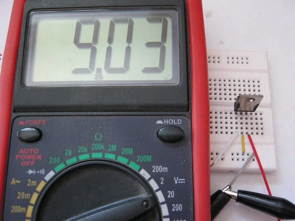
Now we take a zener diode for stabilization U \u003d 2.4 Volts and insert it according to this scheme, it is possible without capacitors, after all, we just do voltage measurements.

Whoa, 7.3 volts! 5 + 2.4 Volts. Works! Since my zener diodes are not high-precision (precision), the voltage of the zener diode may differ slightly from the passport voltage (voltage declared by the manufacturer). Well, I guess it's not a problem. 0.1 volts will not do the weather for us. As I said, in this way you can pick up any value out of the ordinary.
Option number 3
There is also another similar method, but diodes are used here. Maybe you know that the voltage drop at the direct junction of a silicon diode is 0.6-0.7 Volts, and a germanium diode is 0.3-0.4 Volts? It is this property of the diode that we will use ;-).
So, the scheme in the studio!

We assemble this design according to the scheme. The unstabilized input DC voltage also remained at 9 volts. Stabilizer 7805.

So what's the output?

Almost 5.7 Volts ;-), which was to be proved.
If two diodes are connected in series, then the voltage will drop across each of them, therefore, it will be summed up:

Each silicon diode drops 0.7 volts, which means 0.7 + 0.7 = 1.4 volts. Also with germanium. You can connect both three and four diodes, then you need to sum the voltages on each. In practice, more than three diodes are not used. Diodes can be installed even with low power, since in this case the current through them will still be small.
 School for an electrician: everything about electrical engineering and electronics Wiring and circuit diagrams
 How to make a small Damascus steel knife (without a mechanical hammer)
 Making Damascus Steel