The resistance for the LED is 12 volts. Good and bad LED circuits. Designation of the LED on the diagram
An LED is a diode that glows when current flows through it. In English, the LED is called light emitting diode, or LED.
The color of the LED glow depends on the additives added to the semiconductor. So, for example, impurities of aluminum, helium, indium, phosphorus cause a glow from red to yellow. Indium, gallium, nitrogen causes the LED to glow from blue to green. When a phosphor is added to a blue glow crystal, the LED will glow white. Currently, the industry produces glowing LEDs of all colors of the rainbow, but the color does not depend on the color of the LED case, but on the chemical additives in its crystal. LED of any color can have a transparent body.
The first LED was made in 1962 at the University of Illinois. In the early 1990s, bright LEDs appeared, and a little later super bright ones.
The advantage of LEDs over incandescent bulbs is undeniable, namely:
* Low power consumption - 10 times more efficient than light bulbs
* Long service life - up to 11 years of continuous operation
* High durability resource - not afraid of vibrations and shocks
* Large variety of colors
* Ability to work at low voltages
* Environmental and fire safety - the absence of toxic substances in the LEDs. LEDs do not heat up, which prevents fires.
LED marking

Rice. 1. The design of indicator 5 mm LEDs
An LED crystal is placed in the reflector. This reflector sets the initial scattering angle.
The light then passes through the epoxy resin housing. It reaches the lens - and then it begins to scatter on the sides at an angle depending on the design of the lens, in practice - from 5 to 160 degrees.
Emitting LEDs can be divided into two large groups: visible radiation LEDs and infrared (IR) LEDs. The former are used as indicators and illumination sources, the latter - in remote control devices, IR transceivers, and sensors.
Light emitting diodes are marked with a color code (Table 1). First you need to determine the type of LED by the design of its housing (Fig. 1), and then clarify it by color marking according to the table.

Rice. 2. Types of LED housings
LED colors
LEDs come in almost all colors: red, orange, yellow, yellow, green, blue and white. Blue and white LED is a little more expensive than other colors.
The color of LEDs is determined by the type of semiconductor material they are made of, not by the color of the plastic in their housing. LEDs of any color come in a colorless case, in which case the color can only be recognized by turning it on ...

Table 1. LED marking

Multicolor LEDs
A multi-color LED is arranged simply, as a rule, it is red and green combined into one housing with three legs. By changing the brightness or the number of pulses on each of the crystals, you can achieve different colors of glow.
LEDs are connected to a current source, anode to plus, cathode to minus. The minus (cathode) of the LED is usually marked with a small case cut or a shorter lead, but there are exceptions, so it is better to clarify this fact in the technical characteristics of a particular LED.

In the absence of these marks, the polarity can also be determined empirically by briefly connecting the LED to the supply voltage through the appropriate resistor. However, this is not the best way to determine polarity. In addition, in order to avoid thermal breakdown of the LED or a sharp reduction in its service life, it is impossible to determine the polarity by the “poke method” without a current-limiting resistor. For quick testing, a resistor with a nominal resistance of 1kΩ is suitable for most LEDs if the voltage is 12V or less.
You should immediately warn: you should not direct the LED beam directly into your eye (as well as into the eye of a friend) at close range, which can damage your eyesight.
Supply voltage
The two main characteristics of LEDs are voltage drop and current. Usually LEDs are rated at 20mA, but there are exceptions, for example, four-chip LEDs are usually rated at 80mA, since one LED package contains four semiconductor crystals, each of which consumes 20mA. For each LED, there are permissible values of the supply voltage Umax and Umaxrev (respectively for direct and reverse switching). When voltages above these values are applied, an electrical breakdown occurs, as a result of which the LED fails. There is also a minimum value of the supply voltage Umin, at which the LED glows. The range of supply voltages between Umin and Umax is called the "working" zone, since this is where the operation of the LED is ensured.
Supply voltage - the parameter for the LED is not applicable. LEDs do not have this characteristic, so you cannot connect LEDs to a power source directly. The main thing is that the voltage from which (through a resistor) the LED is powered should be higher than the direct voltage drop of the LED (the direct voltage drop is indicated in the characteristic instead of the supply voltage and for conventional indicator LEDs it ranges from 1.8 to 3.6 volts on average).
The voltage indicated on the packaging of the LEDs is not the supply voltage. This is the voltage drop across the LED. This value is needed to calculate the remaining voltage that “did not drop” on the LED, which takes part in the formula for calculating the resistance of the current limiting resistor, since it is it that needs to be regulated.
Changing the supply voltage by just one tenth of a volt at a conditional LED (from 1.9 to 2 volts) will cause a fifty percent increase in the current flowing through the LED (from 20 to 30 milliamps).
For each instance of an LED of the same rating, the voltage suitable for it may be different. By turning on several LEDs of the same rating in parallel, and connecting them to a voltage of, for example, 2 volts, we run the risk of quickly burning some copies and underlighting others due to the spread of characteristics. Therefore, when connecting the LED, it is necessary to monitor not the voltage, but the current.
The amount of current for the LED is the main parameter, and as a rule, it is 10 or 20 milliamps. It doesn't matter what the tension is. The main thing is that the current flowing in the LED circuit matches the nominal current for the LED. And the current is regulated by a resistor connected in series, the value of which is calculated by the formula:

R
Upit is the power supply voltage in volts.
Down- direct voltage drop across the LED in volts (indicated in the specifications and is usually in the region of 2 volts). When several LEDs are switched on in series, the magnitudes of the voltage drops add up.
I- the maximum forward current of the LED in amperes (indicated in the characteristics and is usually either 10 or 20 milliamps, i.e. 0.01 or 0.02 amperes). When several LEDs are connected in series, the forward current does not increase.
0,75
is the reliability factor for the LED.
You should also not forget about the power of the resistor. You can calculate the power using the formula:

P is the power of the resistor in watts.
Upit- effective (effective, rms) voltage of the power source in volts.
Down- direct voltage drop across the LED in volts (indicated in the specifications and is usually in the region of 2 volts). When several LEDs are switched on in series, the magnitudes of the voltage drops add up. .
R is the resistance of the resistor in ohms.
Calculation of the current-limiting resistor and its power for one LED
Typical characteristics of LEDs
Typical parameters of the white indicator LED: current 20 mA, voltage 3.2 V. Thus, its power is 0.06 W.

Also referred to low-power LEDs are surface-mounted - SMD. They illuminate the buttons in your cell phone, the screen of your monitor, if it is LED-backlit, they are used to make decorative LED strips on a self-adhesive basis and much more. There are two most common types: SMD 3528 and SMD 5050. The former contain the same crystal as indicator LEDs with leads, that is, its power is 0.06 W. But the second one - three such crystals, so it can no longer be called an LED - this is an LED assembly. It is customary to call SMD 5050 LEDs, but this is not entirely correct. These are assemblies. Their total power, respectively, is 0.2 watts.
The operating voltage of an LED depends on the semiconductor material from which it is made, respectively, there is a relationship between the color of the LED and its operating voltage.
LED voltage drop table depending on color

By the magnitude of the voltage drop when testing the LEDs with a multimeter, you can determine the approximate color of the LED glow according to the table.

Serial and parallel switching of LEDs
When connecting LEDs in series, the resistance of the limiting resistor is calculated in the same way as with one LED, just the voltage drops of all LEDs are added together according to the formula:

When connecting LEDs in series, it is important to know that all LEDs used in a garland must be of the same brand. This statement should not be taken as a rule, but as a law.
To find out what is the maximum number of LEDs that can be used in a garland, you should use the formula
![]()
* Nmax - the maximum allowable number of LEDs in a garland
* Upit - The voltage of the power source, such as a battery or accumulator. In volts.
* Upr - Direct voltage of the LED taken from its passport characteristics (usually in the range from 2 to 4 volts). In volts.
* As the temperature changes and the LED ages, Upr may increase. Coeff. 1.5 gives a margin for such a case.
In this count, "N" can be a fraction, such as 5.8. Naturally, you will not be able to use 5.8 LEDs, therefore, the fractional part of the number should be discarded, leaving only an integer, that is, 5.
The limiting resistor for series connection of LEDs is calculated in the same way as for a single connection. But in the formulas, one more variable “N” is added - the number of LEDs in the garland. It is very important that the number of LEDs in a garland be less than or equal to “Nmax” - the maximum allowable number of LEDs. In general, the following condition must be fulfilled: N = 
All other calculations are carried out in the same way as calculating a resistor when the LED is turned on alone.

If the power supply voltage is not enough even for two series-connected LEDs, then each LED must have its own limiting resistor.
Paralleling LEDs with a common resistor is a bad idea. As a rule, LEDs have a spread of parameters, require slightly different voltages each, which makes such a connection practically inoperative. One of the diodes will glow brighter and take on more current until it fails. Such a connection greatly accelerates the natural degradation of the LED crystal. If LEDs are connected in parallel, each LED must have its own limiting resistor.


Serial connection of LEDs is also preferable from the point of view of economical consumption of the power source: the entire series circuit consumes exactly as much current as one LED. And when they are connected in parallel, the current is as many times greater than how many parallel LEDs we have.
Calculating the limiting resistor for series-connected LEDs is as simple as for a single one. We simply sum up the voltage of all the LEDs, subtract the resulting sum from the power supply voltage (this will be the voltage drop across the resistor) and divide by the current of the LEDs (usually 15 - 20 mA).
And if we have a lot of LEDs, several dozen, and the power source does not allow us to connect them all in series (not enough voltage)? Then we determine, based on the voltage of the power source, how many LEDs we can connect in series. For example, for 12 volts, these are 5 two-volt LEDs. Why not 6? But after all, something must also fall on the limiting resistor. Here are the remaining 2 volts (12 - 5x2) and take it for calculation. For a current of 15 mA, the resistance will be 2/0.015 = 133 ohms. The closest standard is 150 ohms. But such chains of five LEDs and a resistor each, we can already connect as many as we like. This method is called a parallel-serial connection.
If there are LEDs of different brands, then we combine them in such a way that each branch has LEDs of only ONE type (or with the same operating current). In this case, it is not necessary to observe the same voltage, because we calculate our own resistance for each branch.

Next, consider a stabilized LED switching circuit. Let's touch on the manufacture of a current stabilizer. There is a KR142EN12 chip (foreign analogue of LM317), which allows you to build a very simple current stabilizer. To connect the LED (see figure), the resistance value is calculated R = 1.2 / I (1.2 - voltage drop not stabilizer) That is, at a current of 20 mA, R = 1.2 / 0.02 = 60 Ohm. Stabilizers are designed for a maximum voltage of 35 volts. It is better not to strain them like that and apply a maximum of 20 volts. With this inclusion, for example, a white LED of 3.3 volts, it is possible to supply voltage to the stabilizer from 4.5 to 20 volts, while the current on the LED will correspond to a constant value of 20 mA. At a voltage of 20V, we find that 5 white LEDs can be connected in series to such a stabilizer, without caring about the voltage on each of them, the current in the circuit will flow 20mA (the excess voltage will be extinguished on the stabilizer).
Important! In a device with a large number of LEDs, a large current flows. It is strictly forbidden to connect such a device to the switched on power supply. In this case, a spark occurs at the connection point, which leads to the appearance of a large current pulse in the circuit. This pulse disables the LEDs (especially the blue and white ones). If the LEDs operate in a dynamic mode (constantly on, off and blinking) and this mode is based on the use of a relay, then sparks on the relay contacts should be excluded.
Each chain should be assembled from LEDs of the same parameters and from the same manufacturer.
Also important! A change in ambient temperature affects the current flowing through the crystal. Therefore, it is desirable to manufacture the device so that the current flowing through the LED is not 20 mA, but 17-18 mA. The loss of brightness will be insignificant, but a long service life is guaranteed.
How to power an LED from a 220 V network.
It would seem that everything is simple: we put a resistor in series, and that's it. But you need to remember one important characteristic of the LED: the maximum allowable reverse voltage. Most LEDs have about 20 volts. And when you connect it to the network with reverse polarity (the current is alternating, half a period goes in one direction, and the other half goes in the opposite direction), the full amplitude voltage of the network will be applied to it - 315 volts! Where does such a figure come from? 220 V is the effective voltage, while the amplitude is in (root of 2) \u003d 1.41 times more.
Therefore, in order to save the LED, you need to put a diode in series with it, which will not let the reverse voltage pass to it.

Another option for connecting the LED to the mains 220v:

Or put two LEDs back-to-back.

The mains supply option with a quenching resistor is not the most optimal: significant power will be released on the resistor. Indeed, if we apply a 24 kΩ resistor (maximum current 13 mA), then the power dissipated on it will be about 3 watts. You can reduce it by half by turning on the diode in series (then heat will be released only during one half-cycle). The diode must be for a reverse voltage of at least 400 V. When you turn on two counter LEDs (there are even those with two crystals in one case, usually of different colors, one crystal is red, the other is green), you can put two two-watt resistors, each with a resistance twice less.
I will make a reservation that by using a high resistance resistor (for example, 200 kOhm), you can turn on the LED without a protective diode. The reverse breakdown current will be too low to cause crystal destruction. Of course, the brightness is very small, but for example, to illuminate the switch in the bedroom in the dark, it will be quite enough.
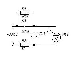
Due to the fact that the current in the network is alternating, it is possible to avoid unnecessary waste of electricity for heating the air with a limiting resistor. Its role can be played by a capacitor that passes alternating current without heating up. Why this is so is a separate question, we will consider it later. Now we need to know that in order for the capacitor to pass alternating current, both half-cycles of the network must necessarily pass through it. But an LED only conducts current in one direction. So, we put an ordinary diode (or a second LED) in opposite parallel to the LED, and it will skip the second half-cycle.

But now we have disconnected our circuit from the network. Some voltage remained on the capacitor (up to the full amplitude, if we remember, equal to 315 V). To avoid accidental electric shock, we will provide a high-value discharge resistor in parallel with the capacitor (so that during normal operation a small current flows through it, which does not cause it to heat up), which, when disconnected from the network, will discharge the capacitor in a fraction of a second. And to protect against pulsed charging current, we also put a low-resistance resistor. It will also play the role of a fuse, instantly burning out if the capacitor accidentally breaks down (nothing lasts forever, and this also happens).

The capacitor must be at least 400 volts, or special for alternating current circuits with a voltage of at least 250 volts.
And if we want to make an LED light bulb from several LEDs? We turn them all on in series, the oncoming diode is enough for one at all.

The diode must be designed for a current not less than the current through the LEDs, reverse voltage - not less than the sum of the voltage on the LEDs. Better yet, take an even number of LEDs and turn them on in anti-parallel.

In the figure, three LEDs are drawn in each chain, in fact there may be more than a dozen of them.
How to calculate a capacitor? From the amplitude voltage of the 315V network, we subtract the sum of the voltage drop across the LEDs (for example, for three white ones, this is about 12 volts). We get the voltage drop across the capacitor Up \u003d 303 V. The capacitance in microfarads will be equal to (4.45 * I) / Up, where I is the required current through the LEDs in milliamps. In our case, for 20 mA, the capacitance will be (4.45 * 20) / 303 = 89/303 ~= 0.3 uF. You can put two 0.15uF (150nF) capacitors in parallel.
The most common mistakes when connecting LEDs
1. Connecting the LED directly to a power source without a current limiter (resistor or special driver chip). Discussed above. The LED quickly fails due to a poorly controlled amount of current.

2. Connecting LEDs connected in parallel to a common resistor. Firstly, due to the possible scatter of parameters, the LEDs will light up with different brightness. Secondly, and more significantly, if one of the LEDs fails, the current of the second will double, and it may also burn out. In the case of using a single resistor, it is more expedient to connect the LEDs in series. Then, when calculating the resistor, we leave the current the same (for example, 10 mA), and add the forward voltage drop of the LEDs (for example, 1.8 V + 2.1 V = 3.9 V).

3. Turning on LEDs in series, designed for different currents. In this case, one of the LEDs will either wear out or glow dimly - depending on the current setting of the limiting resistor.

4. Installation of a resistor of insufficient resistance. As a result, the current flowing through the LED is too large. Since part of the energy is converted into heat due to defects in the crystal lattice, it becomes too much at high currents. The crystal overheats, as a result of which its service life is significantly reduced. With an even greater overestimation of the current, due to the heating of the p-n junction region, the internal quantum yield decreases, the brightness of the LED drops (this is especially noticeable for red LEDs), and the crystal begins to disintegrate catastrophically.

5. Connecting the LED to AC mains (eg 220V) without taking measures to limit reverse voltage. Most LEDs have a reverse voltage limit of about 2 volts, while the reverse half-cycle voltage when the LED is off creates a voltage drop across it equal to the supply voltage. There are many different schemes that exclude the destructive effect of reverse voltage. The simplest one is discussed above.

6. Installation of a resistor of insufficient power. As a result, the resistor gets very hot and begins to melt the insulation of the wires touching it. Then the paint burns on it, and in the end it collapses under the influence of high temperature. The resistor can painlessly dissipate no more than the power for which it is designed.

Flashing LEDs
The flashing LED (MSD) is a LED with a built-in integrated pulse generator with a flash frequency of 1.5-3 Hz.
Despite the compactness, the blinking LED includes a semiconductor chip generator and some additional elements. It is also worth noting that the flashing LED is quite versatile - the supply voltage of such an LED can range from 3 to 14 volts for high-voltage, and from 1.8 to 5 volts for low-voltage specimens.
Distinctive qualities of flashing set-diode:
- Small size
Compact light signaling device
Wide supply voltage range (up to 14 volts)
Different color of radiation.
In some variants of flashing LEDs, several (usually 3) multi-colored LEDs with different flash intervals can be built in.
The use of flashing LEDs is justified in compact devices, where there are high requirements for the dimensions of radio elements and power supply - flashing LEDs are very economical, because the MSD electronic circuit is made on MOS structures. A flashing LED can easily replace an entire functional unit.
The symbolic graphic designation of a blinking LED on schematic diagrams is no different from the designation of a conventional LED, except that the arrow lines are dotted and symbolize the blinking properties of the LED.
If you look through the transparent housing of the flashing LED, you will notice that it is structurally composed of two parts. On the basis of the cathode (negative terminal), a light-emitting diode crystal is placed.
The oscillator chip is located on the base of the anode terminal.
By means of three gold wire jumpers all parts of this combined device are connected.
It is easy to distinguish an MSD from a conventional LED by its appearance, looking at its case through the light. Inside the MSD are two substrates of approximately the same size. On the first of them is a crystalline light emitter cube made of a rare earth alloy.
A parabolic aluminum reflector (2) is used to increase the light flux, focus and shape the radiation pattern. In the MSD, it is slightly smaller in diameter than in a conventional LED, since the second part of the package is occupied by a substrate with an integrated circuit (3).
Both substrates are electrically connected to each other by two gold wire jumpers (4). The MSD body (5) is made of matte light-scattering plastic or transparent plastic.
The emitter in the MSD is not located on the axis of symmetry of the body, therefore, to ensure uniform illumination, a monolithic colored diffuse light guide is most often used. The transparent case is found only in MSDs of large diameters with a narrow radiation pattern.

The oscillator chip consists of a high-frequency master oscillator - it works constantly - its frequency, according to various estimates, fluctuates around 100 kHz. Together with the RF generator, a divider on logic elements works, which divides the high frequency to a value of 1.5-3 Hz. The use of a high-frequency generator in conjunction with a frequency divider is due to the fact that the implementation of a low-frequency generator requires the use of a capacitor with a large capacitance for the timing circuit.
To bring the high frequency to a value of 1-3 Hz, dividers on logical elements are used, which are easy to place on a small area of \u200b\u200bthe semiconductor crystal.
In addition to the master RF oscillator and the divider, an electronic key and a protective diode are made on the semiconductor substrate. For flashing LEDs, designed for a supply voltage of 3-12 volts, a limiting resistor is also built in. Low-voltage MSDs do not have a limiting resistor. A protective diode is required to prevent damage to the microcircuit when the power is reversed.
For reliable and long-term operation of high-voltage MSDs, it is desirable to limit the supply voltage to 9 volts. With an increase in voltage, the dissipated power of the MSD increases, and, consequently, the heating of the semiconductor crystal. Over time, excessive heat can cause the flashing LED to rapidly degrade.
You can safely check the serviceability of a flashing LED using a 4.5 volt battery and a 51 ohm resistor connected in series with the LED, with a power of at least 0.25 watts.
The health of the IR diode can be checked using a cell phone camera.
We turn on the camera in shooting mode, catch the diode on the device (for example, the remote control), press the buttons on the remote control, the working IR diode should flash in this case.

In conclusion, you should pay attention to issues such as soldering and mounting LEDs. These are also very important issues that affect their viability.
LEDs and microcircuits are afraid of static, improper connection and overheating, the soldering of these parts should be as fast as possible. You should use a low-power soldering iron with a tip temperature of no more than 260 degrees and soldering for no more than 3-5 seconds (manufacturer's recommendations). It will not be superfluous to use medical tweezers when soldering. The LED is taken with tweezers higher to the body, which provides additional heat removal from the crystal during soldering.
The legs of the LED should be bent with a small radius (so that they do not break). As a result of the intricate curves, the legs at the base of the case should remain in the factory position and should be parallel and not tense (otherwise it will get tired and the crystal will fall off the legs).
Although LEDs (lights) have been used in the world since the 60s, the question of how to connect them correctly is still relevant today.
To begin with, all LEDs operate exclusively on direct current. For them, the polarity of the connection, or the location of the plus and minus, is important. When connected incorrectly. the LED will not work.
How to determine the polarity of an LED
The polarity of an LED can be determined in three ways:

N.B. Although in practice the latter method is sometimes not confirmed.
Be that as it may, it should be noted that if the LED is not connected correctly for a short time (1-2 seconds), then nothing will burn out and nothing bad will happen. Since the diode itself works in one direction, but not in the opposite direction. It can burn out only due to increased voltage.
The nominal voltage for most LEDs is 2.2 - 3 volts. LED strips and modules that operate on 12 or more volts already contain resistors in the circuit.
How to connect an LED to 12 volts
It is forbidden to connect the LED directly to 12 volts, it will burn out in a split second. A terminating resistor (resistance) must be used. The dimension of the resistor is calculated by the formula:
R \u003d (Upit-Upad) / 0.75I,
where R is the resistance value of the resistor;
Upit and Upad - supply voltage and falling;
I - passing current.
0.75 - reliability coefficient for the LED (constant value)
For greater clarity, consider the example of connecting one LED to a 12 volt car battery.
In this case:
- Upit - 12 volts (voltage in a car battery)
- Upad - 2.2 volts (LED supply voltage)
- I - 10 mA or 0.01 A (current of one LED)
According to the above formula, we get R \u003d (12-2.2) / 0.75 * 0.01 \u003d 1306 Ohm or 1.306 kOhm
The closest standard resistor value is 1.3 kilo ohms
That's not all. It is required to calculate the required minimum power of the resistor.
But first, let's determine the actual current I (it may differ from the above)
Formula: I \u003d U / (Rres. + Rlight)
- Rlight - LED resistance:
Fall.nom. / Inom. = 2.2 / 0.01 = 220 ohms,
it follows that the current in the circuit
I \u003d 12 / (1300 + 220) \u003d 0.007 A
The actual LED voltage drop will be:
And finally, the power is:
P \u003d (Upit. - Upad.) ² / R \u003d (12 -1.54) ² / 1300 \u003d 0.0841 W).
You should take a little more power than the standard value. In this case, 0.125 watts is better.
So, in order to correctly connect one LED to 12 volts, (auto battery) you will need to insert a resistor into the circuit, with a resistance 1.3 kOhm and power 0.125 W.
The resistor can be connected to either leg of the LED.
Who at school had a solid deuce in mathematics - there is a simpler option. When buying LEDs from a radio store, ask the seller what kind of resistor you need to put in the circuit. Do not forget to indicate the voltage in the circuit.
How to connect an LED to 220v
The dimension of the resistance in this case is calculated in a similar way.
The original data is the same. LED with a consumption of 10 mA and a voltage of 2.2 volts.
Only the mains voltage is 220 volts AC.
R \u003d (Upit.-Upad.) / (I * 0.75)
R \u003d (220 - 2.2) / (0.01 * 0.75) \u003d 29040 Ohm or 29.040 kOhm
The nearest standard value resistor is 30 kΩ.
Power is calculated using the same formula.
First, we determine the actual current consumption:
I \u003d U / (Rres. + Rlight)
Rlight = Upad.nom. / Inom. = 2.2 / 0.01 = 220 ohms,
and from this it follows that the current in the circuit will be:
I \u003d 220 / (30000 + 220) \u003d 0.007 A
Thus, the actual voltage drop of the LED will be:
Upad.light \u003d R light * I \u003d 220 * 0.007 \u003d 1.54 V
And finally the power of the resistor:
P \u003d (Upit. - Upad.)² / R \u003d (220 -1.54)² / 30000 \u003d 1.59 W)
The resistance power should be at least 1.59 W, a little more is better. The nearest higher standard value is 2W.
So, to connect one LED to a voltage of 220 volts, we need to place a resistor with a nominal value of 30 kOhm and power 2 W.

BUT! Since in this case the current is alternating, the LED will burn only in one half-phase, that is, it will blink very quickly, at a rate of approximately 25 flashes per second. The human eye does not perceive this and it will seem that the light is usually on. But in fact, it will still miss reverse breakdowns, although it works only in one direction. To do this, you need to put a reverse diode in the circuit in order to balance the network and protect the LED from premature failure.
For the first time, LEDs began to be used in the early 60s. Since that time there have been changes. LEDs have many advantages, such as:
- Low consumption;
- Long service life;
- Strength;
- Wide range of light spectrum;
- Can operate on low voltage
- They are fireproof.
Because LEDs only need a constant current source to operate, they must be wired with the correct polarity. When the diodes are connected incorrectly, they will not function. In order for them to work correctly, it is important to know how to connect the LED.
Understanding the pros and cons
 The polarity is determined by several methods:
In older models that have long legs, everything is quite simple. The longer leg has a polarity of plus (anode), which is shorter - minus (cathode). Also on the head there is a cut that shows the location of the polarities.
If you look inside the diode, then the contact that looks like a flag is negative, thin will be a plus.
You can check with a multimeter. To do this, you must configure it for "ringing". Use the probes to touch the contacts. When it starts to glow, it means + on the red contact, and - on the black one.
Power exercise
The most important factor when choosing a power supply are the following values: current strength and voltage drop. Almost all of them are designed for a current strength of 20 milliamps, however, there are models that have 4 crystals at once, so it must be designed for a current strength four times greater. Also, the diode has its own allowable voltage Umax, with direct connection and Umaxrev, with reverse. When a higher voltage is applied, a breakdown occurs, after which the crystals no longer function. There is also a minimum voltage that is enough to power Umin, it is enough for the LED to work. These minimum and maximum limits are called the work zone. In the work area, the work of the LED should be carried out. If the calculation is wrong, the LED will simply burn out.
Each LED indicates a certain voltage, the marking is located on the package. It is important to know that this is the possible voltage drop and not the operating voltage. You need to know this in order to calculate the resistance of the resistor, whose task is to limit the current. For each individual LED of the same rating, the required voltage may vary. It is important to monitor the connection for current, not voltage.
Most of these light sources consume a nominal voltage of 2 - 3 volts. It is contraindicated to connect them directly to 12 volts, without using a limiting resistor. In many cases, to save money, they use a direct connection of the LED to the battery, without using a resistor, but such a light source will not last very long. For super bright LEDs, resistors are not used, since drivers are made for them that can limit the current. This is the most modern version of LEDs.
How to calculate a resistor
There is a formula for calculating the resistance of a resistor:
R \u003d (Upit-Upad) / 0.75I,
The resistance value is assumed to be R.
Supply voltage Upp.
Drop voltage Upad.
The flowing current is I.
The constant value of the diode reliability factor is 0.75.
For example, a connection to a 12 volt battery is considered. Then it will be:
- Upit - 12 volts, which implies battery voltage).
- Upad - 2.2 volts, which is the voltage to power the LED).
- I - 0.01 amperes, shows the current of the diode.
According to these figures, you can calculate using a formula that will show that the figure is 1.306. Since the resistors have a certain pitch, 1.3 kOhm will do.
The next task will be to calculate the required minimum for the power of the resistor. It is necessary to understand the exact figure of the passing current, because it may not correspond to the above. The calculation can be made using the following formula:
I \u003d U / (Rres. + Rlight)
The resistance that the diode has:
Rlight=Upad.nom. / Inom. = 2.2 / 0.01 = 220 ohms,
which says that the calculated actual current will be:
I \u003d 12 / (1300 + 220) \u003d 0.007 A.
To understand the actual voltage drop, you need to calculate:
Upad.light \u003d R light * I \u003d 220 * 0.007 \u003d 1.54 V
P \u003d (Upit. - Upad.)² / R \u003d (12 -1.54)² / 1300 \u003d 0.0841 W.
Power is better to take with a small margin. Now it will be just right 0.125 watts.
When connecting 1 LED to a 12 volt battery, a resistor is required in the network, which has a resistance of 1.3 kOhm and a power of 0.125 W.
Connection to 220 V network
For LEDs that require current from a 220 V network, it is important to know the most important point in the characteristics of the LED. This is especially true for questions on the topic of how to connect a powerful LED. The characteristic consists in the most permissible value of the reverse voltage. In many cases, it is 20 V. When mains power is supplied, with reverse polarity (alternating current), a full voltage amplitude of 315 V will come to it. This voltage was obtained because the amplitude voltage is almost one and a half times higher than the current one. For the LEDs to work, in addition to the resistor, you should install the LED through a series connection, which will not allow reverse voltage to break through it.
The next connection option from 220 V involves the arrangement of two diodes in anti-parallel.


A similar method, where the use of a resistor is provided, is not considered a correct connection. When using a 24 kΩ resistor, the dissipation energy will be approximately 3 watts. And when you connect the diode in series, you can reduce it by 2 times. For reverse voltage, the LED must have a voltage of at least 400 V. When 2 oncoming LEDs turn on, it is possible to insert two 2-watt resistors so that the resistance on each turns out to be 2 times less.
It is important to understand that using a resistor with a large resistance, for example, 200 kOhm, it is possible to turn it on without a protective diode. This is because the reverse current will be quite low to damage the diode. In this option, the brightness will be worse, but for some purposes, such as backlighting, it will be enough.
 Since the mains current is alternating, it is possible to include a capacitor in the circuit instead of a resistor. Compared to a limiting resistor, the capacitor does not heat up. In order for the capacitor to pass alternating current, both half-cycles of the network must pass through it. Since the LED can only conduct current to one of the sides, you need to put another LED or diode in anti-parallel. This will skip the second half cycle.
It is important to know that when the circuit is disconnected from the network, the capacitor contains a certain voltage, which can be equal to 315 V. To prevent accidental electric shock, a larger discharge resistor should be installed, placing it in parallel with the capacitor. The power reserve on the capacitor serves to ensure that during normal operation the current is negligible and does not cause heating. To provide protection against impulse charging currents, a low-resistance resistor is installed, which will be a fuse.
 Capacitor power should be from 400 V and above. There are options for circuits with alternating current voltage, suitable from 250 V and above. If multiple LEDs are to be driven, a serial connection should be used.

When LED lighting is installed, the diode must be calculated for a current that will be no less than the current passing through the LED. With reverse voltage, the calculation should be such that it is not less than the total term of the voltage on the LEDs. Using these recommendations, you can understand how to properly connect the LED.
Connection options from 12 V
From 12 V, you can connect in several ways. The 12V power supply can use a battery. In this example, 3 LEDs are connected.
There is an option to connect everything through your resistor, which  will perform the current limiting function.
Another option would be to turn on all the LEDs in parallel, installing 1 resistor, which is rated for triple current. However, the minus will be in the spread of parameters with LEDs of the same type. Accordingly, the LED, which has the weakest internal resistance, will be the first to pass increased currents and burn out. After that, the rest will also burn out, because the current for them will be very strong. As a result, it is necessary, as in the previous version, to install a resistor for each LED.
However, there is an alternative to this option. It is possible to make a series connection using only one resistor. So the current will pass through each LED evenly. It is important that the power supply does not have a voltage higher than the sum of the drops on each LED. Further, it is important to choose the right current limiting resistor and such an installation of LED backlighting can work for a long time.

Conclusion and video
To connect LEDs, you need to have a minimum level of theoretical knowledge, as well as be able to solder. If the minimum skills and knowledge of how to properly connect the LED are present, then this will not cause difficulties. If there is any doubt, then the question of how to connect the LED is better to entrust to specialists. The easiest option is to install LED lamps, which you can do yourself without any problems.
LEDs (12 volts) are often used for car tuning. They can also be installed to illuminate a small room. Devices of various shapes are produced, and they differ quite a lot in brightness. There are many manufacturers on the market. In order to connect the LED correctly, the type of power source must be taken into account. It is also important to evaluate the parameters of the model. To understand this issue, it is necessary to consider specific wiring diagrams for 12 V LEDs.
Connecting to a low-frequency power supply
At 12 volts, the LED is connected to a low-frequency power supply through a selective resistor. Modulators are used to adjust the luminous flux. Some experts recommend checking the nominal resistance in the circuit before connecting the LED. The specified parameter should not exceed 3.3 ohms. The conductivity of the modulator is also evaluated.

If we consider an open type device, then the specified parameter should be about 20 microns. Inexpensive switched modulators are also on the market. They have very high throughput. However, modulators of this type have several disadvantages. First of all, they have a very high power consumption. It is also important to consider that the color temperature of the device when using them reaches 700 microns. For 12V LEDs, this is quite a lot.
to high frequency power supply
A super-bright 12 volt LED can be connected to a high-frequency unit through a simple relay. In this case, the modulator is selected open type. Many experts advise not to use any amplifiers. First of all, they increase the luminous flux parameter. Thus, LEDs for lighting (12 volts) quickly overheat. On average, the current conductivity indicator should be 25 microns. Before connecting the LED to the network, the nominal resistance parameter is checked. Anyone can do this with a tester. On average, the nominal resistance when using an open modulator should be no more than 4 ohms. If we consider circuits with a large number of LEDs, then in this case you need to select a trigger. The specified element can be sold with or without a filter.

Serial connection
Most often, LEDs (12 volts) are connected in series. The result is a ribbon. Modulators are used to adjust the power of the luminous flux. Some specialists install expanders with regulators. In any case, the relay is selected for two contacts. It is also important to note that the nominal resistance parameter should not exceed 35 ohms. A pass type filter is installed in front of the expander. In order to avoid short circuits, an insulator is fixed at the end of the circuit. On average, the color temperature parameter should be no more than 500 K.
Parallel connection
LEDs are quite rare. In order for the lamps not to burn out, a contact modulator is used. If we consider the option with 12 V, then it is more expedient to use a pulse transceiver. On the market, it is sold with a protection system. On average, the current conductivity parameter does not exceed 30 microns. Amplifiers for connection are rarely used. In order to regulate the power of the luminous flux, it is allowed to use triggers.

If we consider two-digit modifications, then capacitors are used with one adapter. It is also important to note that the level of nominal resistance depends on the capacity of the resistor. If we consider the connection option with a three-digit trigger, then the capacitors are used without an adapter. In this case, the modulator may only be used with a thyristor. Voltage stabilization filters are rarely installed.
Circuits with capacitive capacitors
At 12 volts, the LED through a capacitive capacitor is only allowed to be connected in series. If we consider a circuit with a lamp strip, then the thyristor is used with one adapter. In this case, the filters are applied without winding. In order to avoid cases of short circuits, zener diodes are needed. They are quite compact. They should be installed after the filters. The capacitor in this case is fixed on the modulator. A controller is required to adjust the luminous flux. If you select a single-pole type device, then the nominal resistance parameter will be about 50 ohms. It is also important to note that the devices are dependent on the conductivity of the controller.

Using snubber capacitors
At 12 volts, the LED through a damping capacitor is allowed to be connected without an amplifier. The trigger in this case is used with one adapter. Many experts install the expander without an insulator. If we consider a circuit with one capacitor, then the modulator is used in an open type. It should be installed through an adapter. If we consider a circuit for two capacitors, then in this case the modulator is used as a closed type. It is also important to note that the resistor can only be installed with a regulator. To connect the controller, you will have to use a soldering iron. Before turning on the 12V LED, the overall nominal resistance level in the circuit is checked. The specified parameter should not exceed 35 ohms. If it is larger, then the resistor is selected with a higher power.
Application of absorbing filters
Small LEDs (12 volts) are quite easy to connect through an absorbing filter. In this case, the modulator can be installed with different bandwidth. The main advantage of absorbing filters lies in lowering the color temperature. As a result, they are able to work for a very long time. The luminous flux fluctuates on average around 4 lm. It is also important to note that thyristors are only used when connected in parallel. Controllers are needed to adjust the power of the luminous flux. They can be found on the market with or without lining. There are also other types that include tetrodes. In this case, they should not be considered.
LEDs with wave receivers
At 12 volts, the LED through the wave receiver is allowed to be connected only with an open modulator. In this case, resistors are used pulse type. Many experts recommend against the use of absorbing filters. The transceiver is installed with Sometimes the level of nominal resistance can be very high in the circuit. To solve the presented problem, you should use them. They are sold in different sizes on the market. The expander in the circuit is used with two adapters. If we consider a circuit with a trigger, then the LED should be installed through an amplifier. This will solve the problem with a sharp increase in color temperature.

Panasonic LED
LEDs (3mm) 12 volt "Panasonic" are often installed on cars. Wave transceivers are used to connect the model. They are very compact, it is also important to note that the devices do not require the installation of an additional amplifier. If we consider a circuit for two modulators, then the nominal resistance parameter should be about 40 ohms. It is also important to pay attention to the current conductivity indicator. For this purpose, you need to use the tester. Expanders are often used with a single adapter. In this case, a 12V LED is installed behind the resistor. On average, the nominal resistance should be about 45 ohms.

Philips LED
LEDs (12 volts) for Philips cars are connected through an open modulator. The color temperature of the model is 300 K. On average, the luminous flux of the device does not exceed 450 lm. If we consider a circuit with a conventional modulator, then LEDs (12 volts) for cars are used with a controller. In this case, it is important to install an insulator at the beginning of the circuit. Experts also recommend using an absorbing filter. To adjust the luminous flux of a 12 V LED, you cannot do without a high-quality controller. In this case, the resistor is selected single-pin type.
Connecting the Deluxe LED
The 12 V LED from the Deluxe company has a high color temperature parameter. In order for the device not to burn out during prolonged use, open modulators are installed. Recently, models began to be produced with pass-through resistors. They are designed to increase current conductivity. However, it is important to note that the rate of electricity consumption will increase significantly. The expander in front of the 12 V LED is installed with an insulator. Filters are most often used of the absorbing type. They should be installed at the beginning of the chain. Many experts check the nominal resistance level before turning on the LED. It should be no more than 55 ohms.
Energy-saving technologies and equipment are in demand and popular. One such device is the LED lamp. As a light source, it uses LEDs, which are combined into one circuit. This light bulb is used in lighting fixtures to design the illumination of buildings and structures, in spotlights that are mounted on suspended or suspended ceiling structures.
The design of LED lamps
LED lamps are designed for a voltage of 12 V and, accordingly, the design of the device differs from fluorescent counterparts or in which an incandescent filament is used. Structurally, it is made of the following main components:
- glass flask. It can be made of transparent or frosted glass and have a spherical or flat shape. The dome design increases the angle of dispersion of the light flux up to 270°. Models of light bulbs with a flat glass surface are used in spotlights to illuminate the interior or to divide the area into separate zones. Illumination angle 30 - 60°.
- LEDs. Light sources are connected in series in one connection scheme, which increases the light output of the device.
- Radiator. It is a metal plate made of aluminum alloy. It is designed to dissipate the heat emitted by the LEDs.
- Frame. It is made of high-strength plastic, which is a dielectric and performs protective functions against electric shock during installation or dismantling of the light source.
- Driver. Designed to stabilize voltage and convert current from AC to DC.
- plinth. It can be made for different types of cartridges: standard design E27 and E14 or G4, G13, GU10 and so on.
Depending on the amount of light emitted by one diode and the number, the brightness of the LED lamp is determined. The average value of illumination is calculated from the ratio of 1 Lm (Lumens - a unit of measurement of the brightness of the light flux) per 100 W.
Advantages and disadvantages of 12V lighting
To switch to lighting devices that are connected to a low-voltage power source, you should study their advantages and disadvantages. Among the advantages are the following:
- Safety. The use of LED lamps in 12V fixtures increases the level of protection and eliminates the possibility of electric shock.
- Fire safety. Low-voltage wiring cannot be a source of ignition and cause a fire. Therefore, the wires do not need additional protection, they are not placed in corrugated sleeves.
- Versatility. An electric current whose voltage does not exceed 12 V is considered conditionally safe, which cannot cause serious damage to a person. In this regard, these lamps can be used in rooms with normal conditions and increased danger. For example, in sauna lights, cellar, bathroom, kitchen, bedroom, etc.
- Saving. When using this light source to illuminate the room, it reduces energy consumption and, accordingly, the cost of money to pay bills.
- Environmental friendliness. The design does not use materials that, during the operation of the device, emit harmful substances to human or animal health.
- Reliability. The lamps are highly resistant to mechanical damage: scratches, chips, chipped, etc.
Despite all the advantages of the light source, it also has its drawbacks. The disadvantages of LED lamps designed for 12V include:
- An additional device is required - a power supply unit (PSU). The presence of a driver that stabilizes and lowers the mains voltage from 220 to 12 V complicates the wiring. It has its own efficiency, which reduces the efficiency of lighting and due to it an additional weak link appears in the circuit, which can fail.
- Glow brightness. The power of the luminous flux of a lamp connected to a low-voltage network is affected by a voltage drop. This is due to the high current consumption. Therefore, the length of the conductor from the transformer to the first and last light source must be the same, an error of 2 - 3% is allowed. Otherwise, the last lamp will shine dimmer than the first.
Varieties of LED lamps
Light sources are classified according to several criteria:
- Plinth type. Are issued traditional execution with standard sizes: E14, E27, E40. Baseless lamp models are also produced: G4, G5, G9, etc.
- glow temperature. There are three types of emitted light: soft - temperature from 2500 to 2700 °K, white - 3800 - 4500 °K and cold light flux temperature over 5000 °K
- LED type. Depending on the power and purpose of the lamp, LEDs have a different configuration, which is determined by the type of crystal. It can have legs for connection or be mounted directly on the board.

Power supply for LED lamps 12 V
Power supplies are selected depending on the purpose of LED lamps.

They are divided into the following types:
- Sealed. Are applied to installation of lamps in a bathroom, a sauna, street lighting.
- Leaky. Designed for installation indoors with a normal level of humidity.
- with active cooling. It is equipped with a fan, which contributes to an increase in power and a decrease in size.
- Passive cooling. A radiator is used to remove heat. The advantage is silent operation. The disadvantage is that the power is limited by the size of the device.
Also, power supplies are selected according to the main characteristics:
- Power. It is calculated by adding the entire connected load and plus a power reserve of 10 - 15% to prevent operation in overload mode.
- Output current. Depends on the number of connected lamps. If the load power and the “cosine phi” of the lamps are known, then the current can be calculated by the formula: total lamp power / 12 / cos φ. The parameter value also determines the cross-sectional area of the conductors connecting the PSU and lamps.
- Output voltage. For our case, this is 12V.
When connecting 12 V LED lamps to a 220 V electrical line, they must be powered by a driver or power supply.
Technological progress in the field of energy-saving technologies contributes to the continuous development and improvement of the technical and operational characteristics of LED lamps.
Related videos
 DIY digital frequency meter
 DIY Hearing Aid Hearing Aid Preamplifier Circuit
 Good and bad LED circuits