Movement of a body along an inclined plane. Methodology for teaching solving problems involving movement on an inclined plane Inclined plane and forces acting on it
This article talks about how to solve problems about moving along an inclined plane. A detailed solution to the problem of the motion of coupled bodies on an inclined plane from the Unified State Examination in Physics is considered.
Solving the problem of motion on an inclined plane
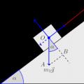
Before moving directly to solving the problem, as a tutor in mathematics and physics, I recommend carefully analyzing its condition. You need to start by depicting the forces that act on connected bodies:

Here and are the thread tension forces acting on the left and right bodies, respectively, are the support reaction force acting on the left body, and are the gravity forces acting on the left and right bodies, respectively. Everything is clear about the direction of these forces. The tension force is directed along the thread, the gravity force is vertically downward, and the support reaction force is perpendicular to the inclined plane.
But the direction of the friction force will have to be dealt with separately. Therefore, in the figure it is shown as a dotted line and signed with a question mark. It is intuitively clear that if the right load “outweighs” the left one, then the friction force will be directed opposite to the vector. On the contrary, if the left load “outweighs” the right one, then the friction force will be co-directed with the vector.
The right weight is pulled down by force N. Here we took the acceleration of gravity m/s 2. The left load is also pulled down by gravity, but not all of it, but only a “part” of it, since the load lies on an inclined plane. This “part” is equal to the projection of gravity onto the inclined plane, that is, the leg in the right triangle shown in the figure, that is, equal to H.
That is, the right load still “outweighs”. Consequently, the friction force is directed as shown in the figure (we drew it from the center of mass of the body, which is possible in the case when the body can be modeled by a material point):

The second important question that needs to be addressed is whether this coupled system will move at all? What if it turns out that the friction force between the left load and the inclined plane will be so great that it will not allow it to move?
This situation will be possible in the case when the maximum friction force, the modulus of which is determined by the formula (here - the coefficient of friction between the load and the inclined plane - the support reaction force acting on the load from the inclined plane), turns out to be greater than the force that is trying to bring the system into motion. That is, that very “outweighing” force that is equal to N.
The modulus of the support reaction force is equal to the length of the leg in the triangle according to Newton’s 3rd law (with the same magnitude of force the load presses on the inclined plane, with the same magnitude of force the inclined plane acts on the load). That is, the support reaction force is equal to N. Then the maximum value of the friction force is N, which is less than the value of the “overweighing force”.
Consequently, the system will move, and move with acceleration. Let us depict in the figure these accelerations and coordinate axes, which we will need later when solving the problem:

Now, after a thorough analysis of the problem conditions, we are ready to begin solving it.
Let's write down Newton's 2nd law for the left body:
And in the projection onto the axes of the coordinate system we get:

Here, projections are taken with a minus, the vectors of which are directed opposite the direction of the corresponding coordinate axis. Projections whose vectors are aligned with the corresponding coordinate axis are taken with a plus.
Once again we will explain in detail how to find projections and . To do this, consider the right triangle shown in the figure. In this triangle  And
And  . It is also known that in this right triangle . Then and.
The acceleration vector lies entirely on the axis, and therefore . As we already mentioned above, by definition, the modulus of the friction force is equal to the product of the friction coefficient and the modulus of the support reaction force. Hence, . Then the original system of equations takes the form:

Let us now write down Newton’s 2nd law for the right body:
In projection onto the axis we get.
In addition to the lever and block, simple mechanisms also include an inclined plane and its variations: a wedge and a screw.
INCLINED PLANE
An inclined plane is used to move heavy objects to a higher level without lifting them directly.
Such devices include ramps, escalators, conventional stairs and conveyors.
If you need to lift a load to a height, it is always easier to use a gentle lift than a steep one. Moreover, the steeper the slope, the easier it is to complete this work. When time and distance are not of great importance, but it is important to lift the load with the least effort, the inclined plane is indispensable.

These pictures can help explain how the simple INCLINED PLANE mechanism works.
Classical calculations of the action of an inclined plane and other simple mechanisms belong to the outstanding ancient mechanic Archimedes of Syracuse.
When building temples, the Egyptians transported, lifted and installed colossal obelisks and statues, weighing tens and hundreds of tons! All this could be done using, among other simple mechanisms, an inclined plane.
The main lifting device of the Egyptians was an inclined plane - a ramp. The frame of the ramp, that is, its sides and partitions. As the pyramid grew, the ramp was built on. Stones were dragged along these ramps on sleds. The ramp angle was very slight - 5 or 6 degrees.

Columns of the ancient Egyptian temple in Thebes.

Each of these huge columns was pulled by slaves along a ramp-an inclined plane. When the column crawled into the hole, sand was raked out through the hole, and then the brick wall was dismantled and the embankment was removed. Thus, for example, the inclined road to the Khafre pyramid, with a lift height of 46 meters, was about half a kilometer long.
A body on an inclined plane is held by a force whose magnitude is as many times less than the weight of this body as the length of the inclined plane is greater than its height."
This condition for the equilibrium of forces on an inclined plane was formulated by the Dutch scientist Simon Stevin (1548-1620).

A drawing on the title page of S. Stevin’s book, with which he confirms his formulation.

The inclined plane at the Krasnoyarsk hydroelectric power station was used very cleverly. Here, instead of locks, there is a ship-carrying chamber moving along an inclined overpass. To move it, a traction force of 4000 kN is required.

Why do mountain roads wind in gentle serpentines?
A wedge is a type of simple mechanism called an inclined plane. The wedge consists of two inclined planes, the bases of which are in contact. It is used to obtain a gain in strength, that is, with the help of a smaller force to counteract a larger force.
When chopping wood, to make the work easier, insert a metal wedge into the crack of the log and hit it with the butt of an ax.
The ideal gain in force given by a wedge is equal to the ratio of its length to its thickness at the blunt end. Due to the high friction, its efficiency is so low that the ideal gain does not matter much
Another type of inclined plane is a screw.
A screw is an inclined plane wound around an axis. The thread of a screw is an inclined plane that is repeatedly wrapped around a cylinder.
Due to the high friction, its efficiency is so low that the ideal gain does not matter much. Depending on the direction of rise of the inclined plane, the screw thread can be left-handed or right-handed.
Examples of simple devices with screw threads are a jack, a bolt with a nut, a micrometer, a vice.
Topics of the Unified State Examination codifier: simple mechanisms, mechanism efficiency.
Mechanism
- this is a device for converting force (increasing or decreasing it).
Simple mechanisms
- a lever and an inclined plane.
Lever arm.
Lever arm is a rigid body that can rotate around a fixed axis. In Fig.
1) shows a lever with an axis of rotation. Forces and are applied to the ends of the lever (points and ). The shoulders of these forces are equal to and respectively.
 |
| The equilibrium condition of the lever is given by the rule of moments: , whence |
Rice. 1. Lever
From this relationship it follows that the lever gives a gain in strength or distance (depending on the purpose for which it is used) as many times as the larger arm is longer than the smaller one.
For example, to lift a 700 N load with a force of 100 N, you need to take a lever with a 7:1 arm ratio and place the load on the short arm. We will gain 7 times in strength, but will lose the same amount of times in distance: the end of the long arm will describe a 7 times greater arc than the end of the short arm (that is, the load).
Examples of levers that provide a gain in strength are a shovel, scissors, and pliers. The rower's oar is the lever that gives the gain in distance. And ordinary lever scales are an equal-armed lever that does not provide any gain in either distance or strength (otherwise they can be used to weigh customers).
Fixed block. An important type of lever is block
- a wheel fixed in a cage with a groove through which a rope is passed. In most problems, a rope is considered to be a weightless, inextensible thread.
 |
In Fig.
Figure 2 shows a stationary block, i.e. a block with a stationary axis of rotation (passing perpendicular to the plane of the drawing through the point ).
At the right end of the thread, a weight is attached to a point. Let us recall that body weight is the force with which the body presses on the support or stretches the suspension. In this case, the weight is applied to the point where the load is attached to the thread.
Why then do we need a fixed block at all? It is useful because it allows you to change the direction of the effort. Typically a fixed block is used as part of more complex mechanisms.
Movable block.
In Fig. 3 shown moving block
 |
, the axis of which moves along with the load. We pull the thread with a force that is applied at a point and directed upward. The block rotates and at the same time also moves upward, lifting a load suspended on a thread.
At a given moment in time, the fixed point is the point, and it is around it that the block rotates (it would “roll” over the point). They also say that the instantaneous axis of rotation of the block passes through the point (this axis is directed perpendicular to the plane of the drawing).
The weight of the load is applied at the point where the load is attached to the thread. The leverage of force is equal to .
But the shoulder of the force with which we pull the thread turns out to be twice as large: it is equal to . Accordingly, the condition for equilibrium of the load is equality (which we see in Fig. 3: the vector is half as long as the vector).
Consequently, the movable block gives a double gain in strength. At the same time, however, we lose by the same two times in distance: in order to raise the load one meter, the point will have to be moved two meters (that is, pull out two meters of thread).
 |
The block in Fig.
3 there is one drawback: pulling the thread up (beyond the point) is not the best idea. Agree that it is much more convenient to pull the thread down! This is where the stationary block comes to our rescue.
In Fig. Figure 4 shows a lifting mechanism, which is a combination of a moving block and a fixed one. A load is suspended from the movable block, and the cable is additionally thrown over the fixed block, which makes it possible to pull the cable down to lift the load up. The external force on the cable is again symbolized by the vector .
Fundamentally, this device is no different from a moving block: with its help we also get a double gain in strength.
Inclined plane. As we know, it is easier to roll a heavy barrel along inclined walkways than to lift it vertically. The bridges are thus a mechanism that provides gains in strength. In mechanics, such a mechanism is called an inclined plane.
Inclined plane
 |
Let's select the axis as shown in the figure. Since the load moves without acceleration, the forces acting on it are balanced:
We project on the axis:
This is exactly the force that needs to be applied to move the load up an inclined plane.
To evenly lift the same load vertically, a force equal to . It can be seen that, since . An inclined plane actually gives a gain in strength, and the smaller the angle, the greater the gain.
Widely used types of inclined plane are wedge and screw.
The golden rule of mechanics.
A simple mechanism can give a gain in strength or distance, but cannot give a gain in work.
For example, a lever with a leverage ratio of 2:1 gives a double gain in strength. In order to lift a weight on the smaller shoulder, you need to apply force to the larger shoulder. But to raise the load to a height, the larger arm will have to be lowered by , and the work done will be equal to:
i.e. the same value as without using the lever.
In the case of an inclined plane, we gain in strength, since we apply a force to the load that is less than the force of gravity. However, in order to raise the load to a height above the initial position, we need to go along the inclined plane. At the same time we do work
i.e. the same as when lifting a load vertically.
These facts serve as manifestations of the so-called golden rule of mechanics.
The golden rule of mechanics. None of the simple mechanisms provide any gains in performance. The number of times we win in strength, the same number of times we lose in distance, and vice versa.
The golden rule of mechanics is nothing more than a simple version of the law of conservation of energy.
Efficiency of the mechanism.
In practice, we have to distinguish between useful work A useful, which must be accomplished using the mechanism under ideal conditions without any losses, and complete work A full,
which is performed for the same purposes in a real situation.
The total work is equal to the sum:
-useful work;
-work done against friction forces in various parts of the mechanism;
-work done to move the component elements of the mechanism.
So, when lifting a load with a lever, you have to additionally do work to overcome the frictional force in the axis of the lever and to move the lever itself, which has some weight.
Full work is always more useful. The ratio of useful work to total work is called the coefficient of performance (efficiency) of the mechanism:
=A useful/ A full
Efficiency is usually expressed as a percentage. The efficiency of real mechanisms is always less than 100%.
Let's calculate the efficiency of an inclined plane with an angle in the presence of friction. The coefficient of friction between the surface of the inclined plane and the load is equal to .
Let the mass load rise uniformly along the inclined plane under the action of force from point to point to a height (Fig. 6). In the direction opposite to the movement, the sliding friction force acts on the load.
 |
There is no acceleration, so the forces acting on the load are balanced:
We project on the X axis:
. (1)
We project on the Y axis:
. (2)
Besides,
, (3)
From (2) we have:
Then from (3):
Substituting this into (1), we get:
The total work is equal to the product of the force F and the path traveled by the body along the surface of the inclined plane:
A full=.
The useful work is obviously equal to:
A useful=.
For the required efficiency we obtain.
An inclined plane is a flat surface located at a particular angle to the horizontal. It allows you to lift a load with less force than if the load were lifted vertically. On an inclined plane, the load rises along this plane. At the same time, it covers a greater distance than if it rose vertically.
Note 1
Moreover, no matter how many times the gain in strength occurs, the distance that the load will cover will be greater.
Figure 1. Inclined plane
If the height to which the load must be raised is equal to $h$, and at the same time the force $F_h$ would be expended, and the length of the inclined plane is $l$, and at the same time the force $F_l$ is expended, then $l$ is so related to $h $, how $F_h$ relates to $F_l$: $l/h = F_h/F_l$... However, $F_h$ is the weight of the load ($P$). Therefore, it is usually written like this: $l/h = P/F$, where $F$ is the force lifting the load.
The magnitude of the force $F$ that must be applied to a load weighing $P$ in order for the body to be in equilibrium on an inclined plane is equal to $F_1 = P_h/l = Рsin(\mathbf \alpha )$, if the force $P$ is applied parallel to the inclined plane plane (Fig. 2, a), and $F_2$ = $Р_h/l = Рtg(\mathbf \alpha )$, if the force $Р$ is applied parallel to the base of the inclined plane (Fig. 2, b).

Figure 2. Movement of a load along an inclined plane
a) the force is parallel to the plane b) the force is parallel to the base
An inclined plane gives an advantage in strength; with its help, it is easier to lift a load to a height. The smaller the angle $\alpha $, the greater the gain in strength. If the angle $\alpha $ is less than the angle of friction, then the load will not move spontaneously, and force is needed to pull it down.
If we take into account the friction forces between the load and the inclined plane, then for $F_1$ and $F_2$ the following values are obtained: $F_1=Рsin($$(\mathbf \alpha )$$\pm$$(\mathbf \varphi )$) /cos$(\mathbf \varphi )$; $F_2=Рtg($$(\mathbf \alpha )$$\pm$$(\mathbf \varphi )$)
The plus sign refers to upward movement, the minus sign to lowering the load. Inclined plane efficiency $(\mathbf \eta )$1=sin$(\mathbf \alpha )$cos$(\mathbf \alpha )$/sin($(\mathbf \alpha )$+$(\mathbf \varphi )$), if the force $P$ is directed parallel to the plane, and $(\mathbf \eta )$2=tg$(\mathbf \alpha )$/tg($(\mathbf \alpha )$+$(\mathbf \varphi )$), if the force $P$ is directed parallel to the base of the inclined plane.
The inclined plane obeys the “golden rule of mechanics.” The smaller the angle between the surface and the inclined plane (i.e., the flatter it is, not steeply rising), the less force must be applied to lift the load, but the greater the distance will need to be overcome.
In the absence of friction forces, the gain in force is $K = P/F = 1/sin$$\alpha = l/h$. In real conditions, due to the action of friction, the efficiency of the inclined plane is less than 1, the gain in force is less than the ratio $l/h$.
Example 1
A load weighing 40 kg is lifted along an inclined plane to a height of 10 m while applying a force of 200 N (Fig. 3). What is the length of the inclined plane? Ignore friction.

$(\mathbf \eta )$ = 1
When a body moves along an inclined plane, the ratio of the applied force to the weight of the body is equal to the ratio of the length of the inclined plane to its height: $\frac(F)(P)=\frac(l)(h)=\frac(1)((sin (\ mathbf \alpha )\ ))$. Therefore, $l=\frac(Fh)(mg)=\ \frac(200\cdot 10)(40\cdot 9.8)=5.1\ m$.
Answer: The length of the inclined plane is 5.1 m
Example 2
Two bodies with masses $m_1$ = 10 g and $m_2$ = 15 g are connected by a thread thrown over a stationary block installed on an inclined plane (Fig. 4). The plane makes an angle $\alpha $ = 30$()^\circ$ with the horizon. Find the acceleration with which these bodies will move.

$(\mathbf \alpha )$ = 30 degrees
$g$ = 9.8 $m/s_2$
Let's direct the OX axis along the inclined plane, and the OY axis perpendicular to it, and project the vectors $\(\overrightarrow(P))_1\ and\(\overrightarrow(P))_2$ onto these axes. As can be seen from the figure, the resultant of the forces applied to each of the bodies is equal to the difference in the projections of the vectors $\(\overrightarrow(P))_1\ and\(\overrightarrow(P))_2$ onto the OX axis:
\[\left|\overrightarrow(R)\right|=\left|P_(2x)-P_(1x)\right|=\left|m_2g(sin \alpha \ )-m_1g(sin \alpha \ )\right |=g(sin \alpha \left|m_2-m_1\right|\ )\] \[\left|\overrightarrow(R)\right|=9.8\cdot (sin 30()^\circ \ )\cdot \ left|0.015-0.01\right|=0.0245\ H\]\
Answer: Acceleration of bodies $a_1=2.45\frac(m)(s^2);\ \ \ \ \ \ a_2=1.63\ m/s^2$
Similar to a lever, inclined planes reduce the force required to lift bodies. For example, it is quite difficult to lift a concrete block weighing 45 kilograms with your hands, but dragging it up an inclined plane is quite possible. The weight of a body placed on an inclined plane is decomposed into two components, one of which is parallel and the other perpendicular to its surface. To move a block up an inclined plane, a person must overcome only the parallel component, the magnitude of which increases with increasing angle of inclination of the plane.
Inclined planes are very diverse in design. For example, a screw consists of an inclined plane (thread) that spirals around its cylindrical part. When a screw is screwed into a part, its thread penetrates into the body of the part, forming a very strong connection due to the high friction between the part and the threads. The vise converts the lever action and rotary motion of the screw into a linear compressive force. The jack used to lift heavy loads works on the same principle.
Forces on an inclined plane

For a body located on an inclined plane, the force of gravity acts parallel and perpendicular to its surface. To move a body up an inclined plane, a force is required equal in magnitude to the component of gravity parallel to the surface of the plane.
Inclined planes and screws

The relationship between the screw and the inclined plane can be easily traced if you wrap a sheet of paper cut diagonally around the cylinder. The resulting spiral is identical in location to the screw thread.
Forces acting on the propeller

When a screw is turned, its thread creates a very large force applied to the material of the part into which it is screwed. This force pulls the propeller forward if it is turned clockwise and backward if it is turned counterclockwise.
Weight Lifting Screw

The rotating screws of jacks generate enormous force, allowing them to lift objects as heavy as cars or trucks. By turning the central screw with a lever, the two ends of the jack are pulled together, producing the necessary lift.
Inclined planes for splitting

The wedge consists of two inclined planes connected by their bases. When driving a wedge into a tree, the inclined planes develop lateral forces sufficient to split the strongest lumber.
Strength and work

Although an inclined plane may make the task easier, it does not reduce the amount of work required to complete it. Lifting a concrete block weighing 45 kg (W) 9 meters vertically upward (far picture on the right) requires 45 x 9 kilograms of work, which corresponds to the product of the weight of the block and the amount of movement. When the block is on a 44.5° inclined plane, the force (F) required to pull the block in is reduced to 70 percent of its weight. Although this makes it easier to move the block, now, in order to raise the block to a height of 9 meters, it must be dragged along a plane of 13 meters. In other words, the gain in strength is equal to the height of the lift (9 meters) divided by the length of movement along the inclined plane (13 meters).
 Methodology for teaching solving problems involving movement on an inclined plane Inclined plane and forces acting on it
 Actions of electric current: thermal, chemical, magnetic, light and mechanical. How is the magnetic action of electric current manifested?
 Deviations and tolerances of surface arrangement