Thermal power plants (CHP, IES): varieties, types, operating principles, fuel. Technological diagrams of power plants How gas-fired thermal power plants work
March 23rd, 2013
Once, when we were driving into the glorious city of Cheboksary, from the east, my wife noticed two huge towers standing along the highway. "And what is it?" - she asked. Since I absolutely did not want to show my wife my ignorance, I dug a little into my memory and came out victoriously: “These are cooling towers, don’t you know?” She was a little confused: “What are they for?” “Well, there’s something there to cool, it seems.” "And what?". Then I got embarrassed because I didn’t know how to get out of it any further.
This question may remain forever in the memory without an answer, but miracles happen. A few months after this incident, I see a post in my friend feed z_alexey about the recruitment of bloggers who want to visit the Cheboksary CHPP-2, the same one that we saw from the road. You have to suddenly change all your plans; missing such a chance would be unforgivable!
So what is CHP?
This is the heart of the power plant and where most of the action takes place. The gas entering the boiler burns, releasing a crazy amount of energy. “Clean water” is also supplied here. After heating, it turns into steam, more precisely into superheated steam, having an outlet temperature of 560 degrees and a pressure of 140 atmospheres. We will also call it “Clean Steam”, because it is formed from prepared water.
In addition to steam, we also have exhaust at the exit. At maximum power, all five boilers consume almost 60 cubic meters of natural gas per second! To remove combustion products you need a non-childish “smoke” pipe. And there is one like this too.
The pipe can be seen from almost any area of the city, given the height of 250 meters. I suspect that this is the tallest building in Cheboksary.
Nearby there is a slightly smaller pipe. Reserve again.
If the thermal power plant operates on coal, additional exhaust cleaning is necessary. But in our case this is not required, since natural gas is used as fuel.
The second section of the boiler-turbine shop contains installations that generate electricity.
There are four of them installed in the turbine hall of the Cheboksary CHPP-2, with a total capacity of 460 MW (megawatt). This is where superheated steam from the boiler room is supplied. It is directed under enormous pressure onto the turbine blades, causing the thirty-ton rotor to rotate at a speed of 3000 rpm.
The installation consists of two parts: the turbine itself, and a generator that generates electricity.
And this is what the turbine rotor looks like.
Sensors and pressure gauges are everywhere.
Both turbines and boilers can be stopped instantly in case of an emergency. For this, there are special valves that can shut off the supply of steam or fuel in a fraction of a second.
I wonder if there is such a thing as an industrial landscape, or an industrial portrait? There is beauty here.
There is a terrible noise in the room, and in order to hear your neighbor you have to strain your ears. Plus it's very hot. I want to take off my helmet and strip down to my T-shirt, but I can’t do that. For safety reasons, short-sleeved clothing is prohibited at the thermal power plant; there are too many hot pipes.
Most of the time the workshop is empty; people appear here once every two hours, during their rounds. And the operation of the equipment is controlled from the Main Control Panel (Group Control Panels for Boilers and Turbines).
This is what the duty officer's workplace looks like.
There are hundreds of buttons around.
And dozens of sensors.
Some are mechanical, some are electronic.
This is our excursion, and people are working.
In total, after the boiler-turbine shop, at the output we have electricity and steam that has partially cooled and lost some of its pressure. Electricity seems to be easier. The output voltage from different generators can be from 10 to 18 kV (kilovolts). With the help of block transformers, it increases to 110 kV, and then electricity can be transmitted over long distances using power lines (power lines).
It is not profitable to release the remaining “Clean Steam” to the side. Since it is formed from “Clean Water”, the production of which is a rather complex and costly process, it is more expedient to cool it and return it back to the boiler. So in a vicious circle. But with its help, and with the help of heat exchangers, you can heat water or produce secondary steam, which you can safely sell to third-party consumers.
In general, this is exactly how you and I get heat and electricity into our homes, having the usual comfort and coziness.
Oh yes. But why are cooling towers needed anyway?
It turns out everything is very simple. To cool the remaining “Clean Steam” before re-supplying it to the boiler, the same heat exchangers are used. It is cooled using technical water; at CHPP-2 it is taken directly from the Volga. It does not require any special preparation and can also be reused. After passing through the heat exchanger, the process water is heated and goes to the cooling towers. There it flows down in a thin film or falls down in the form of drops and is cooled by the counter flow of air created by fans. And in ejection cooling towers, water is sprayed using special nozzles. In any case, the main cooling occurs due to the evaporation of a small part of the water. The cooled water leaves the cooling towers through a special channel, after which, with the help of a pumping station, it is sent for reuse.
In a word, cooling towers are needed to cool the water, which cools the steam operating in the boiler-turbine system.
All work of the thermal power plant is controlled from the Main Control Panel.
There is always a duty officer here.
All events are logged.
Don't feed me bread, let me take a picture of the buttons and sensors...
That's almost all. Finally, there are a few photos of the station left.
This is an old pipe that is no longer working. Most likely it will be demolished soon.
There is a lot of agitation at the enterprise.
They are proud of their employees here.
And their achievements.
It seems that it was not in vain...
It remains to add that, as in the joke - “I don’t know who these bloggers are, but their tour guide is the director of the branch in Mari El and Chuvashia of TGC-5 OJSC, IES holding - Dobrov S.V.”
Together with the station director S.D. Stolyarov.
Without exaggeration, they are true professionals in their field.
And of course, many thanks to Irina Romanova, representing the company’s press service, for a perfectly organized tour.
The impeller blades of this steam turbine are clearly visible.
A thermal power plant (CHP) uses the energy released by burning fossil fuels - coal, oil and natural gas - to convert water into high-pressure steam. This steam, having a pressure of about 240 kilograms per square centimeter and a temperature of 524°C (1000°F), drives the turbine. The turbine spins a giant magnet inside a generator, which produces electricity.
Modern thermal power plants convert about 40 percent of the heat released during fuel combustion into electricity, the rest is discharged into the environment. In Europe, many thermal power plants use waste heat to heat nearby homes and businesses. Combined heat and power generation increases the energy output of the power plant by up to 80 percent.
Steam turbine plant with electric generator

A typical steam turbine contains two sets of blades. High-pressure steam coming directly from the boiler enters the flow path of the turbine and rotates the impellers with the first group of blades. The steam is then heated in the superheater and again enters the turbine flow path to rotate impellers with a second group of blades, which operate at a lower steam pressure.
Sectional view

A typical thermal power plant (CHP) generator is driven directly by a steam turbine, which rotates at 3,000 revolutions per minute. In generators of this type, the magnet, also called the rotor, rotates, but the windings (stator) are stationary. The cooling system prevents the generator from overheating.
Power generation using steam

At a thermal power plant, fuel burns in a boiler, producing a high-temperature flame. The water passes through the tubes through the flame, is heated and turns into high-pressure steam. The steam spins a turbine, producing mechanical energy, which a generator converts into electricity. After leaving the turbine, the steam enters the condenser, where it washes the tubes with cold running water, and as a result turns into a liquid again.
Oil, coal or gas boiler

Inside the boiler
The boiler is filled with intricately curved tubes through which heated water passes. The complex configuration of the tubes allows you to significantly increase the amount of heat transferred to the water and, as a result, produce much more steam.
Combined heat and power plant

The simplest schemes of combined heat and power plants with various turbines and various steam supply schemes
a - turbine with back pressure and steam extraction, heat release - according to an open circuit;
b - condensing turbine with steam extraction, heat release - according to open and closed circuits;
PC - steam boiler;
PP - steam superheater;
PT - steam turbine;
G - electric generator;
K - capacitor;
P - controlled production steam extraction for technological needs of industry;
T - adjustable district heating extraction;
TP - heat consumer;
OT - heating load;
KN and PN - condensate and feed pumps;
LDPE and HDPE - high and low pressure heaters;
D - deaerator;
PB - feed water tank;
SP - network heater;
SN - network pump.
Combined heat and power plant (CHP)- a thermal power plant that generates not only electrical energy, but also heat, supplied to consumers in the form of steam and hot water. The use of waste heat from engines rotating electric generators for practical purposes is a distinctive feature of thermal power plants and is called district heating. The combined production of two types of energy contributes to a more economical use of fuel compared to the separate generation of electricity at condensing power plants (in the USSR - state district power plants) and thermal energy at local boiler plants. Replacing local boiler houses, which use fuel irrationally and pollute the atmosphere of cities and towns, with a centralized heat supply system contributes not only to significant fuel savings, but also to increasing the cleanliness of the air basin and improving the sanitary condition of populated areas.
Description
The initial source of energy at thermal power plants is organic fuel (at steam turbine and gas turbine thermal power plants) or nuclear fuel (at nuclear thermal power plants). The predominant distribution are steam turbine thermal power plants using fossil fuels, which, along with condensing power plants, are the main type of thermal steam turbine power plants (TSPP). There are industrial type CHP plants - for supplying heat to industrial enterprises, and heating type - for heating residential and public buildings, as well as supplying them with hot water. Heat from industrial thermal power plants is transferred over a distance of up to several kilometers (mainly in the form of steam heat), from heating plants - over a distance of up to 20-30 km (in the form of hot water heat).
- Coal power plant in England
Cogeneration turbines
The main equipment of steam turbine thermal power plants is turbine units that convert the energy of the working substance (steam) into electrical energy, and boiler units that generate steam for turbines. The turbine unit includes a steam turbine and a synchronous generator. Steam turbines used in CHP plants are called combined heat and power turbines (CHTs). Among them, CTs are distinguished: with back pressure, usually equal to 0.7-1.5 Mn/m 2 (installed at thermal power plants that supply steam to industrial enterprises); with condensation and steam extraction under pressure of 0.7-1.5 Mn/m2 (for industrial consumers) and 0.05-0.25 Mn/m2 (for municipal consumers); with condensation and steam extraction (heating) under a pressure of 0.05-0.25 MN/m2.
The waste heat from backpressure CTs can be fully utilized. However, the electrical power developed by such turbines depends directly on the magnitude of the thermal load, and in the absence of the latter (as, for example, happens in the summer at heating thermal power plants), they do not generate electrical power. Therefore, CTs with back pressure are used only in the presence of a sufficiently uniform thermal load, ensured for the entire duration of the CHP operation (that is, mainly in industrial CHP plants).
In CTs with condensation and steam extraction, only extraction steam is used to supply heat to consumers, and the heat of the condensation steam flow is transferred to the cooling water in the condenser and is lost. To reduce heat losses, such CTs most of the time must operate according to the “thermal” schedule, that is, with minimal “ventilation” steam passage into the condenser. CTs with condensation and steam extraction have become predominantly widespread at thermal power plants as they are universal in possible operating modes. Their use makes it possible to regulate thermal and electrical loads almost independently; in a particular case, with reduced thermal loads or in their absence, a thermal power plant can operate according to an “electric” schedule, with the required, full or almost full electrical power.
Power of heating turbine units
The electrical power of heating turbine units (as opposed to condensing units) is preferably selected not according to a given power scale, but according to the amount of fresh steam they consume. Thus, turbine units R-100 with back pressure, PT-135 with industrial and heating extractions and T-175 with heating extraction have the same fresh steam consumption (about 750 t/h), but different electrical power (100, 135 and 175 MW, respectively) . The boiler units that produce steam for such turbines have the same productivity (about 800 t/h). This unification makes it possible to use turbine units of various types with the same thermal equipment of boilers and turbines at one thermal power plant. In the USSR, boiler units used to operate TPES for various purposes were also unified. Thus, boiler units with a steam capacity of 1000 t/h are used to supply steam to both 300 MW condensing turbines and the world’s largest 250 MW HPs.
The fresh steam pressure at thermal power plants is accepted in the USSR to be ~ 13-14 Mn/m 2 (mainly) and ~ 24-25 Mn/m 2 (at the largest heating power units - with a capacity of 250 MW). At thermal power plants with a steam pressure of 13-14 Mn/m 2, in contrast to state district power plants, there is no intermediate superheating of steam, since at such thermal power plants it does not provide such significant technical and economic advantages as at state regional power plants. Power units with a capacity of 250 MW at thermal power plants with a heating load are performed with intermediate superheating of steam.
The heat load at heating CHP plants is uneven throughout the year. In order to reduce costs for basic energy equipment, part of the heat (40-50%) during periods of increased load is supplied to consumers from peak water heating boilers. The share of heat released by the main power equipment at the highest load determines the value of the heating coefficient of the CHP plant (usually equal to 0.5-0.6). In the same way, it is possible to cover the peaks of thermal (steam) industrial load (about 10-20% of the maximum) with peak steam
October 24, 2012Electric energy has long entered our lives. Even the Greek philosopher Thales in the 7th century BC discovered that amber rubbed on wool begins to attract objects. But for a long time no one paid attention to this fact. It was only in 1600 that the term “Electricity” first appeared, and in 1650 Otto von Guericke created an electrostatic machine in the form of a sulfur ball mounted on a metal rod, which made it possible to observe not only the effect of attraction, but also the effect of repulsion. This was the first simple electrostatic machine.
Many years have passed since then, but even today, in a world filled with terabytes of information, when you can find out for yourself everything that interests you, for many it remains a mystery how electricity is produced, how it is delivered to our home, office, enterprise...
We will consider these processes in several parts.
Part I. Generation of electrical energy.
Where does electrical energy come from? This energy appears from other types of energy - thermal, mechanical, nuclear, chemical and many others. On an industrial scale, electrical energy is obtained at power plants. Let's consider only the most common types of power plants.
1) Thermal power plants. Today, all of them can be combined into one term - State District Power Plant (State District Power Plant). Of course, today this term has lost its original meaning, but it has not gone into eternity, but has remained with us.
Thermal power plants are divided into several subtypes:
A) A condensing power plant (CPP) is a thermal power plant that produces only electrical energy; this type of power plant owes its name to the peculiarities of its operating principle.
Operating principle: Air and fuel (gaseous, liquid or solid) are supplied to the boiler using pumps. The result is a fuel-air mixture that burns in the boiler furnace, releasing a huge amount of heat. In this case, the water passes through a pipe system, which is located inside the boiler. The released heat is transferred to this water, while its temperature rises and is brought to a boil. The steam that was produced in the boiler goes back into the boiler to overheat it above the boiling point of water (at a given pressure), then through steam lines it goes to the steam turbine, in which the steam does work. At the same time, it expands, its temperature and pressure decrease. Thus, the potential energy of the steam is transferred to the turbine, and therefore turns into kinetic energy. The turbine, in turn, drives the rotor of a three-phase alternating current generator, which is located on the same shaft as the turbine and produces energy.
Let's take a closer look at some elements of IES.
Steam turbine.

The flow of water vapor enters through guide vanes onto curved blades fixed around the circumference of the rotor, and, acting on them, causes the rotor to rotate. As you can see, there are gaps between the rows of shoulder blades. They are there because this rotor is removed from the housing. Rows of blades are also built into the body, but they are stationary and serve to create the desired angle of incidence of steam on the moving blades.
Condensing steam turbines are used to convert as much of the heat of steam as possible into mechanical work. They operate by discharging (exhausting) the spent steam into a condenser where a vacuum is maintained.
A turbine and a generator that are located on the same shaft are called a turbogenerator. Three-phase alternating current generator (synchronous machine).

It consists of:


Which increases the voltage to the standard value (35-110-220-330-500-750 kV). In this case, the current decreases significantly (for example, when the voltage increases by 2 times, the current decreases by 4 times), which makes it possible to transmit power over long distances. It should be noted that when we talk about voltage class, we mean linear (phase-to-phase) voltage.
The active power produced by the generator is regulated by changing the amount of energy carrier, and the current in the rotor winding changes. To increase the active power output, it is necessary to increase the steam supply to the turbine, and the current in the rotor winding will increase. We should not forget that the generator is synchronous, which means that its frequency is always equal to the frequency of the current in the power system, and changing the parameters of the energy carrier will not affect its rotation frequency.
In addition, the generator also produces reactive power. It can be used to regulate the output voltage within small limits (i.e. it is not the main means of regulating voltage in the power system). It works this way. When the rotor winding is overexcited, i.e. when the voltage on the rotor increases above the nominal value, “excess” reactive power is released into the power system, and when the rotor winding is underexcited, the reactive power is consumed by the generator.
Thus, in alternating current we are talking about apparent power (measured in volt-amperes - VA), which is equal to the square root of the sum of active (measured in watts - W) and reactive (measured in volt-amperes reactive - VAR) power.
The water in the reservoir serves to remove heat from the condenser. However, splash pools are often used for these purposes.

or cooling towers. Cooling towers can be tower type Fig.8

or fan Fig.9

Cooling towers are designed almost the same as the one, with the only difference being that water flows down the radiators, transfers heat to them, and they are cooled by the forced air. In this case, part of the water evaporates and is carried into the atmosphere.
The efficiency of such a power plant does not exceed 30%.
B) Gas turbine power plant.
In a gas turbine power plant, the turbogenerator is driven not by steam, but directly by gases produced during fuel combustion. In this case, only natural gas can be used, otherwise the turbine will quickly fail due to its contamination with combustion products. Efficiency at maximum load 25-33%
Much greater efficiency (up to 60%) can be obtained by combining steam and gas cycles. Such plants are called combined-cycle plants. Instead of a conventional boiler, they have a waste heat boiler installed, which does not have its own burners. It receives heat from the exhaust of a gas turbine. Currently, CCGTs are being actively introduced into our lives, but so far there are few of them in Russia.
IN) Thermal power plants (have become an integral part of large cities a long time ago). Fig.11

The thermal power plant is structurally designed as a condensing power plant (CPS). The peculiarity of a power plant of this type is that it can generate both thermal and electrical energy simultaneously. Depending on the type of steam turbine, there are various methods for extracting steam, which allow you to extract steam with different parameters from it. In this case, part of the steam or all of the steam (depending on the type of turbine) enters the network heater, transfers heat to it and condenses there. Cogeneration turbines allow you to regulate the amount of steam for thermal or industrial needs, which allows the CHP plant to operate in several load modes:
thermal - the production of electrical energy is completely dependent on the production of steam for industrial or district heating needs.
electrical - the electrical load is independent of the thermal load. In addition, CHP plants can operate in fully condensing mode. This may be required, for example, if there is a sharp shortage of active power in the summer. This mode is unprofitable for thermal power plants, because efficiency is significantly reduced.
The simultaneous production of electrical energy and heat (cogeneration) is a profitable process in which the efficiency of the station is significantly increased. For example, the calculated efficiency of CES is a maximum of 30%, and that of CHP is about 80%. Plus, cogeneration makes it possible to reduce idle thermal emissions, which has a positive effect on the ecology of the area in which the thermal power plant is located (compared to if there were a thermal power plant of similar capacity).
Let's take a closer look at the steam turbine.
Cogeneration steam turbines include turbines with:
Back pressure;
Adjustable steam extraction;
Selection and back pressure.
Turbines with back pressure operate by exhausting steam not into a condenser, as in IES, but into a network heater, that is, all the steam that goes through the turbine goes to heating needs. The design of such turbines has a significant drawback: the electrical load schedule is completely dependent on the thermal load schedule, that is, such devices cannot take part in the operational regulation of the frequency of the current in the power system.
In turbines with controlled steam extraction, it is extracted in the required quantity in intermediate stages, and the steps for steam extraction that are suitable in this case are selected. This type of turbine is independent of the thermal load and the control of the output active power can be adjusted within greater limits than in back-pressure CHP plants.
Extraction and backpressure turbines combine the functions of the first two types of turbines.
Cogeneration turbines of CHP plants are not always unable to change the heat load in a short period of time. To cover load peaks, and sometimes to increase electrical power by switching turbines to condensing mode, peak water heating boilers are installed at thermal power plants.
2) Nuclear power plants.
In Russia there are currently 3 types of reactor plants. The general principle of their operation is approximately similar to the operation of IES (in the old days, nuclear power plants were called state district power plants). The only fundamental difference is that thermal energy is obtained not in boilers using organic fuel, but in nuclear reactors.
Let's look at the two most common types of reactors in Russia.
1) RBMK reactor.

A distinctive feature of this reactor is that the steam for rotating the turbine is obtained directly in the reactor core.
RBMK core. Fig.13

consists of vertical graphite columns in which there are longitudinal holes, with pipes made of zirconium alloy and stainless steel inserted there. Graphite acts as a neutron moderator. All channels are divided into fuel and CPS (control and protection system) channels. They have different cooling circuits. A cassette (FA - fuel assembly) with rods (TVEL - fuel element) inside which are uranium pellets in a hermetically sealed shell is inserted into the fuel channels. It is clear that it is from them that thermal energy is obtained, which is transferred to a coolant continuously circulating from bottom to top under high pressure - ordinary water, but very well purified from impurities.

Water, passing through the fuel channels, partially evaporates, the steam-water mixture enters from all individual fuel channels into 2 separator drums, where steam is separated from water. The water again goes into the reactor using circulation pumps (4 in total per loop), and the steam goes through steam lines to 2 turbines. The steam then condenses in a condenser and turns into water, which goes back into the reactor.
The thermal power of the reactor is controlled only with the help of boron neutron absorber rods, which move in the control rod channels. The water cooling these channels comes from top to bottom.
As you may have noticed, I have never mentioned the reactor vessel yet. The fact is that, in fact, the RBMK does not have a hull. The active zone that I just told you about is placed in a concrete shaft, and on top it is closed with a lid weighing 2000 tons.

The above figure shows the upper biological protection of the reactor. But you shouldn’t expect that by lifting one of the blocks you will be able to see the yellow-green vent of the active zone, no. The cover itself is located significantly lower, and above it, in the space up to the upper biological protection, there remains a gap for communication channels and completely removed absorber rods.
Space is left between the graphite columns for thermal expansion of the graphite. A mixture of nitrogen and helium gases circulates in this space. Its composition is used to judge the tightness of the fuel channels. The RBMK core is designed to rupture no more than 5 channels; if more are depressurized, the reactor cover will tear off and the remaining channels will open. Such a development of events will cause a repetition of the Chernobyl tragedy (here I do not mean the man-made disaster itself, but its consequences).
Let's look at the advantages of the RBMK:
—Thanks to channel-by-channel regulation of thermal power, it is possible to change fuel assemblies without stopping the reactor. Every day, usually, several assemblies are changed.
—Low pressure in the CMPC (multiple forced circulation circuit), which contributes to a milder occurrence of accidents associated with its depressurization.
— Absence of a difficult-to-manufacture reactor vessel.
Let's look at the disadvantages of the RBMK:
—During operation, numerous errors were discovered in the geometry of the core, which cannot be completely eliminated at the existing power units of the 1st and 2nd generations (Leningrad, Kursk, Chernobyl, Smolensk). RBMK power units of the 3rd generation (there is only one - at the 3rd power unit of the Smolensk NPP) are free from these shortcomings.
—The reactor is single-circuit. That is, the turbines are rotated by steam produced directly in the reactor. This means that it contains radioactive components. If the turbine depressurizes (and this happened at the Chernobyl nuclear power plant in 1993), its repair will be greatly complicated, and perhaps impossible.
—The service life of the reactor is determined by the service life of the graphite (30-40 years). Then comes its degradation, manifested in its swelling. This process is already causing serious concern at the oldest RBMK power unit, Leningrad-1, built in 1973 (it is already 39 years old). The most likely way out of the situation is to plug the nth number of channels to reduce the thermal expansion of graphite.
—Graphite moderator is a flammable material.
—Due to the huge number of shut-off valves, the reactor is difficult to control.
— On the 1st and 2nd generations there is instability when operating at low powers.
In general, we can say that the RBMK is a good reactor for its time. At present, a decision has been made not to build power units with this type of reactor.
2) VVER reactor.
The RBMK is currently being replaced by VVER. It has significant advantages compared to the RBMK.
The core is completely contained in a very durable casing, which is manufactured at the plant and transported by rail and then by road to the power unit under construction in a completely finished form. The moderator is clean water under pressure. The reactor consists of 2 circuits: water from the first circuit under high pressure cools the fuel assemblies, transferring heat to the 2nd circuit using a steam generator (performs the function of a heat exchanger between 2 isolated circuits). In it, the secondary circuit water boils, turns into steam and goes to the turbine. In the primary circuit, the water does not boil, since it is under very high pressure. The exhaust steam is condensed in the condenser and goes back to the steam generator. The double-circuit circuit has significant advantages compared to the single-circuit one:
The steam going to the turbine is not radioactive.
The power of the reactor can be controlled not only by absorber rods, but also by a solution of boric acid, which makes the reactor more stable.
The primary circuit elements are located very close to each other, so they can be placed in a common containment shell. In case of ruptures in the primary circuit, radioactive elements will enter the containment and will not be released into the environment. In addition, the containment shell protects the reactor from external influences (for example, from the fall of a small aircraft or an explosion outside the perimeter of the station).
The reactor is not difficult to operate.
There are also disadvantages:
—Unlike the RBMK, fuel cannot be changed while the reactor is running, because it is located in a common housing, and not in separate channels, as in the RBMK. The time of fuel reloading usually coincides with the time of routine repairs, which reduces the impact of this factor on the installed capacity factor.
—The primary circuit is under high pressure, which could potentially cause a larger scale accident during depressurization than the RBMK.
—The reactor vessel is very difficult to transport from the manufacturing plant to the nuclear power plant construction site.
Well, we have looked at the work of thermal power plants, now let’s look at the work

The operating principle of a hydroelectric power station is quite simple. A chain of hydraulic structures provides the necessary pressure of water flowing to the blades of a hydraulic turbine, which drives generators that produce electricity.
The required water pressure is formed through the construction of a dam, and as a result of the concentration of the river in a certain place, or by diversion - the natural flow of water. In some cases, both a dam and a diversion are used together to obtain the required water pressure. Hydroelectric power plants have very high flexibility of generated power, as well as low cost of generated electricity. This feature of hydroelectric power plants led to the creation of another type of power plant - pumped storage power plant. Such stations are capable of accumulating generated electricity and using it at times of peak load. The operating principle of such power plants is as follows: at certain periods (usually at night), pumped storage power plant hydroelectric units operate like pumps, consuming electrical energy from the power system, and pumping water into specially equipped upper pools. When demand arises (during peak loads), water from them enters the pressure pipeline and drives the turbines. PSPPs perform an extremely important function in the energy system (frequency regulation), but they are not widely used in our country, because they end up consuming more power than they produce. That is, a station of this type is unprofitable for the owner. For example, at the Zagorskaya PSPP the capacity of hydrogenerators in generator mode is 1200 MW, and in pumping mode – 1320 MW. However, this type of station is best suited for quickly increasing or decreasing the generated power, so it is advantageous to build them near, for example, nuclear power plants, since the latter operate in basic mode.
We have looked at exactly how electrical energy is produced. It’s time to ask yourself a serious question: “What type of stations best meets all modern requirements for reliability, environmental friendliness, and, in addition, will also have a low energy cost?” Everyone will answer this question differently. Let me give you my list of the “best of the best”.
1) CHP powered by natural gas. The efficiency of such stations is very high, the cost of fuel is also high, but natural gas is one of the “cleanest” types of fuel, and this is very important for the ecology of the city, within the boundaries of which thermal power plants are usually located.
2) HPP and PSPP. The advantages over thermal stations are obvious, since this type of station does not pollute the atmosphere and produces the “cheapest” energy, which, in addition, is a renewable resource.
3) CCGT power plant using natural gas. The highest efficiency among thermal stations, as well as the small amount of fuel consumed, will partially solve the problem of thermal pollution of the biosphere and limited reserves of fossil fuels.
4) Nuclear power plant. In normal operation, a nuclear power plant emits 3-5 times less radioactive substances into the environment than a thermal station of the same power, so the partial replacement of thermal power plants with nuclear ones is completely justified.
5) GRES. Currently, such stations use natural gas as fuel. This is absolutely meaningless, since with the same success in the furnaces of state district power plants it is possible to utilize associated petroleum gas (APG) or burn coal, the reserves of which are huge compared to the reserves of natural gas.
This concludes the first part of the article.
Material prepared by:
student of group ES-11b South-West State University Agibalov Sergey.
What is it and what are the operating principles of thermal power plants? The general definition of such objects sounds approximately as follows - these are power plants that process natural energy into electrical energy. Fuel of natural origin is also used for these purposes.
The operating principle of thermal power plants. Short description
Today, it is precisely at such facilities that combustion is most widespread that releases thermal energy. The task of thermal power plants is to use this energy to produce electrical energy.
The operating principle of thermal power plants is not only the generation but also the production of thermal energy, which is also supplied to consumers in the form of hot water, for example. In addition, these energy facilities generate about 76% of all electricity. This widespread use is due to the fact that the availability of fossil fuels for the operation of the station is quite high. The second reason was that transporting fuel from the place of its extraction to the station itself is a fairly simple and streamlined operation. The operating principle of thermal power plants is designed in such a way that it is possible to use the waste heat of the working fluid for its secondary supply to the consumer.
Separation of stations by type
It is worth noting that thermal stations can be divided into types depending on what kind of heat they produce. If the principle of operation of a thermal power plant is only to produce electrical energy (that is, it does not supply thermal energy to the consumer), then it is called condensing power plant (CES).

Facilities intended for the production of electrical energy, for the supply of steam, as well as the supply of hot water to the consumer, have steam turbines instead of condensing turbines. Also in such elements of the station there is an intermediate steam extraction or a backpressure device. The main advantage and operating principle of this type of thermal power plant (CHP) is that waste steam is also used as a heat source and supplied to consumers. This reduces heat loss and the amount of cooling water.
Basic operating principles of thermal power plants
Before moving on to considering the principle of operation itself, it is necessary to understand what kind of station we are talking about. The standard design of such facilities includes a system such as intermediate superheating of steam. It is necessary because the thermal efficiency of a circuit with intermediate superheating will be higher than in a system without it. In simple words, the operating principle of a thermal power plant with such a scheme will be much more efficient with the same initial and final specified parameters than without it. From all this we can conclude that the basis of the station’s operation is organic fuel and heated air.

Scheme of work
The operating principle of the thermal power plant is constructed as follows. The fuel material, as well as the oxidizer, the role of which is most often played by heated air, is fed in a continuous flow into the boiler furnace. Substances such as coal, oil, fuel oil, gas, shale, and peat can act as fuel. If we talk about the most common fuel on the territory of the Russian Federation, it is coal dust. Further, the operating principle of thermal power plants is constructed in such a way that the heat generated by burning fuel heats the water in the steam boiler. As a result of heating, the liquid is converted into saturated steam, which enters the steam turbine through the steam outlet. The main purpose of this device at the station is to convert the energy of the incoming steam into mechanical energy.

All elements of the turbine that can move are closely connected to the shaft, as a result of which they rotate as a single mechanism. To make the shaft rotate, a steam turbine transfers the kinetic energy of steam to the rotor.
Mechanical part of the station
The design and principle of operation of a thermal power plant in its mechanical part is associated with the operation of the rotor. The steam that comes from the turbine has very high pressure and temperature. Because of this, high internal energy of steam is created, which flows from the boiler into the turbine nozzles. Jets of steam, passing through the nozzle in a continuous flow, at high speed, which is often even higher than sound speed, act on the turbine blades. These elements are rigidly fixed to the disk, which, in turn, is closely connected to the shaft. At this point in time, the mechanical energy of the steam is converted into the mechanical energy of the rotor turbines. If we talk more precisely about the principle of operation of thermal power plants, then the mechanical impact affects the rotor of the turbogenerator. This is due to the fact that the shaft of a conventional rotor and generator are tightly coupled to each other. And then there is a fairly well-known, simple and understandable process of converting mechanical energy into electrical energy in a device such as a generator.

Steam movement after the rotor
After the water vapor passes the turbine, its pressure and temperature drop significantly, and it enters the next part of the station - the condenser. Inside this element, the vapor is converted back into liquid. To perform this task, there is cooling water inside the condenser, which is supplied there through pipes running inside the walls of the device. After the steam is converted back into water, it is pumped out by a condensate pump and enters the next compartment - the deaerator. It is also important to note that the pumped water passes through regenerative heaters.
The main task of the deaerator is to remove gases from the incoming water. Simultaneously with the cleaning operation, the liquid is heated in the same way as in regenerative heaters. For this purpose, the heat of the steam is used, which is taken from what goes into the turbine. The main purpose of the deaeration operation is to reduce the oxygen and carbon dioxide content in the liquid to acceptable values. This helps reduce the rate of corrosion on the paths through which water and steam are supplied.

Coal stations
There is a high dependence of the operating principle of thermal power plants on the type of fuel used. From a technological point of view, the most difficult substance to implement is coal. Despite this, raw materials are the main source of power at such facilities, the number of which is approximately 30% of the total share of stations. In addition, it is planned to increase the number of such objects. It is also worth noting that the number of functional compartments required for the operation of the station is much greater than that of other types.
How do thermal power plants run on coal fuel?
In order for the station to operate continuously, coal is constantly brought in along the railway tracks, which is unloaded using special unloading devices. Then there are elements such as through which unloaded coal is supplied to the warehouse. Next, the fuel enters the crushing plant. If necessary, it is possible to bypass the process of delivering coal to the warehouse and transfer it directly to the crushers from unloading devices. After passing this stage, the crushed raw materials enter the raw coal bunker. The next step is to supply the material through feeders to the pulverized coal mills. Next, the coal dust, using a pneumatic transportation method, is fed into the coal dust bunker. Along this path, the substance bypasses elements such as a separator and a cyclone, and from the hopper it already flows through the feeders directly to the burners. The air passing through the cyclone is sucked in by the mill fan and then fed into the combustion chamber of the boiler.

Further, the gas movement looks approximately as follows. The volatile substance formed in the chamber of the combustion boiler passes sequentially through such devices as the gas ducts of the boiler plant, then, if a steam reheat system is used, the gas is supplied to the primary and secondary superheater. In this compartment, as well as in the water economizer, the gas gives up its heat to heat the working fluid. Next, an element called an air superheater is installed. Here the thermal energy of the gas is used to heat the incoming air. After passing through all these elements, the volatile substance passes into the ash collector, where it is cleaned of ash. After this, smoke pumps draw the gas out and release it into the atmosphere using a gas pipe.
Thermal power plants and nuclear power plants
Quite often the question arises about what is common between thermal power plants and whether there are similarities in the operating principles of thermal power plants and nuclear power plants.
If we talk about their similarities, there are several of them. Firstly, both of them are built in such a way that for their work they use a natural resource that is fossil and excreted. In addition, it can be noted that both objects are aimed at generating not only electrical energy, but also thermal energy. The similarities in operating principles also lie in the fact that thermal power plants and nuclear power plants have turbines and steam generators involved in the operation process. Further there are only some differences. These include the fact that, for example, the cost of construction and electricity obtained from thermal power plants is much lower than from nuclear power plants. But, on the other hand, nuclear power plants do not pollute the atmosphere as long as the waste is disposed of correctly and no accidents occur. While thermal power plants, due to their operating principle, constantly emit harmful substances into the atmosphere.
Here lies the main difference in the operation of nuclear power plants and thermal power plants. If in thermal facilities the thermal energy from fuel combustion is most often transferred to water or converted into steam, then at nuclear power plants the energy is taken from the fission of uranium atoms. The resulting energy is used to heat a variety of substances and water is used here quite rarely. In addition, all substances are contained in closed, sealed circuits.
District heating
At some thermal power plants, their design may include a system that handles heating of the power plant itself, as well as the adjacent village, if there is one. To the network heaters of this installation, steam is taken from the turbine, and there is also a special line for condensate removal. Water is supplied and discharged through a special pipeline system. The electrical energy that will be generated in this way is removed from the electrical generator and transmitted to the consumer, passing through step-up transformers.
Basic equipment
If we talk about the main elements operated at thermal power plants, these are boiler houses, as well as turbine units paired with an electric generator and a capacitor. The main difference between the main equipment and the additional equipment is that it has standard parameters in terms of its power, productivity, steam parameters, as well as voltage and current, etc. It can also be noted that the type and number of main elements are selected depending on how much power needs to be obtained from one thermal power plant, as well as its operating mode. An animation of the operating principle of thermal power plants can help to understand this issue in more detail.
 The best views from Moscow windows (photo)
 How it's made, how it works, how it works
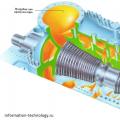 Technological diagrams of power plants How gas-fired thermal power plants work